Constructing a barn hay dryer
Learn about installing a hay drying system on the farm. This technical information is for Ontario producers.
ISSN 1198-712X, Published May 2021
Introduction
Barn hay drying systems are commonly installed as a basic component in the production of quality forage. A properly managed hay drying system reduces field curing time, lessens the risk of losses due to rain, minimizes leaf loss and eliminates the danger of fire due to spontaneous combustion.
A barn hay dryer makes use of a suitable fan and air duct distribution system to force outside air through partially dried hay, placed in storage. This movement of air through the hay removes heat and excess moisture and eventually completes the drying process, which started in the field.
Consider the following factors when investigating the installation of a hay drying system for the farm:
- mow floor
- airflow rates
- drying fan
- air distribution systems
- system design
- harvesting and filling
- operation of dryer
- cost
Mow floor
Hay to be dried on the mow floor will weigh 10%–30% more than field-dried hay. Check all floor supports and strengthen or replace them if necessary.
The mow floor must be airtight so that air is forced through the hay and not through the floor. The floor can be sealed with a 0.15-mm (6-mil) polyethylene plastic or covered with 8-mm (5⁄16-in.) plywood.
Airflow rates
Design hay dryers to complete the curing of tough or damp hay. Do not expect them to dry wet hay. The amount of airflow required depends on the initial moisture content of the hay and the grass‑legume mixture of the forage. Use the airflow rates in Table 1 as a guideline.
| Moisture content % | Airflow rates (cfm/ton) | Airflow rates (L/s/tonne) |
|---|---|---|
| <25 | 150 | 80 |
| 25–30 | 300 | 160 |
| 30–35 | 500 | 260 |
The most desirable average moisture content of hay for barn drying is 25% or less. An average moisture content exceeding 30% is very risky for artificial drying.
For calculation purposes, 0.9 tonne (1 ton) of dry baled hay occupies approximately 7.0 m3 (250 ft3) of space — approximately 50 standard bales weighing 18 kg (40 lb) each.
Drying fan
Example system: fan selection
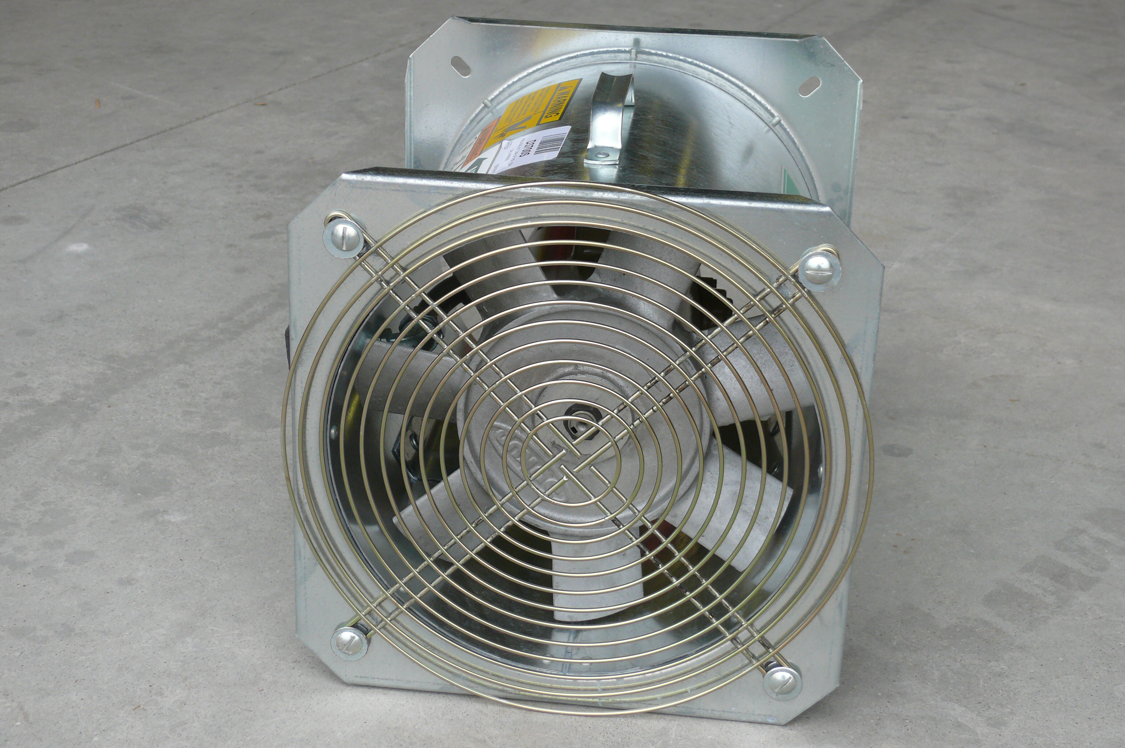
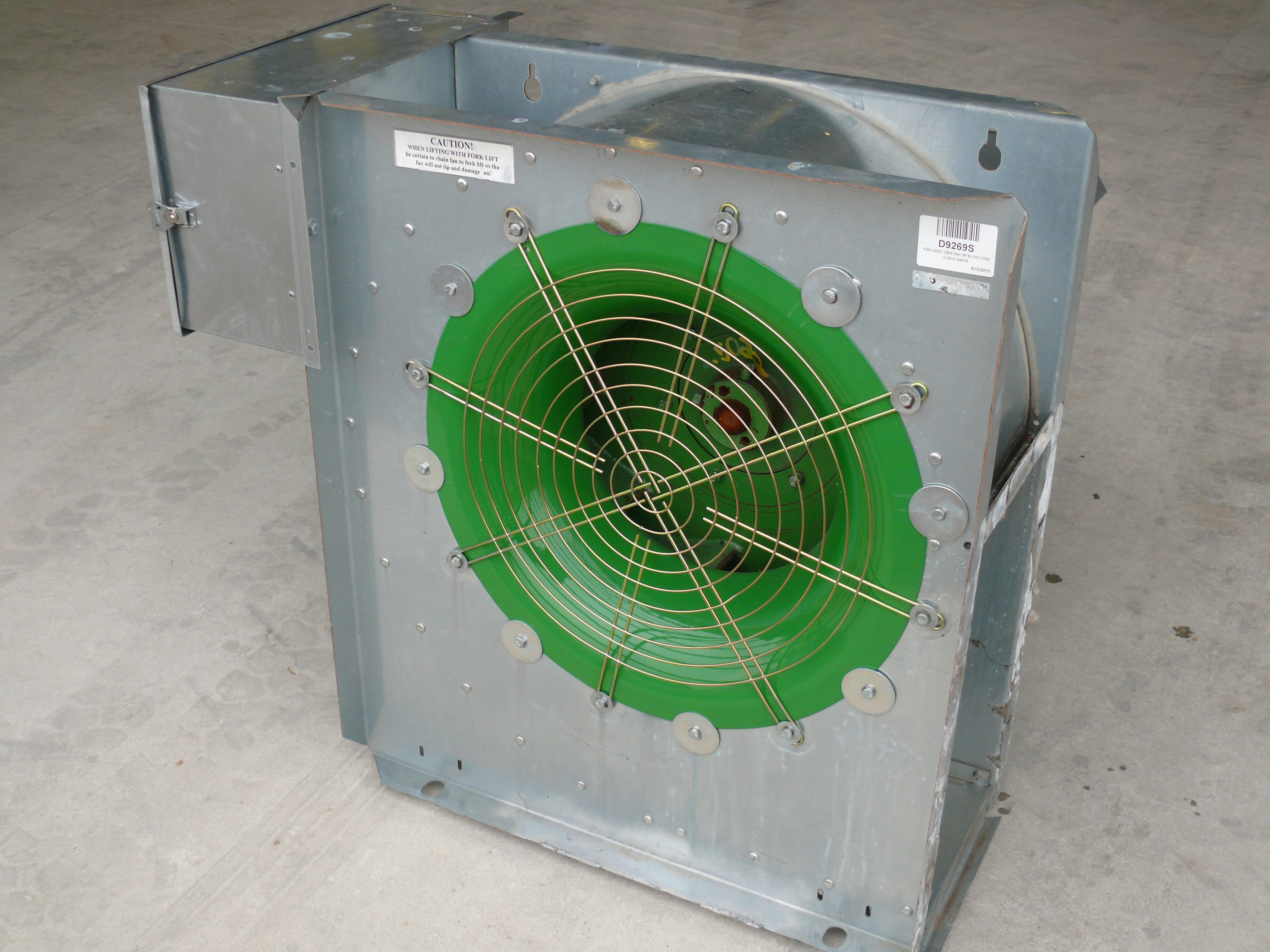
Select the fan to deliver the desired amount of air at a static pressure of 0.25 kPa (1 in.). There are two types of fans used: the axial flow (propeller) fan (Figure 1) or the centrifugal fan (Figure 2). A centrifugal fan operates much more quietly than an axial fan but is more expensive.
Generally, 3.7-kW (5-hp) or 5.6-kW (7.5-hp) axial or centrifugal fans are readily available. If necessary, install more than one fan in the hay storage to meet the airflow requirements.
If centrifugal fans are used to dry the hay, keep a constant check on the drive belt tension. Any loss in revolutions per minute due to excessive belt slippage will reduce the fan output considerably.
As part of the planning process, consider the electrical requirements for the fan motor, as they can be substantial. Locate the fan where it is easy to reach for maintenance and repair and protected from the weather. When selecting the fan location, remember that it will be running continuously for a period of time and making considerable noise.
Example
Calculate the required fan capacity to dry a mow of hay with dimensions 9.1 m (30 ft) × 21.3 m (70 ft) × 3.65 m (12 ft) deep, when the hay has an initial moisture content of 25%.
Solution
Volume of storage
= length × width × height
= 9.1 m (30 ft) × 21.3 m (70 ft) × 3.65 m (12 ft)
= 707 m3 (25,200 ft3)
0.9 tonne (1 ton) of dry baled hay occupies 7.0 m3 (250 ft3); thus the mow hay volume is 707 m3 (25,200 ft3). The mow hay volume divided by 7.0 m3 (250 ft3) equals approximately 90 tonnes (100 tons).
For 25% hay moisture content, the airflow rate is 80 L/s/tonne (150 cfm/ton) (Table 1). Select a fan that will deliver 90 tonne (100 ton) × 80 L/s/tonne (150 cfm/ton) = 7,200 L/s (15,000 cfm) of air at 0.25 kPa (1 in.) static pressure.
Check with your supplier for an appropriate fan. Manufacturer’s data may suggest a 914-mm (36-in.) diameter axial fan with a 3.7-kW (5-hp) electric motor.
Air distribution systems
The air distribution system includes a main air duct with or without a slatted floor section, depending on the mow dimensions (Figure 3). Air is forced into the duct system by the fan, which delivers air throughout the hay mow.
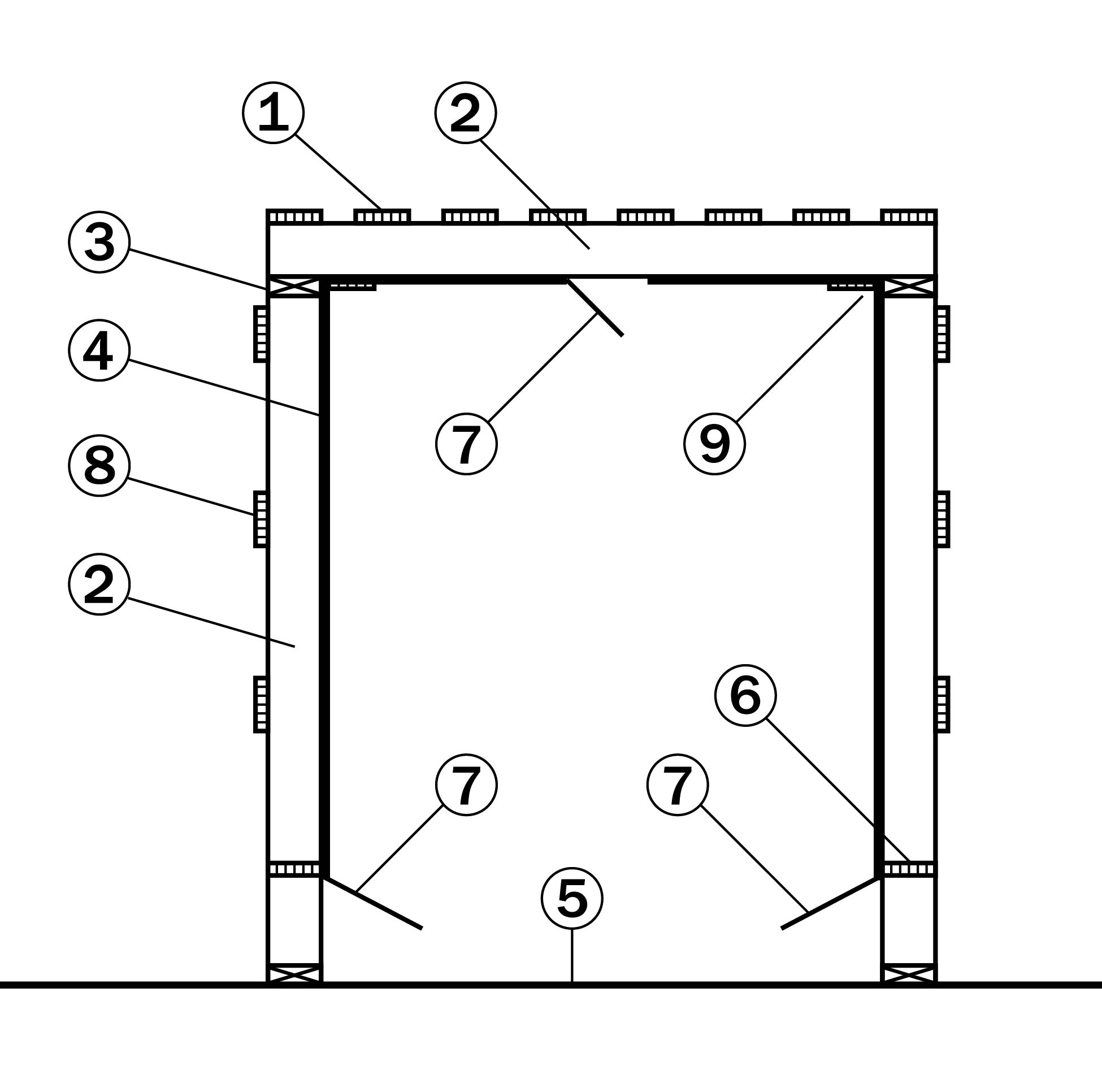
- slats (38 mm × 89 mm (2 in. × 4 in.)), spaced 75 mm (3 in.) apart
- framing (38 mm × 140 mm (2 in. × 6 in.)), spaced 600 mm (25 in.) apart
- plate (38 mm × 140 mm (2 in. × 6 in.))
- duct lining (1⁄2-in. plywood)
- mow floor
- blocking (19 mm × 140 mm (1 in. × 6 in.))
- air control door (200 mm (8 in.))
- slats (19 mm × 89 mm (1 in. × 4 in.)), spaced 300 mm (12 in.) on centre
- continuous nailer (19 mm × 89 mm (1 in. × 4 in.))
The main air plenum is a rectangular, plywood-lined, airtight duct that is smooth on the interior to allow unrestricted airflow. Air control doors located along the base of the duct walls and on top of the duct direct air into the hay. The doors also control the airflow to different sections of the mow.
The main air plenum is located through the centre section of the hay storage or along one side. Side‑wall main ducts are used with narrower mows — less than 7.3 m (24 ft) wide. The advantage of side-wall ducts is the ease of working around them in the mow. However, it is more difficult to make side-wall duct systems airtight.
Unlined ducts can be used, provided the distance the air has to travel to the perimeter of the mow is equal over the entire mow. However, the flexibility of drying sections of the mow separately is lost with an unlined duct. A hay duct, constructed of hay sides and a plank top, can also be used as a main duct with the same limitations as the unlined duct.
The layout of the air duct and slatted floor allow for equal travel distance for the air to move to the outside perimeter of the mow (Figure 4). Therefore, if the distance from the main duct air slot to the outside walls and to the mow top is equal, a slatted floor is not necessary.
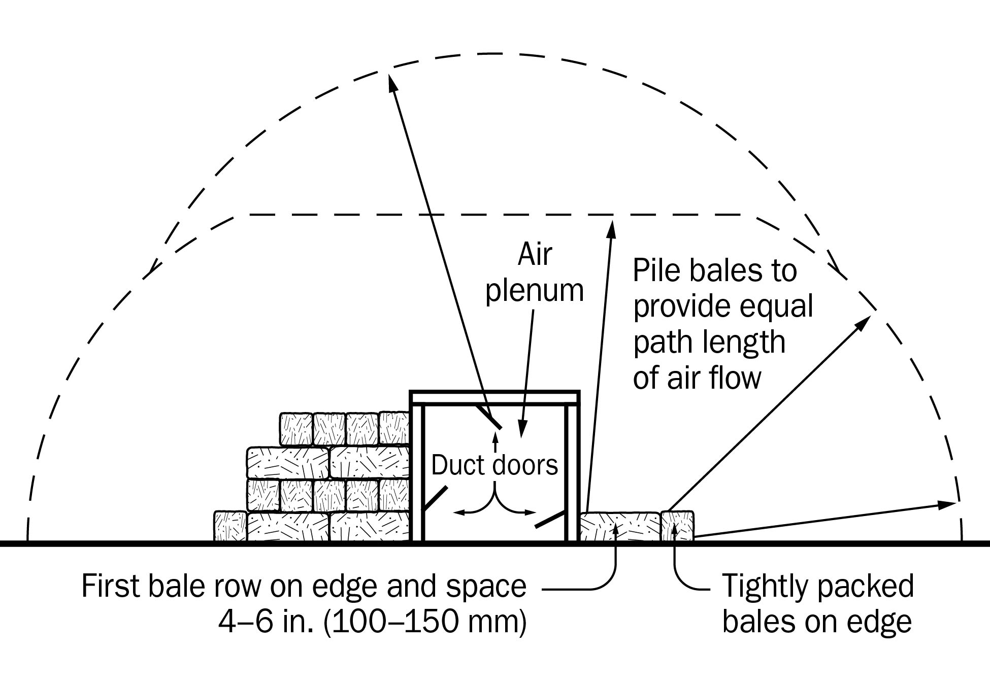
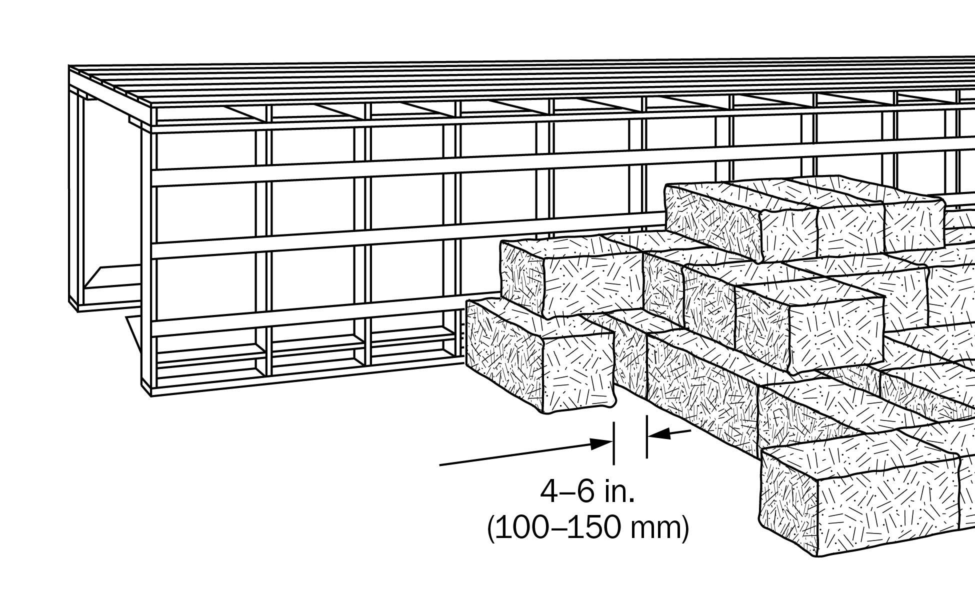
Provide as a minimum, a single row of bales placed on edge at right angles to the duct, with 100–150-mm (4–6-in.) spaces between them. These air channels will lessen the pressure around the duct. Beyond the first bale row spacing, provide more bale row openings to achieve the equal air travel distance through the solid packed bales to the mow perimeter (Figure 5).
Never use slatted floors where the distance from the main duct to the outside of the mow is less than to the top of the mow, as the air will short-circuit through the sides of the mow.
System design
Consider the following when designing the system:
- Size the main air duct to provide a minimum of 0.09 m2 (1 ft2) of cross-sectional area for every 470 L/s (1,000 cfm) of fan capacity.
- Size air control doors to create a maximum air velocity through the opening of 2.5 m/s (500 fpm) or provide 0.18 m2 (2 ft2) of opening area for every 470 L/s (1,000 cfm) of fan capacity.
- Do not install air control doors closer that 2.4 m (8 ft) to the ends of the main duct. The first 2.4 m (8 ft) of duct next to the fan should always be tightly sheathed.
- Provide 0.18 m2 (2 ft2) of opening from the mow to the outside for every 470 L/s (1,000 cfm) of fan capacity for exhaust air discharge.
Harvesting and filling
The hay dryer is designed to dry tough or damp hay but not wet hay. Field dry the hay to an average moisture content of 25% before baling. Hay with a high grass content may be baled with a slightly higher moisture level. Bale the hay at normal baler tension and make slight adjustments, if necessary, for high moisture content. Remember that the bales will shrink slightly during the drying process.
Place the hay uniformly over the entire mow section being dried. Pack the mow tightly with the bottom layer of bales on edge. The upper remaining layers of bales may be placed flat with alternate layers at right angles to each other.
Start the fan once the loading of the mow commences. Place enough hay on the dryer the first day to adequately cover the floor and duct section. This ensures that effective drying can begin.
Operation of dryer
Once the fan is started, run it continuously until the hay is dry.
When the hay at the top of the mow appears fully dry (minimum of 7 days after the last hay is put in the mow), turn the fan off overnight. Start it again the next morning, with someone in the mow to check for warm air or steam escaping.
If heating is evident, run the fan for a day or two and recheck.
If no heating is evident after three checks, consider the hay dry.
Cost
The capital cost of the hay drying system varies, depending on the type and size of the system, and the available materials and labour.
Operating costs depend on hay moisture content and weather conditions during the drying period. Expect an average energy usage of 55–83 kWh/tonne (50–75 kWh/ton).
This fact sheet was updated by Daniel Ward, P. Eng., poultry housing and equipment, OMAFRA.