On-farm liquid nutrient transfer systems
Learn how to plan, design or construct on-farm liquid nutrient transfer systems. This technical information is for engineers, contractors and farm operators.
ISSN 1198-712X, Published October 2022
Introduction
Liquid nutrient transfer systems are critical components of on-farm nutrient management. They are designed to transfer manure and/or agricultural source materials to a permanent storage facility easily and efficiently. Liquid transfer systems include buried pipe, pipe connections, fittings and penetrations through walls that can cause pollution of surface and groundwater if leakage occurs. This fact sheet is intended as a guide for engineers, contractors, farm operators and others who plan, design or construct on-farm liquid nutrient transfer systems. It outlines common practices and techniques.
Nutrient Management Act, 2002, and regulation
Sections 87 and 88 of O. Reg. 267/03, under the Nutrient Management Act, 2002 (NMA), set out the requirements for liquid nutrient transfer systems.
Transfer systems convey liquid nutrients between livestock housing and permanent liquid storage facilities, while preventing leakage to surface or groundwater. Nutrients include liquid manure, milkhouse washwater, run-off containing nutrients and non-agricultural source material (NASM), where it applies.
Transfer systems include all piping, connections, associated fittings and couplings to prevent leakage. Liquid flush return pipes and milkhouse washwater lines to permanent nutrient storages are considered transfer systems and are subject to the same regulatory requirements as a liquid manure transfer system.
NMA regulation and transfer systems
Transfer systems are grouped into three general types:
- gravity flow systems
- pump (pressure) systems
- liquid flush systems
All three types require professional engineering design and engineering site review of the construction. Where a commercial pump system is planned, engineering design is considered completed by the pump manufacturer if the system piping (type, size, operating pressure and gasketed connections) is installed in accordance with the manufacturer’s specification and installation guide. In such cases, only a site review of construction is required.
Gravity flow systems
Gravity transfer systems commonly use high-density polyethylene (HDPE) pipe or polyvinyl chloride (PVC) standard dimension ratio (SDR) 35 pipe and fittings. Equivalents approved by a professional engineer are also acceptable. A professional engineer must specify the type and designation of pipe.
Pump (pressure) systems
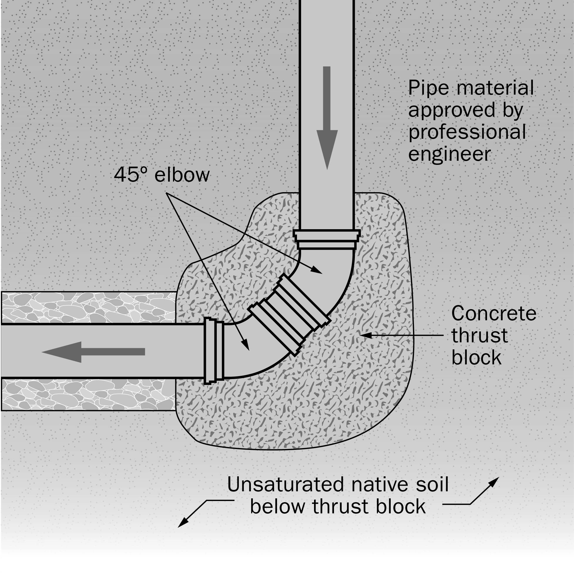
Pump systems must use piping appropriate for the maximum pressure the system can develop. Pump transfer systems commonly use Schedule 40 or 80 PVC or PVC SDR 21 or SDR 26 pipe and fittings. Use mechanical or PVC fittings of the same pressure rating as the approved pipe material. Restrain all fittings using either mechanical restraint couplings or cast-in-place concrete thrust blocks. In a piston pump system, bell-to-spigot mechanical couplers are required at every pipe joint.
Commercial pump systems
Commercial pump systems are used with manure containing bedding materials. Select the pump based on the type and quantity of bedding used.
Use Table 1 as a general guide in correlating pump type to bedding used. These systems include an operation manual outlining installation materials and methods, system features and maintenance procedures, as well as pump placement, maximum operating pressures and air flush system riser requirements.
| Barn type | Bedding type | Pump type |
|---|---|---|
| Freestall barn (liquid) | sawdust or wood shavings | centrifugal |
| Freestall barn (liquid) | chopped straw | centrifugal |
| Freestall barn (liquid) | long straw | piston |
| Freestall barn (liquid) | sand | piston |
| Tie-stall barn (semi-solid) | sawdust or wood shavings | centrifugal |
| Tie-stall barn (semi-solid) | chopped straw | piston |
| Tie-stall barn (semi-solid) | long straw | piston |
| Tie-stall barn (semi-solid) | sand | piston |
Commercial pump systems specify the size of the discharge pipe and a corresponding pressure rating for pipe material. Table 2 shows working and maximum discharge pressures for pumps handling liquid, semi-solid and solid materials. Once the pump is selected, choose piping to match the pump’s maximum rated discharge pressure.
| Pump type | Normal pump discharge Working pressure |
Maximum pump Discharge pressure |
|---|---|---|
| Liquid | 172 kPa 25 psi |
241–427 kPa 35–62 psi |
| Semi-solid | 306 kPa 44.4 psi |
520–586 kPa 75.5–85 psi |
| Solid | 478 kPa 69.4 psi |
586–813 kPa 85–117.9 psi |
Note: Pressures will vary depending on pump type and model.
Non-commercial pump systems
Non-commercial pump systems are transfer systems that consist of a number of separate components with no specifications for piping materials by a pump manufacturer. These systems must be designed and site reviewed by a professional engineer.
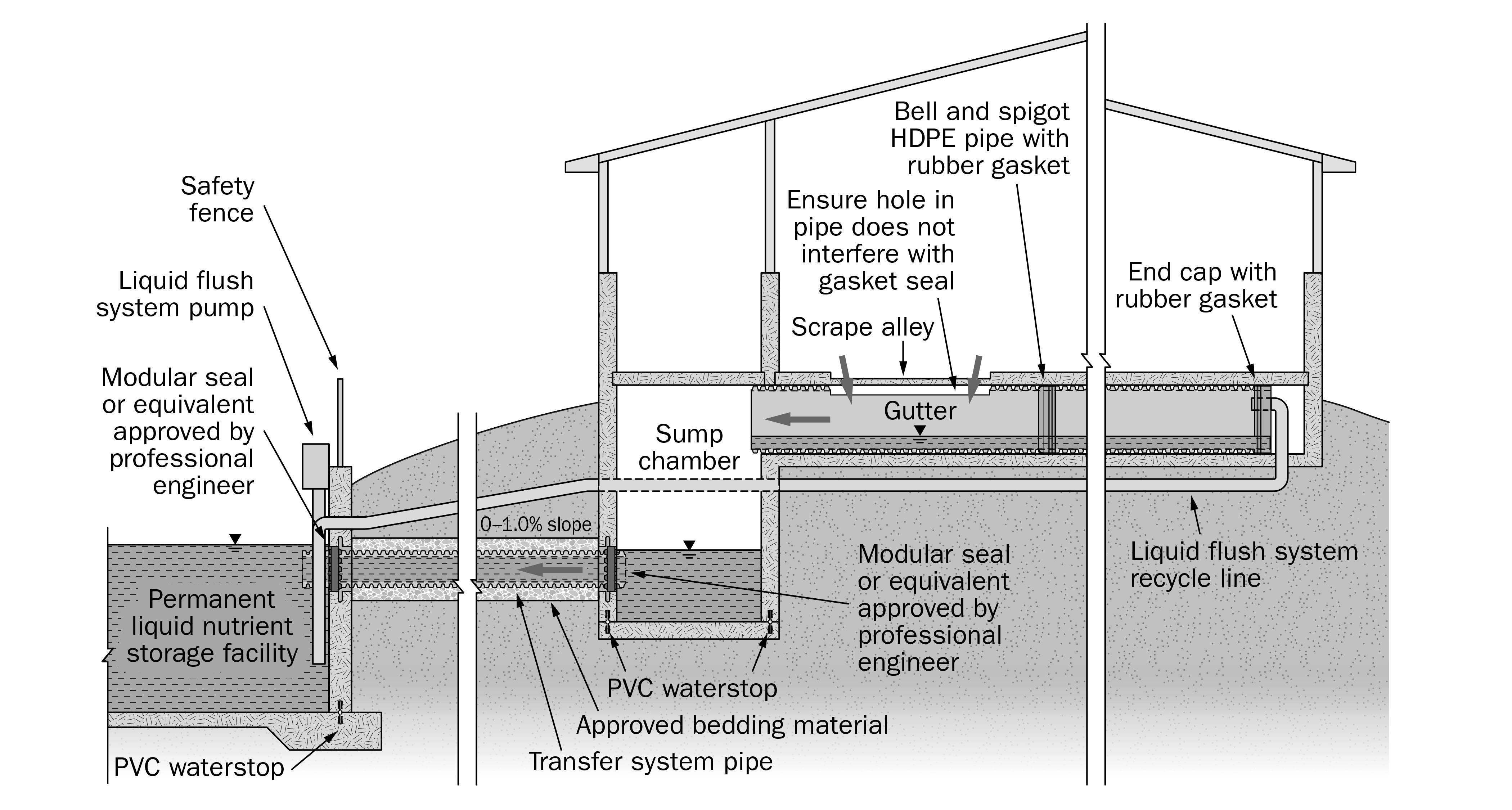
Liquid flush systems
Liquid flush systems are used to reduce solid build‑up of manure in the barn collection gutters when manure is transferred to the permanent liquid storage facility. Typically, a pressurized recycle line from the permanent liquid storage facility enters at the upper end of the gravity collection gutter, flume pipe or scrape alley, and is washed through the collection system. The quantity of water needed to flush the system depends on the gradient of the flush system, bedding type and consistency of the manure. These systems are commonly installed with gravity transfer systems. However, pressure systems are sometimes used.
Transfer pipe connections through storage walls
Liquid nutrient storages
Engineering design drawings for liquid nutrient storages should include details for wall openings where transfer piping will penetrate the storage, sump or holding pit. All openings should include provision for flexible watertight gasket or membrane to prevent leakage and include design details in the structural drawings.
Wall penetrations into reinforced concrete tanks
Wall openings in nutrient storages, sumps and holding pits that accept transfer system piping must be designed by the structural engineer responsible for that structure. The designer of the transfer system should coordinate with the structural engineer regarding wall penetrations to ensure transfer system piping and fittings will prevent leakage at the connection.
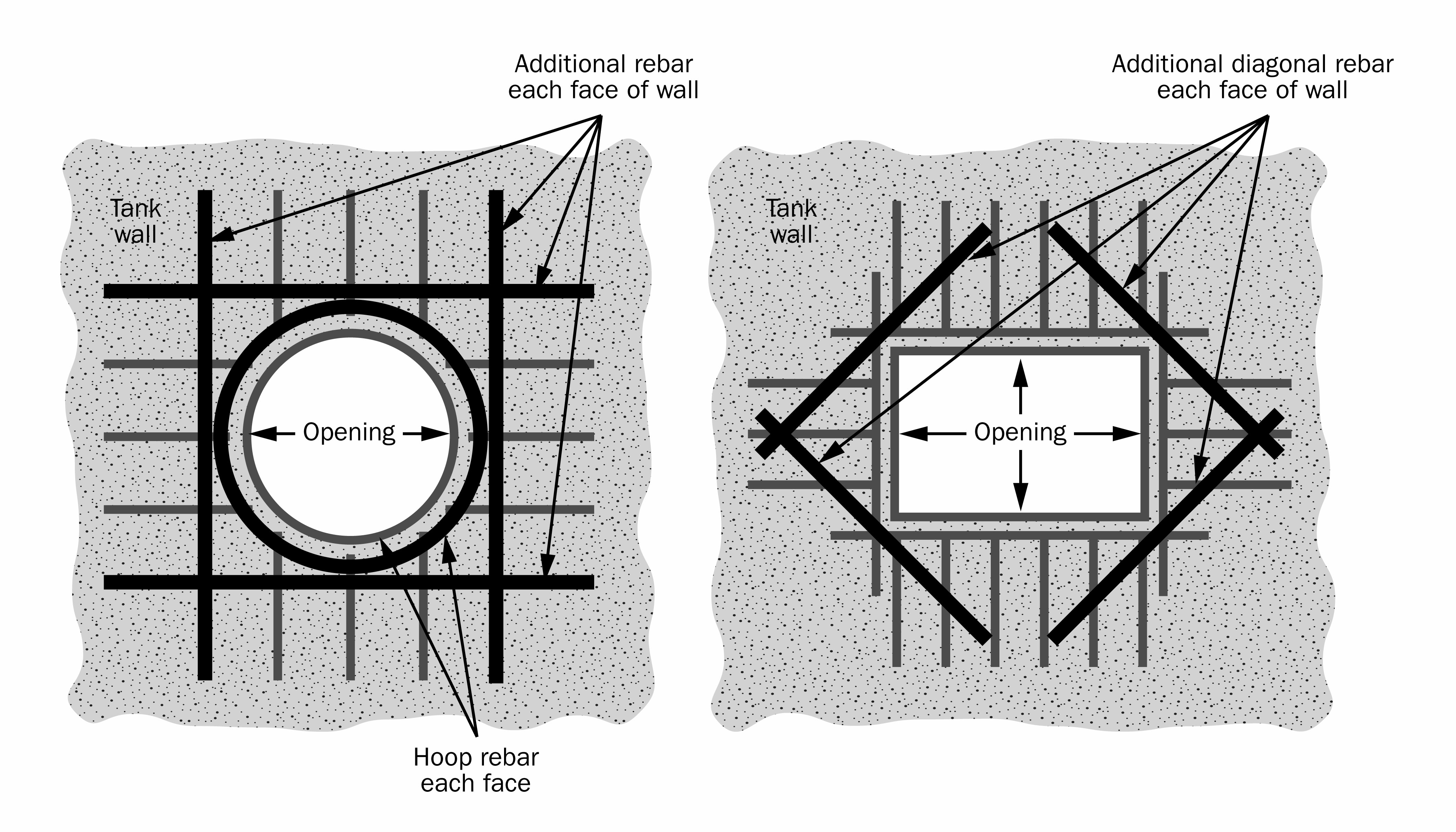
Wall penetrations in reinforced concrete tanks are constructed either during or after construction of the tank itself. This process must ensure the structural integrity of the tank is not compromised. It is preferable to install the pipe sleeves in the forms prior to casting the concrete. Reinforcing steel that is cut to allow placement of the pipe sleeve is replaced with additional reinforcing steel on all sides of the opening (Figure 1).
Two methods of creating a wall penetration are:
Pipe penetration sleeve with anti-seepage collar (during tank construction): The pipe penetration sleeve is a PVC and steel penetration product that is used during the forming of the tank itself. The seal is incorporated as part of the tank around its outer perimeter. A large vertical collar (circular flange) surrounds the outer housing of the sleeve and acts as the anti-seepage mechanism to prevent liquid nutrients from passing between the sleeve and concrete wall.
Use the pipe penetration sleeve with a modular seal system and corrosion-resistant 316 stainless steel hardware to resist acidic nutrients.
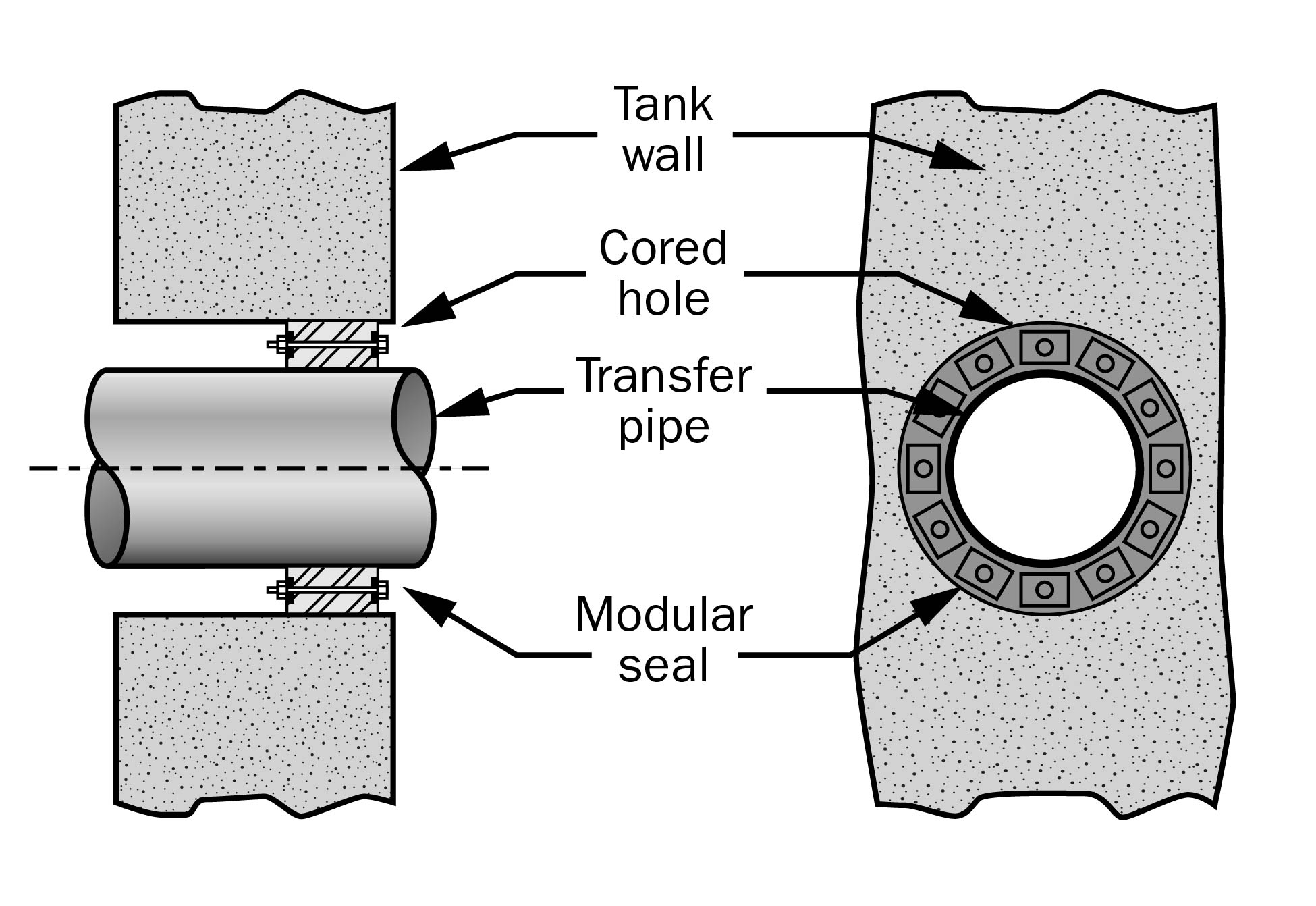
Cored pipe penetration (existing tank): Coring is done on an existing tank where the concrete is fully mature (28-day strength achieved). A hole is drilled into the side of the tank large enough to accommodate the diameter of the specified transfer pipe. A modular seal (or approved equivalent) is installed between the pipe and the wall.
Coring a pipe penetration into an existing structure must be done according to specifications from a structural engineer to ensure that the structural integrity of the wall is maintained at the opening.
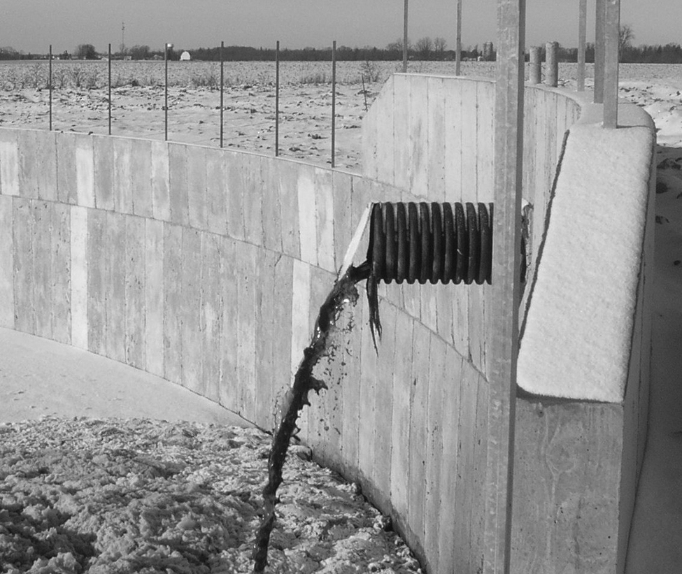
Gravity transfer system discharge over tank wall (above grade)
Gravity transfer systems often discharge liquid nutrients into the primary storage facility over top of the tank wall. These systems may include an additional section of tank wall to secure the pipe or use additional concrete for anchoring (Figure 2).
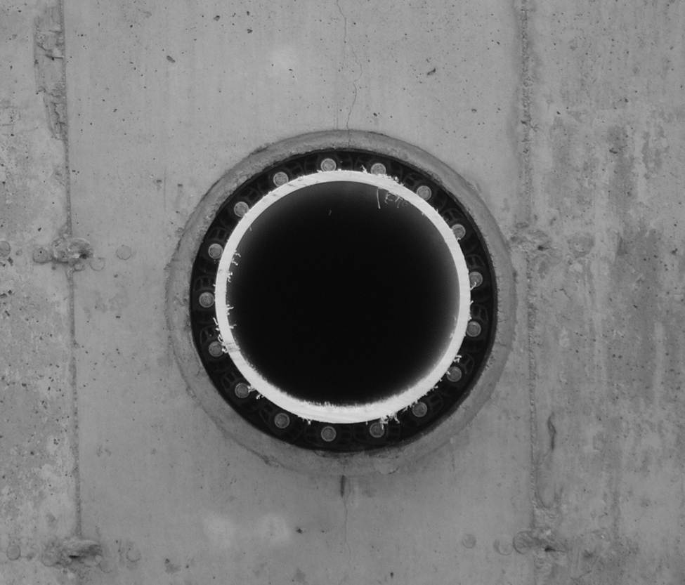
A modular seal contains internal stainless steel hardware components combined with a rubber shell. It is the gasket commonly used with pressure systems for perpendicular pipe penetrations into the tank floor or wall (Figures 3 and 4). Use modular seals in either a penetration sleeve or a cored hole.
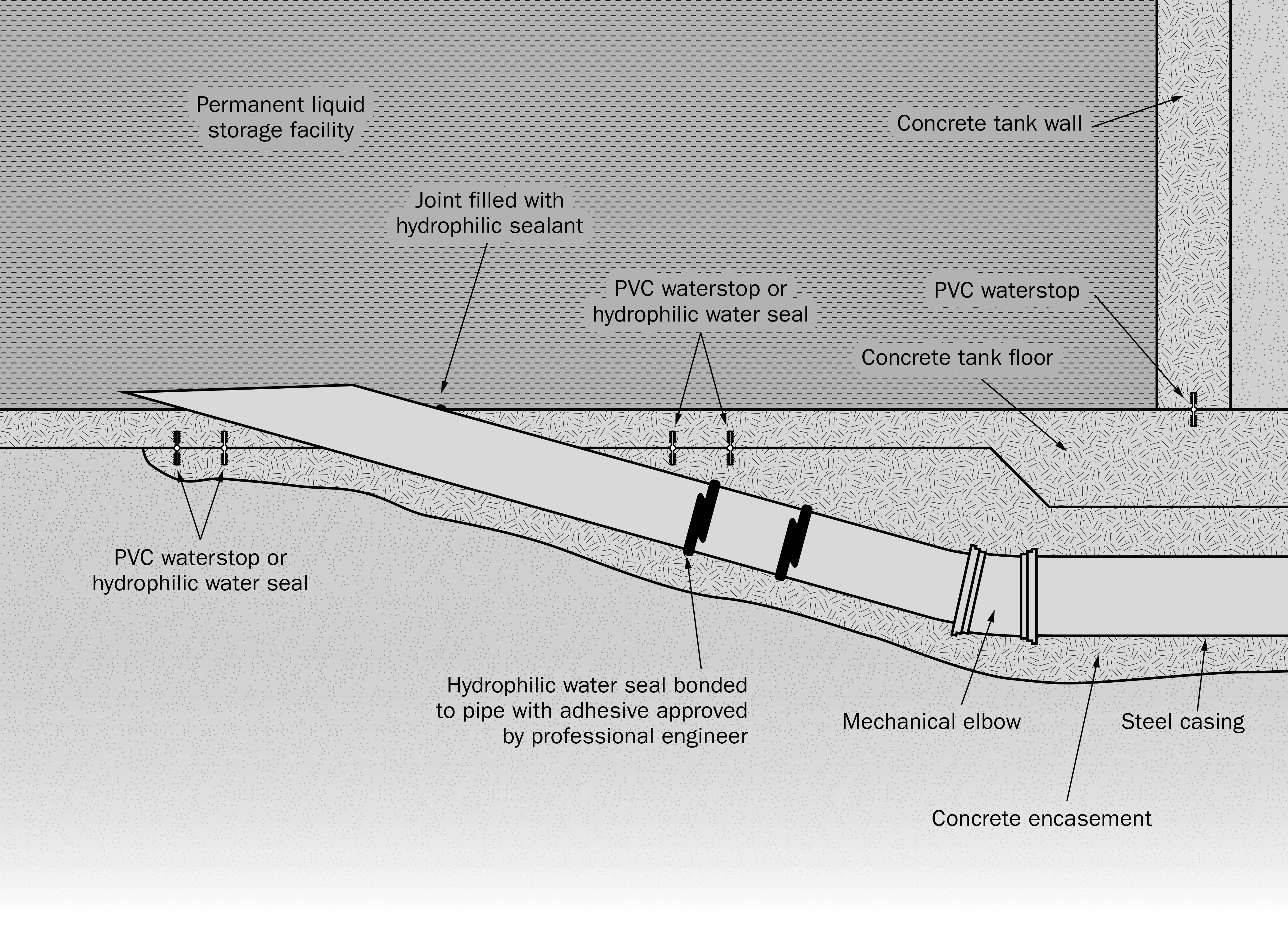
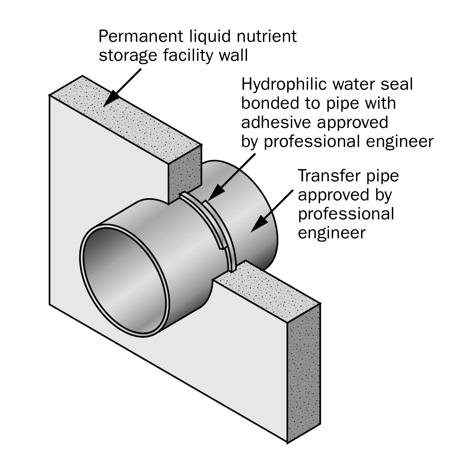
A hydrophilic water seal is used for wall and floor penetrations to accept transfer system piping (Figures 5 and 6). Hydrophilic sealing products can expand to several times their original size and contract as required to compensate for thermal expansion and contraction within the concrete. Choose hydrophilic sealing products without a clay base to resist acidic nutrients. Choice of seal is part of the engineering design of the opening.
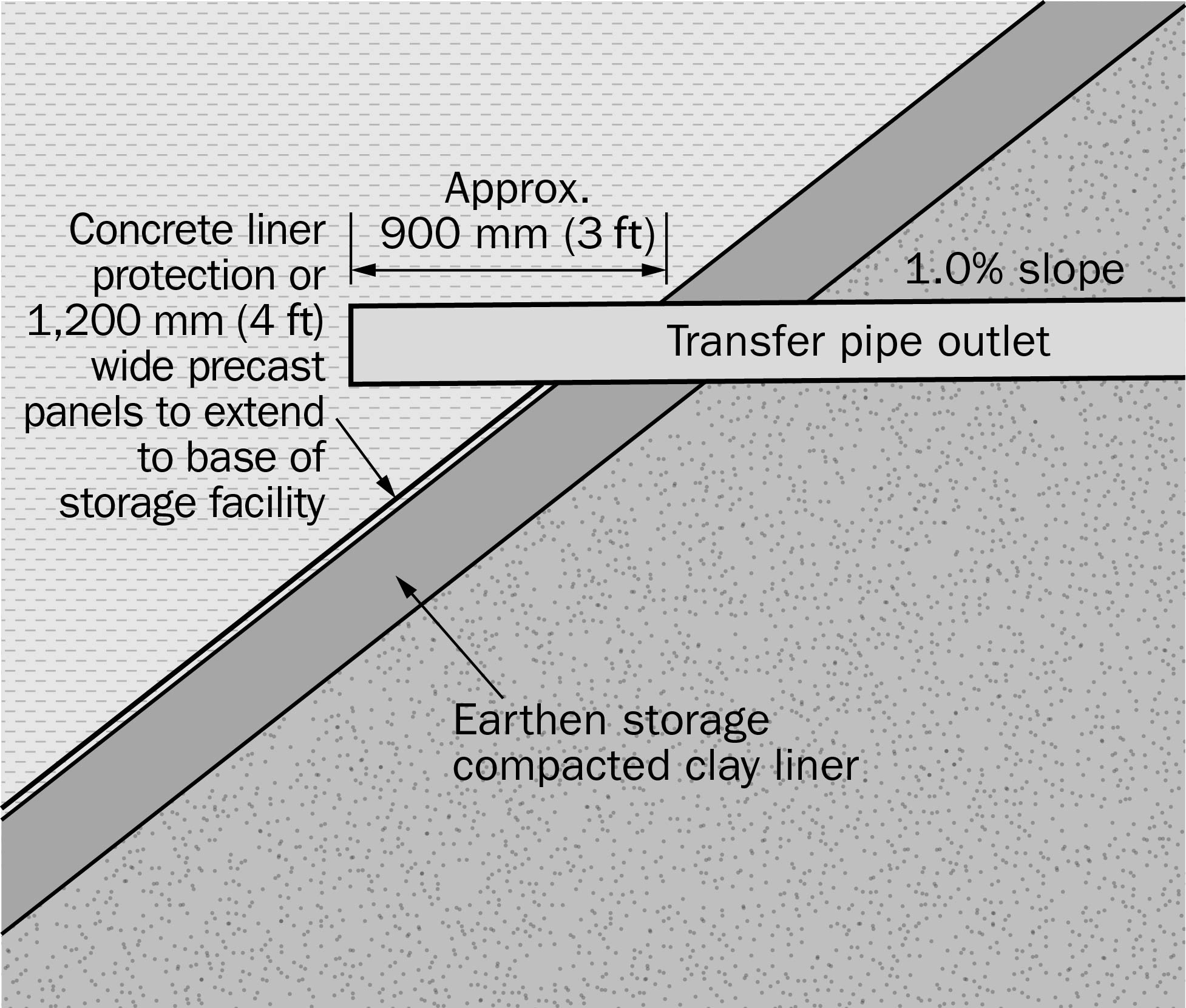
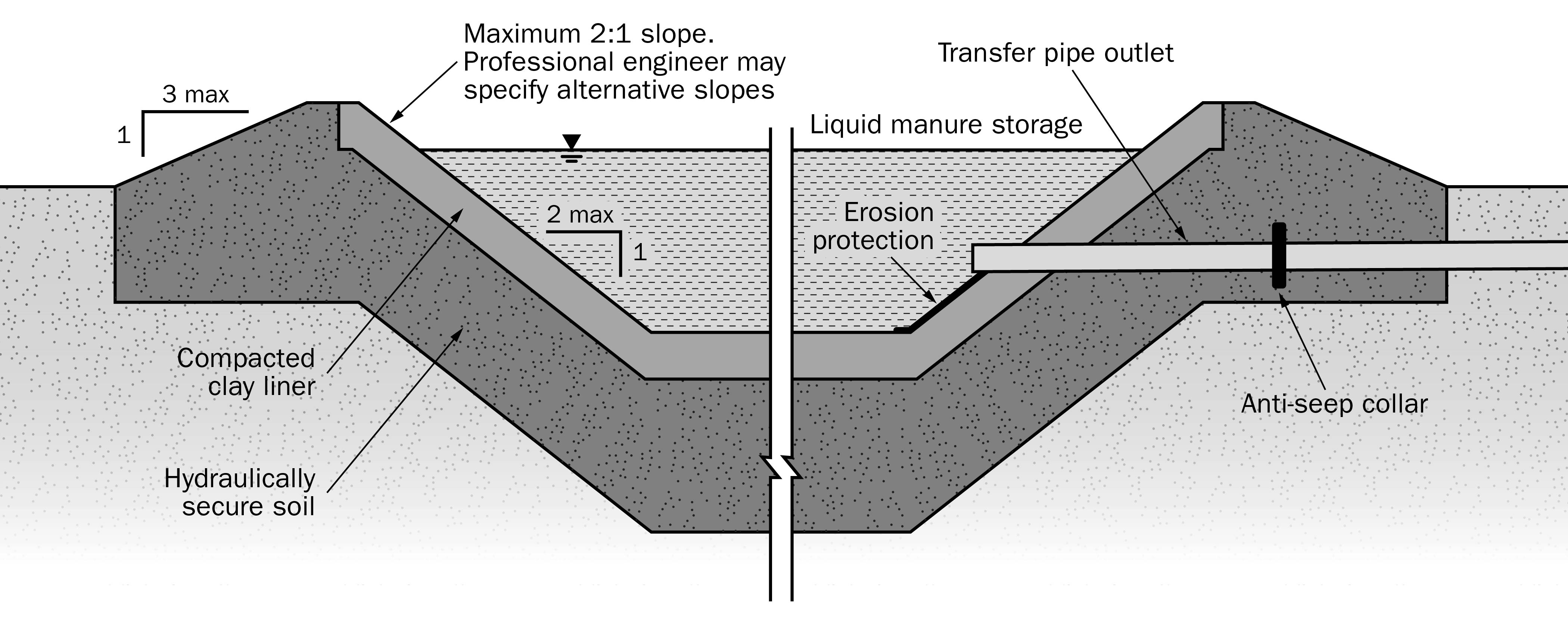
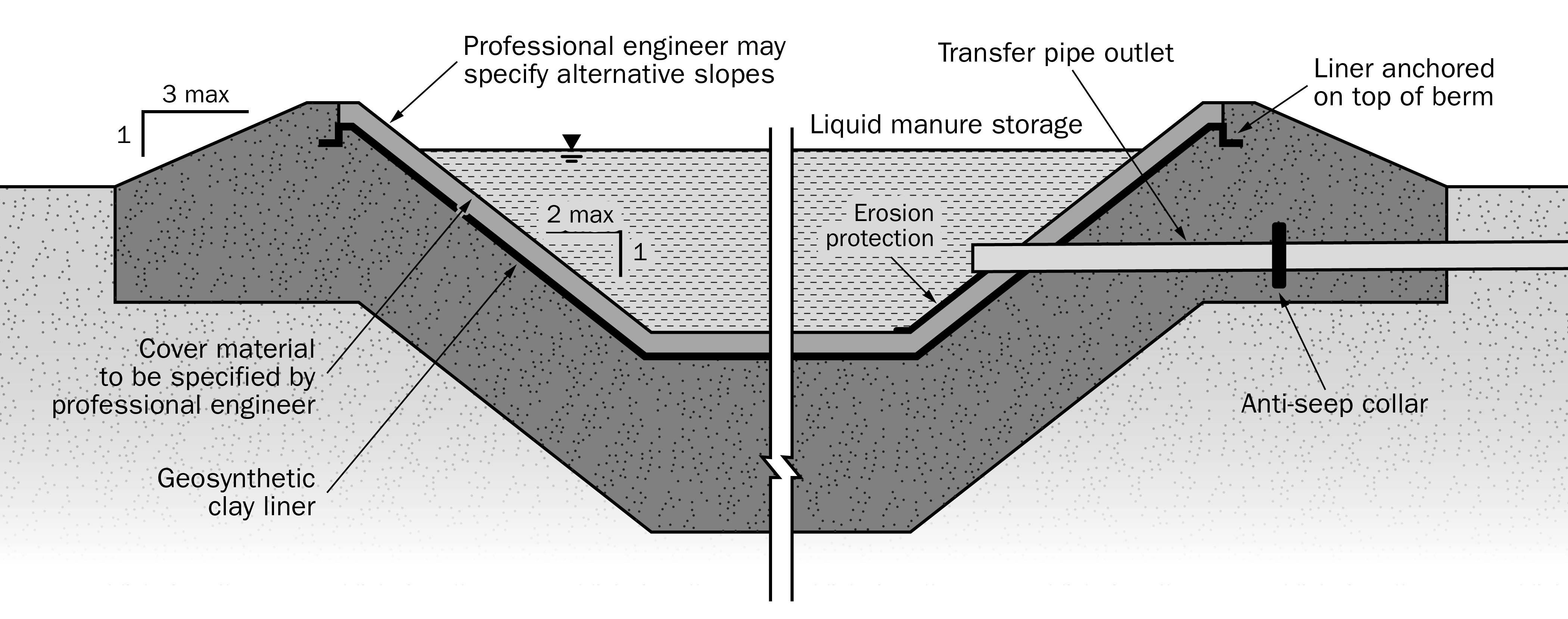
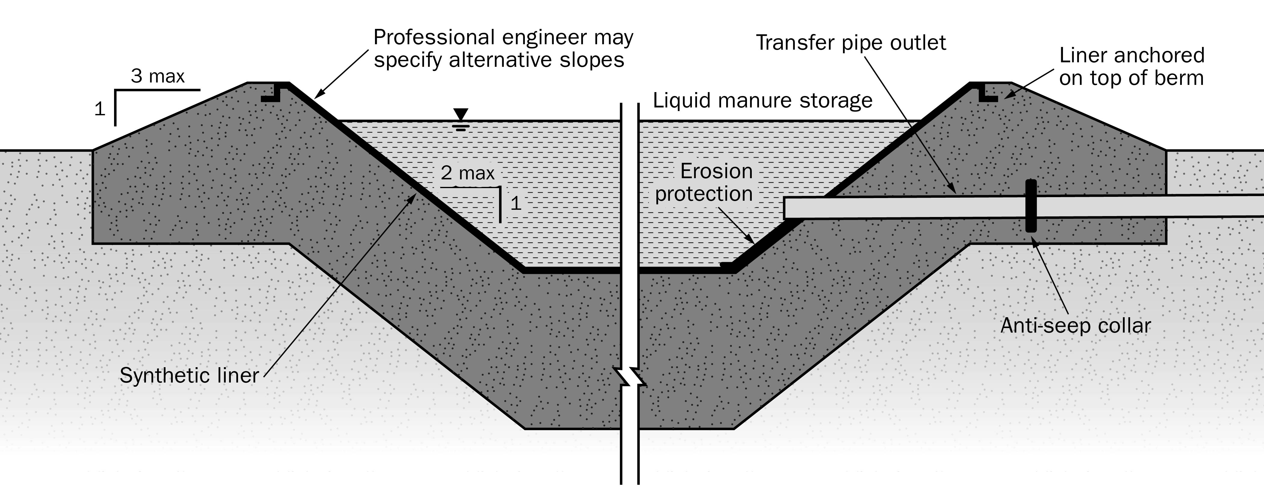
Earthen storages
Construct transfer systems outletting into an earthen storage in accordance with the NMA and Regulation. Use the same materials as any other liquid nutrient transfer system. Compact earthen floor, sidewalls and berms according to the design specifications. Remove tile drains from around the perimeter of the structure in accordance with the Regulation and re-route to an outlet. Engage a licensed tile drainage contractor to conduct this work.
For compacted soil liners, construct pipe penetrations using granular bentonite as a sealant around the penetration area (Figures 7 and 9). Anchor pipes entering the earthen storage by constructing a concrete headwall. Attach the pipe to the headwall using a modular seal. Seal the headwall against the liner in a manner approved by a professional engineer.
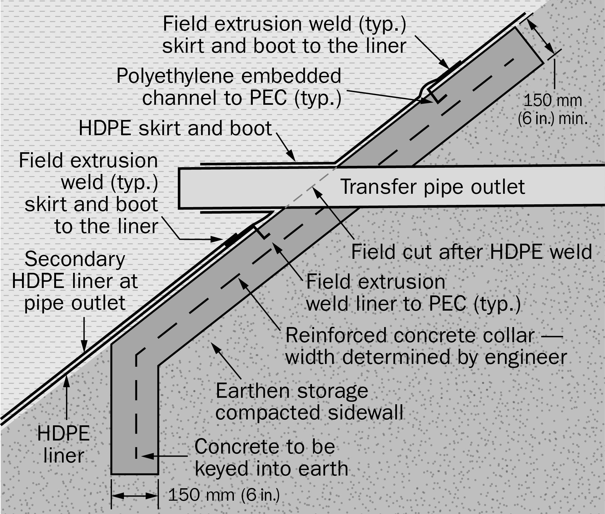
With geosynthetic liners, use a bentonite-based primer as a sealant around pipe penetrations, with a “boot” constructed around the pipe (Figures 8 and 10). For a fully synthetic liner, seal pipe penetrations by vulcanizing additional liner material and a “boot” around the incoming pipe (Figures 8 and 11).
Containing runoff from solid nutrient storages and cattle yards
Transfer system piping is one method to manage runoff from uncovered solid nutrient storages and cattle yards. All pipe materials, fittings and sealing devices used for liquid nutrient transfer systems can be used. Construct the solid storage or cattle yard so that liquid nutrients and incident rainfall drain to the inlet of the transfer piping.
Transfer system shut-off devices
In the event of system failure and for maintenance purposes, it is necessary to be able to stop the flow in a liquid transfer system. In both gravity and pressure systems, guillotine valves have proven most effective for this purpose. In pressure systems, place shut-off valves before and after the pump; this feature is often built into the pump itself. All shut-off devices are part of the engineering design for the transfer system. Where the surface of stored liquid in the tank is at a higher elevation than the barn floor or collection area, install an additional shut-off valve between the pump and tank wall.
To avoid the negative effects of water hammer on the pipeline, install air/vacuum relief valves at all high points in pressurized systems.
Common dairy facility transfer systems
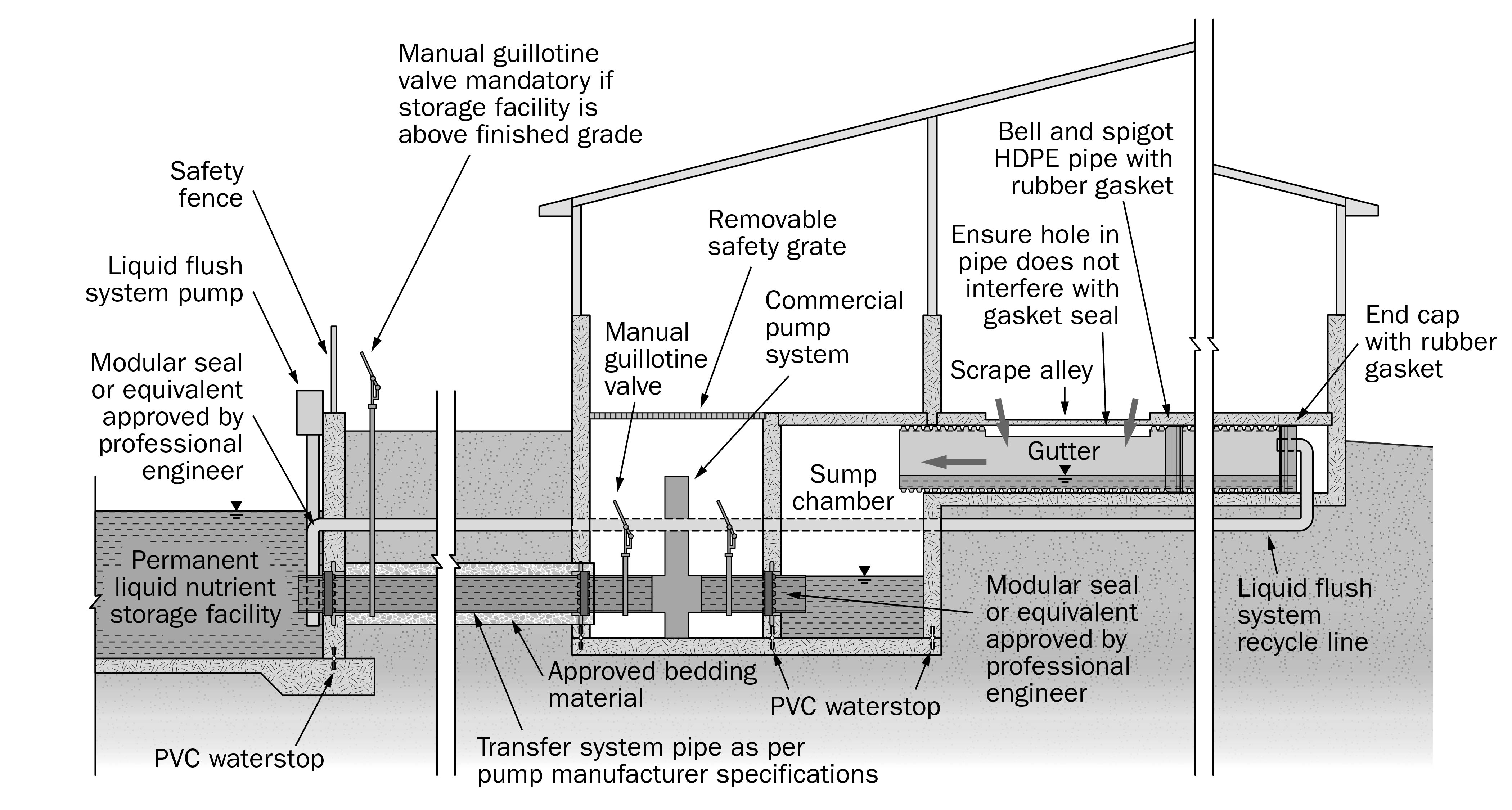
Dairy operations that manage manure as a liquid generally use either a gravity (Figure 12) or commercial pump (Figure 13) transfer system.
Gravity systems are passive, using the elevation difference to transfer manure between the livestock facility and the permanent liquid storage. Where the elevation difference does not permit gravity flow, pump systems transfer nutrients.
Common swine facility transfer systems
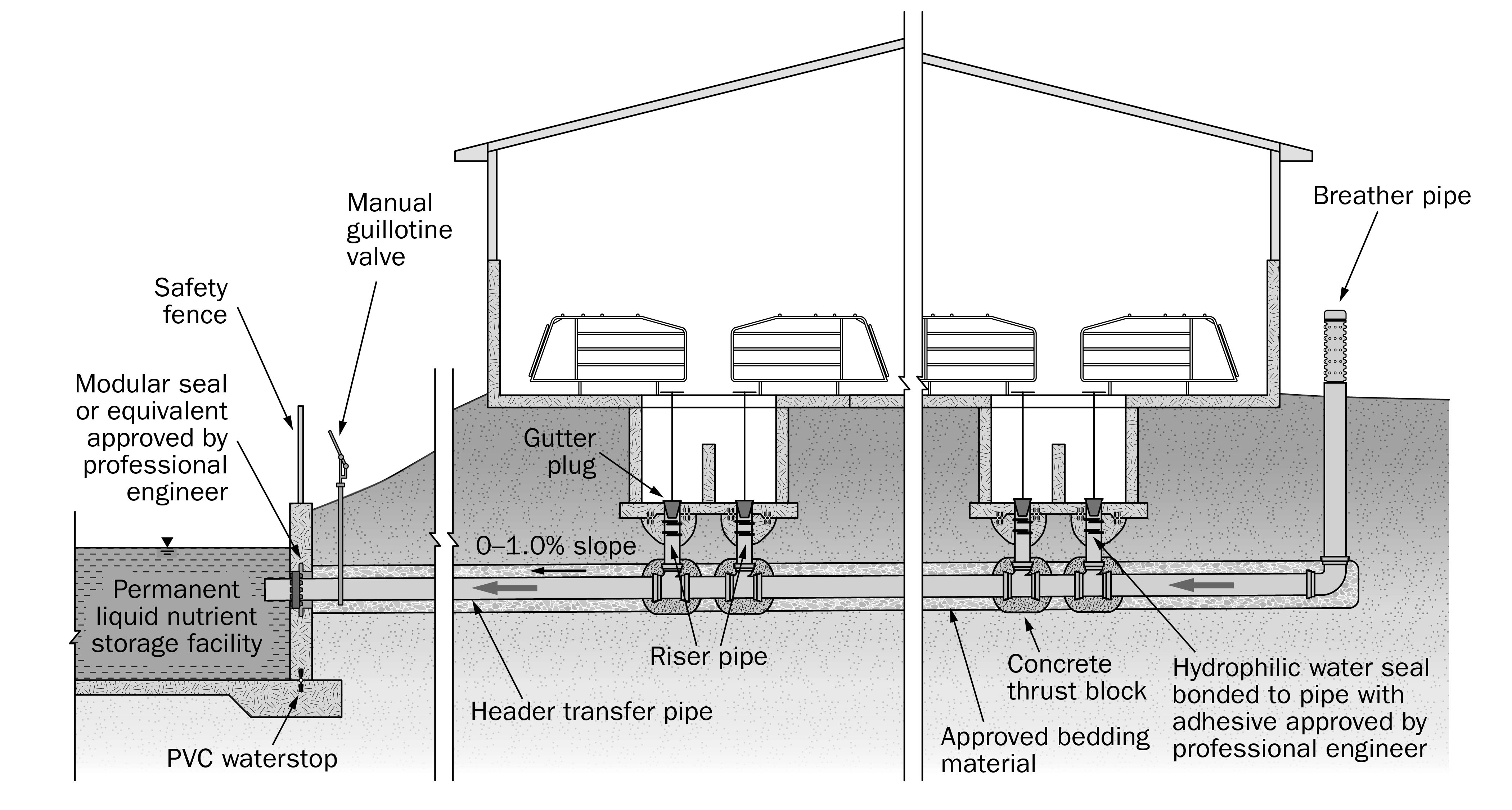
Transfer systems for liquid manure in swine operations follow the same principles as their dairy counterparts, yet configurations are different to accommodate swine housing requirements. Most facilities use under-barn storage for a few weeks before transferring the liquid nutrients to a permanent storage (Figure 14).
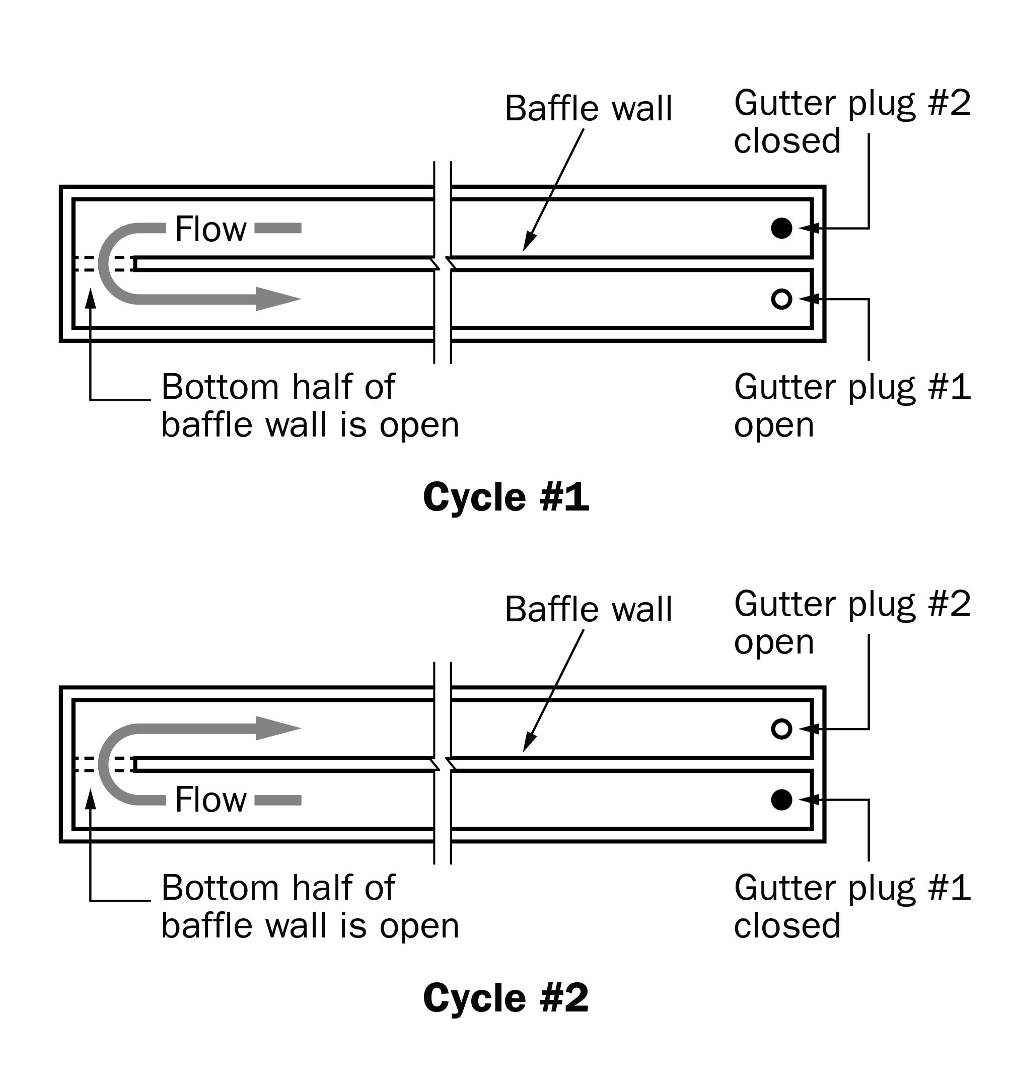
A hairpin configuration (“racetrack”) with double pull plugs is often used in these barns (Figure 15). Two outlet pipes, each fitted with a rubber plug, are separated by a baffle wall, with an opening at the opposite end. Plugs are alternately pulled to drain the holding tank at the end of each holding cycle. This flow reversal reduces solids build-up in the system.
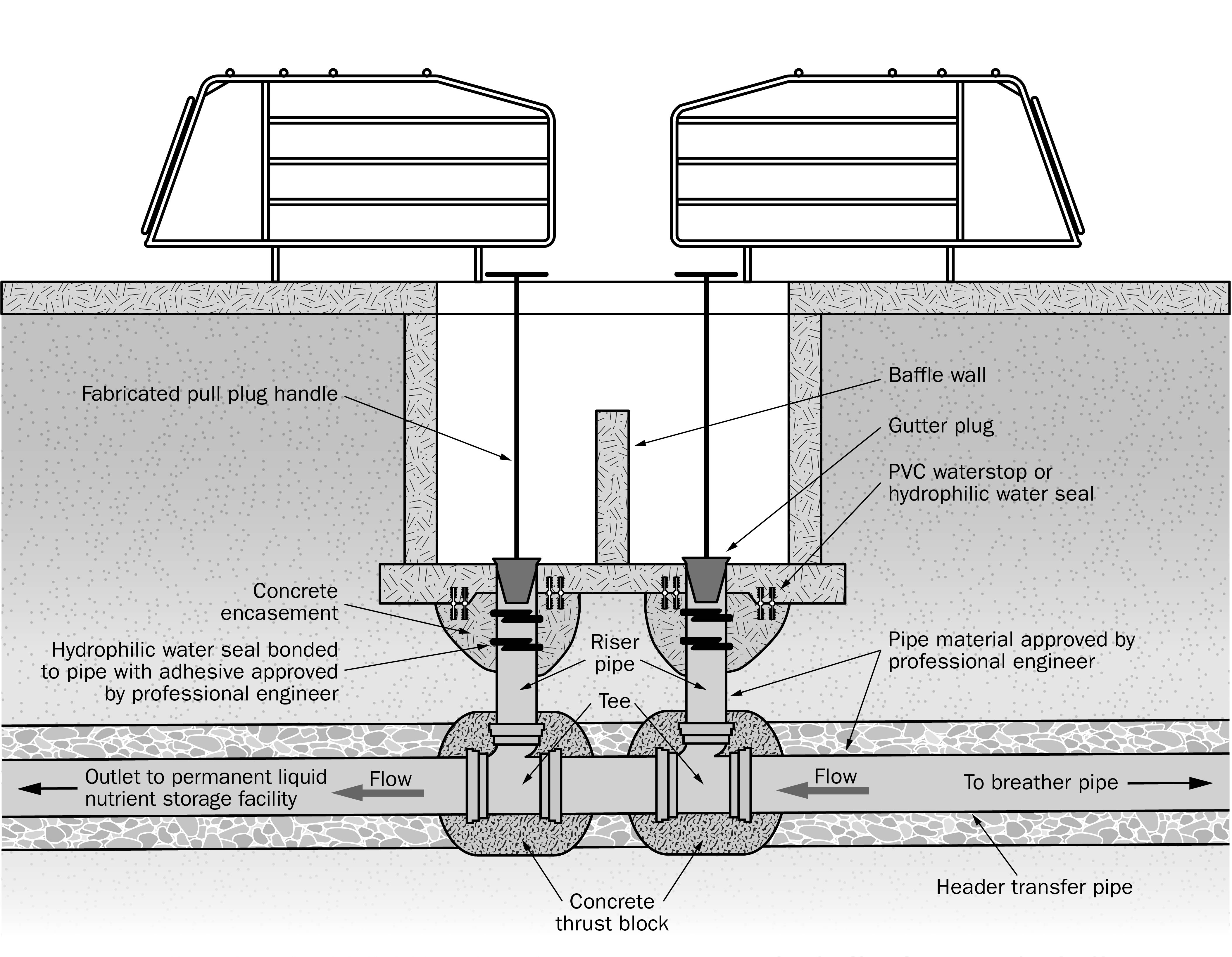
All pipe connections, compatible fittings and couplings are used for both riser and header pipes. Individual riser pipes include a watertight connection such as a hydrophilic water seal (Figure 16) between the pipe and holding tank floor.
There are several other storage methods used in swine facilities, but under-barn storage is the most common. This involves locating a concrete tank below the barn to serve as both a building foundation and a permanent liquid nutrient storage. At intervals, manure is pumped from the tank directly to a spreader and field applied. Where under-barn permanent storage is used, a transfer system is not required.
Best practices for installation
The following best practices are important to ensure that transfer piping and connections remain undisturbed after construction.
- Follow OPSS 514 for Trenching, Backfilling and Compacting. This is the construction specification used in Ontario for the installation of underground infrastructure. The specification requires bedding materials be placed in 200-mm (8-in.) lifts simultaneously (both sides of the pipe), compacted to 95% maximum dry density before a subsequent layer is placed.
- Follow the criteria for a safety trench – OPSD 802.010 (flexible pipe) and OPSD 802.030 (rigid pipe).
- Use granular material for pipe bedding (for example, Granular A, sand, ¾-in. crushed stone).
- Pour concrete thrust blocks at elbows (Figure 17) or use mechanical restraints.
- Select pipe material based on system type.
- Make all wall penetrations perpendicular to the wall.
- Firmly support pipes on compacted bedding and backfill material. Do not rely on the modular seal for support.
Best practices for preparing the trench for pipe
The following best practices are important to ensure trenching meets both design and safety requirements.
- Cut transfer system piping trenches to the design depth, true to line and gradient.
- Shape or groove the trench bottom to bed, fit and secure the pipe.
- Ensure trench width provides sufficient space to connect pipe joints and do other necessary work in the trench. See OPSD 802.010 (flexible pipe) and OPSD 802.030 (rigid pipe).
- Start trench work at the outlet and work upslope.
- Ensure width of trench (measured at top of pipe) provides enough clearance between the trench wall and where the pipe is laid for blinding material to fill the space under the haunch of the pipe to provide lateral support.
- Protect pipe from floating in wet soil conditions.
- Add cleanouts on long pipe runs.
Best practices for blinding and backfilling the trench
The following best practices are important to ensure piping is installed and the trench backfilled as specified.
- Before backfilling the trench, have a professional engineer perform a site review of installed piping.
- Re-align any piping that is misaligned from trench wall cave-ins or from foreign materials before blinding.
Blinding
- Blinding ensures the pipe and connections remain in place and provides adequate cover to protect the pipe from the backfilling operation.
- Blind all transfer pipes by placing prescribed material around the pipe before backfilling, especially where bulk dumping of backfill into the trench occurs.
- Blind the pipe immediately after installation by hand shovel or mechanical means, ensuring the pipe remains in place.
- Compact both the bedding and blinding material along the sidewalls of the pipe.
Backfilling
- Carefully backfill the trench with excavated material placed so that the pipe is not damaged or displaced.
- Backfill any open trench at the end of each day.
- Fill the trench to a level sufficiently above finish grade to allow for settlement.
- Maintain a minimum frost cover over pipelines or insulate to protect against frost.
Considerations for gravity vs. pressure systems
The professional engineer responsible for the livestock facility (and also the permanent storage) should assess the options for gravity vs. pressure system at the design stage. Opportunities may arise to relocate new facilities and thus avoid using a pump transfer system. Have the professional engineer assess for:
- elevation difference due to topography or land grading
- distance from livestock housing facility to permanent storage
- ability of liquid nutrients to flow to the storage via pipe without pressurizing the system
Summary
Liquid nutrient transfer systems are critical components of on-farm nutrient management. They involve buried pipe that, together with pipe connections, fittings and penetrations through walls, can cause major pollution of surface and groundwater if leakage occurs. It is imperative that transfer systems be designed and site-reviewed by a professional engineer and constructed to the design specifications to ensure good practice and avoid leakage or system failure.
This document is intended only as a guide to outline common practices and techniques. It is not intended to represent specific design information.
This fact sheet was written by J.B. Arnold, P. Eng., environmental engineer, OMAFRA and R. Brunke, P. Eng., engineer, nutrient management, OMAFRA, Dietrich Engineering Limited and Conestoga-Rovers and Associates (CRA), Waterloo, Ontario.