Forced-air cooling systems for fresh Ontario fruits and vegetables
Learn how to choose, design and manage three types of forced-air cooling (FAC) systems. This technical information is for commercial crop producers in Ontario.
ISSN 1198-712X, Published August 2014
Introduction
This fact sheet describes how to choose, design and manage three types of forced-air cooling (FAC) systems:
- tunnel horizontal airflow
- column vertical airflow
- serpentine vertical/horizontal airflow
Advantages/disadvantages of FAC systems
Tunnel horizontal airflow systems
Advantages
- works with most container types if there are enough side vents
- no limit to the total number of pairs of side-slotted bins/pallets cooled at once
- cooling air travels only the width of one pallet (1–1.2 m or 40–48 in.)
Disadvantages
- of all the FAC systems, requires the most floor area per kg of produce cooled
- of all the FAC systems, has the most sites where cooling air can short-circuit
- space is required between pallets and walls or adjacent tunnels
Column vertical airflow systems
Advantages
- requires a mid-range floor area per kg of produce cooled
- suited to small farms with a wide variety of produce to cool
- of all FAC systems, creates the least number of sites where cooling air can short-circuit
Disadvantages
- all sides of pallet not against the cooling wall must be covered to prevent air from short-circuiting
- only suitable for bottom-slot reusable plastic containers (RPC)
- of all FAC systems, cooling air travels the furthest through produce — up to about 2 m (6.5 ft) — slowing cooling
Serpentine vertical/horizontal airflow systems
Advantages
- of all FAC systems, requires the least floor area per kg of produce cooled
- cooling air travels only through bin depth (0.4–0.6 m or 15–24 in.)
- best for cooling bulk produce before packing
Disadvantages
- bins must have floor vents; any side vents must be blocked
- some cooling air will short-circuit on top bins
- forklift openings restrict airflow and limit how far bins can be stacked out from the wall
Cool soon after harvest
Horticultural crops are living organisms after harvest and must remain alive and healthy until they are processed or consumed
Of these factors, produce temperature has the most influence on respiration. Rapid, uniform cooling immediately after harvest to remove field heat helps to slow respiration and provide a longer shelf life. As a rough guide, a one-hour delay in cooling reduces a product’s shelf life by one day. Although this is not true for all crops, it applies to very highly perishable crops during hot weather. Lowering the temperature also reduces the rate of ethylene production and moisture loss, as well as the spread of microorganisms and deterioration from injuries.
Regardless of the system, fans pull refrigerated air through the produce. The convective contact of high-speed refrigerated air with warm produce creates rapid, uniform, predictable cooling. This is unlike room cooling where produce placed in cold storage cools slowly, non-uniformly and unpredictably, mainly by conduction. FAC cooling typically requires 1–10 hr, while room cooling requires 20–100 hr
Forced-air cooling systems
There are three types of FAC systems used in industry (Figure 1).
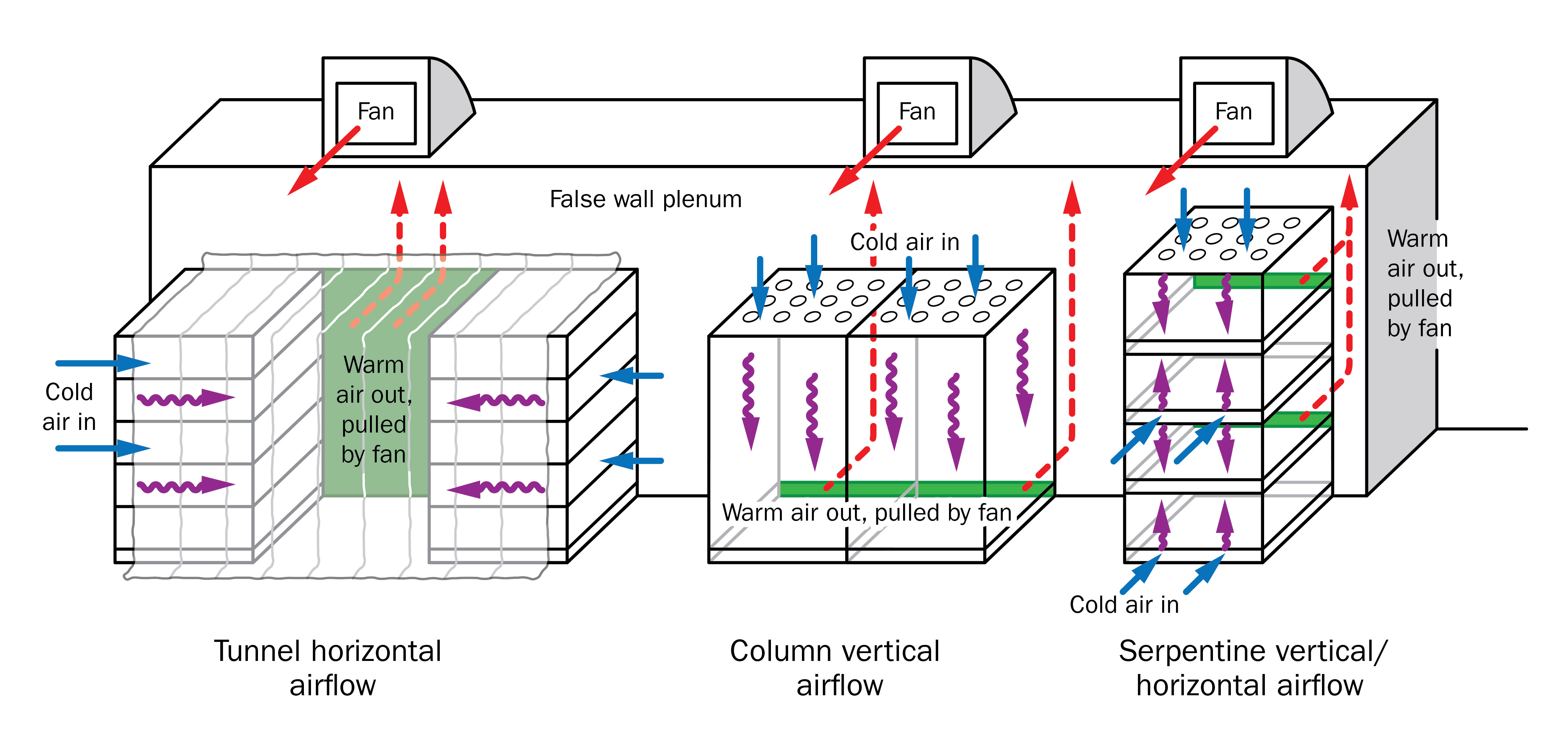
The tunnel horizontal airflow system (Figure 2) is the most common FAC system. Refrigerated air travels horizontally through containers, so align side openings, if possible. Baskets of produce, such as tree fruit, are often packed inside a corrugated cardboard shipping container, which restricts refrigerated airflow. Tapered plastic containers or baskets of fruit on open racks can result in the opposite problem, allowing too much refrigerated air to short-circuit between containers with little cooling occurring.
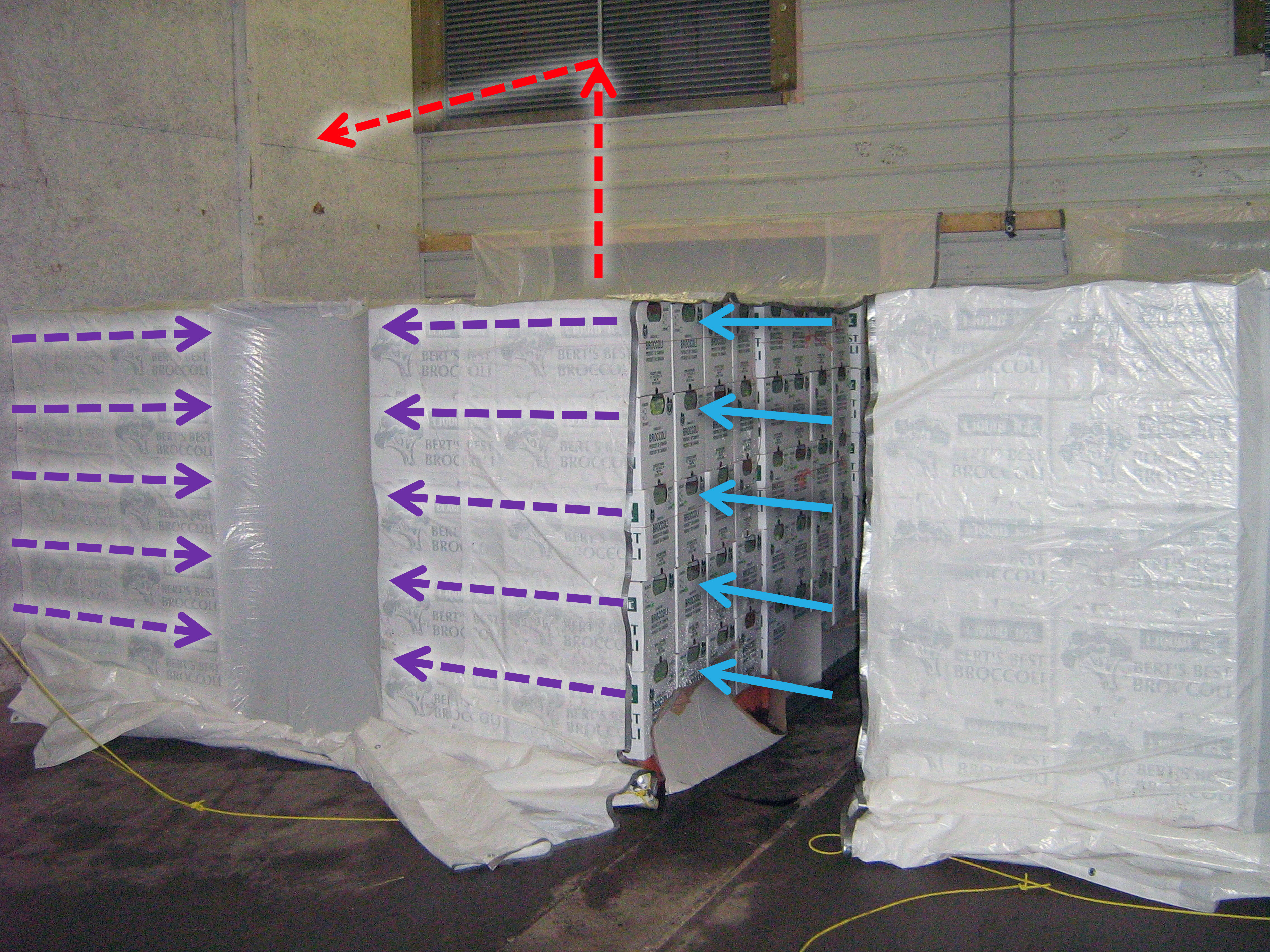
Ideal containers stack tightly on all sides and fill the entire pallet footprint. This minimizes the short-circuiting of air. Corrugated cardboard containers with vent openings that line up or reusable plastic containers (RPCs) on pallets work well. Many growers use plastic bins for handling produce in bulk. One-way forklift entry bins are best, since two-way forklift entry bins allow refrigerated air to short-circuit.
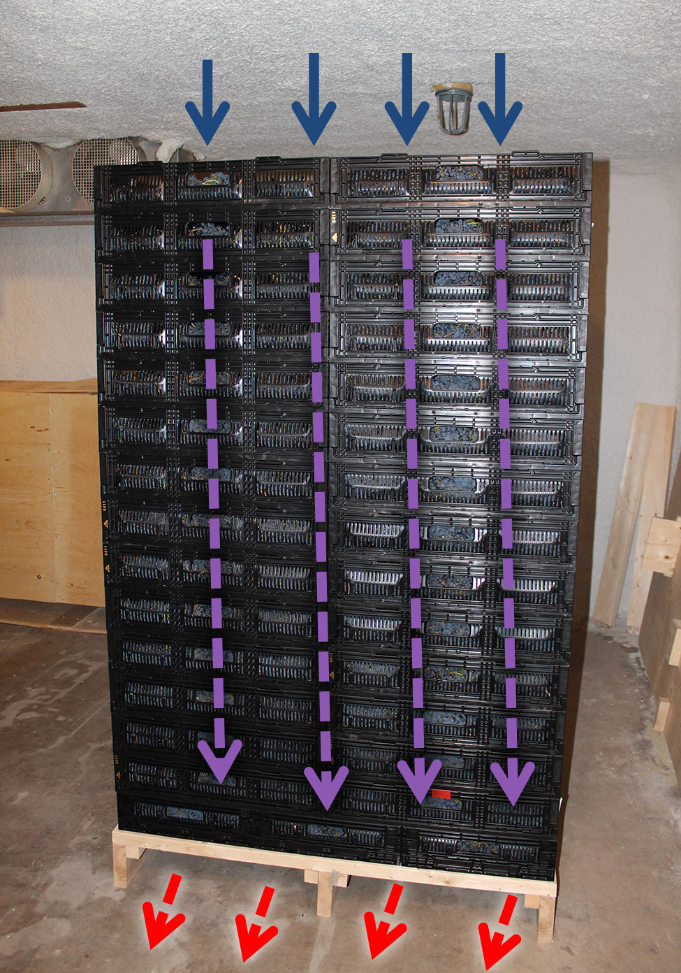
The column vertical airflow system (Figure 3) is the least common FAC system. It requires shipping containers with bottom slots such as RPCs. It is suited for small bulk produce like table grapes, mushrooms, sweet cherries or plums. Cold air can be pulled vertically up or down through the containers. This system also works for other purposes, such as slow cooling/curing of grapes for wine processed using an appassimento method, which dries and concentrates sugars and flavours.
Serpentine horizontal/vertical airflow systems (Figure 4) only work for bins with floor slots. Figure 4 shows part of a system for six columns of six bins high, tightly placed against each other. Two columns of bins are shown being cooled. Each column has an independent centrifugal fan pulling refrigerated air through that column.
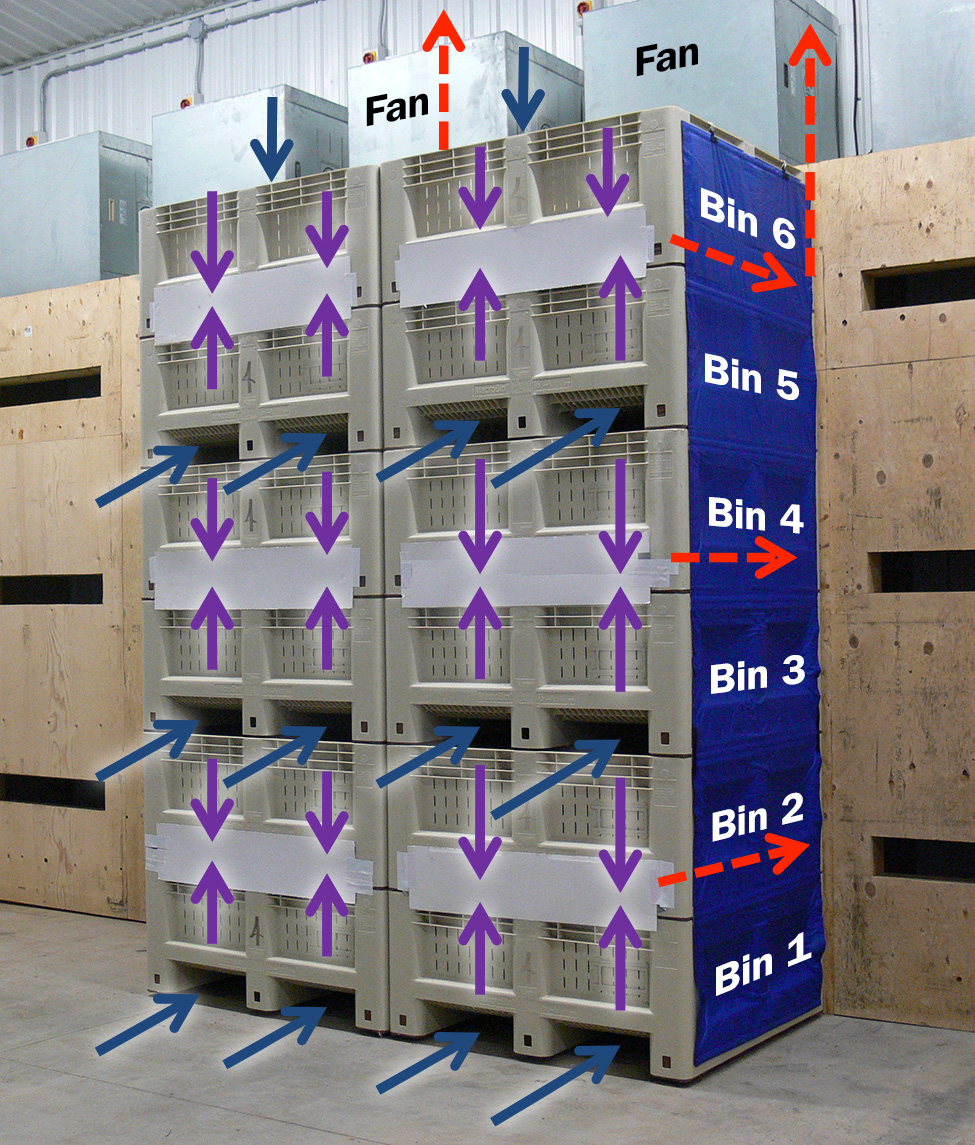
Each bin column in Figure 4 has three slot openings on a cooling wall. These align perfectly with the forklift openings of bins 2, 4 and 6. The forklift openings of these bins are covered with tarps, which “suck” tightly against the bins. As a result, refrigerated air can only enter the forklift openings of bins 1, 3, 5 and the top of bin 6.
Cold air then travels vertically “up” through slots in the bottom of bins 1, 3 and 5 and through their produce, or vertically “down” through produce in bins 2, 4 and 6 and through slots in the bottom of these bins. Finally, the air travels horizontally along the forklift openings across from the slots on the cooling wall between bins 1 and 2, 3 and 4, and 5 and 6. The name “serpentine” comes from cold air meandering in many directions. Forklift openings are not large, which can restrict airflows, so these systems are usually limited to only one to three columns of bins stacked out from the cooling wall, depending on desired airflows.
7/8 Cool time
7/8 cool time refers to the time needed to remove seven-eighths (87.5%) of the temperature difference between the initial temperature of produce and the temperature of the cooling medium (for FAC systems, the cooling medium is refrigerated air). It is measured from the time produce is first placed on the forced-air cooler. Achieving 7/8 cool time ensures most of the field heat has been removed, the respiration rate of the produce has been lowered and the produce is very close to its optimum holding temperature. In theory, produce never reaches the cooling medium temperature. However, the 7/8 cool time is intended to get produce as close as practical to the temperature of the cooling medium.
Figure 5 shows produce with an initial internal temperature of 32°C (89.6°F) being cooled with refrigerated air at 0°C (32°F). It takes 9 hr for produce to reach 4°C (39.2°F), representing an 87.5% drop. Therefore, the 7/8 cool time is 9 hr.
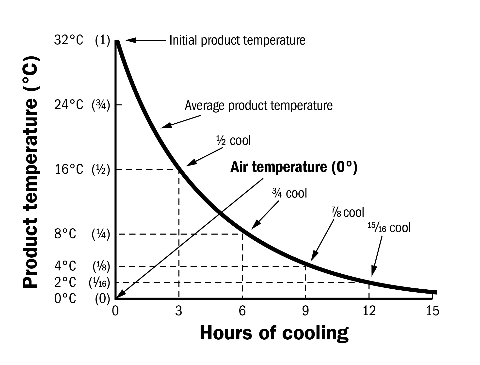
In theory, 7/8 cool time is three times the ½ cool time. Therefore, produce taking 9 hr to cool to 4°C (39.2°F) should take 3 hr to reach 16°C (60.8°F). This is seldom true, since cooling conditions and temperatures in a cold storage rarely remain constant. However, this cooling curve relationship helps predict when produce will reach a certain temperature. Table 2 lists other handy relationships.
| If you know this cooling time... | ...then multiply by following to estimate 7/8 cooling times (usually in hours) |
|---|---|
| 3⁄8 cooling time | 4.5 |
| ½ cooling time | 3 |
| ¾ cooling time | 1.5 |
Regardless of the cooling medium (air or water) or method (forced-air, room cooling, hydrocooling, etc.), produce cools quickly at first, then slowly over time (Figure 5). Several factors affect the rate of cooling in a FAC system:
- the bulk density of produce in a container (produce cools faster if packed less densely)
- the container, orientation and venting (produce cools faster if air passes uniformly by it)
- the volume to surface area ratio (produce with small ratios cools faster; for example, cherries cool faster than melons)
- the distance cooling air travels through produce (produce cools faster if the distance is shorter)
- airflow per weight (L/s/kg or CFM/lb) (produce cools faster with higher airflows if refrigeration is adequate)
Forced-air cooling in a separate room
It is best to cool produce in a dedicated FAC room before moving it out for packing and/or to longer-term storage. Otherwise, room air temperature is likely to rise after each fresh batch of warm produce is added, especially with undersized refrigeration systems. As a result, cold produce already in the room could sweat and increase slightly in temperature. However, a separate FAC room isn’t always affordable. A compromise is to create a FAC area that has much more refrigeration. This helps reduce temperature fluctuations.
Forced-air cooled produce
Most produce can be forced-air cooled. However, some produce should have shorter 7/8 cooling times (see Table 3).
| Relative perishability of crops | Commonly grown Ontario fruits and vegetables | 7/8 cool time (h) | Airflowb (L/s/kg or CFM/lb) |
|---|---|---|---|
| Very high | asparagus, broccoli, brussel sprouts, endive, green onions, kalea, leaf lettucea, parsleya, peas, sweet corn, spinacha, mushrooms | 0.75–1.5 | 2–6 |
| High | berry cropsa, cauliflower, cucumbers, head lettuce, snap beans, sweet cherries, sweet potatoes | 1–2.5 | 1.25–4 |
| Moderate | apples (early), cabbage (early), cantaloupes, celery, peaches, plums, summer squash, sweet peppers | 2–6 | 0.5–1.5 |
a Crops wilting quickly; short 7/8 cool times recommended.
b Higher airflows correspond with shorter 7/8 cool times.
Table adapted from Thompson, 2008.
Crops with very high perishability
These crops have very high respiration rates and/or wilt very rapidly at harvest temperatures, so they need short 7/8 cool times. Depending on the crop, they are often hydrocooled, iced or vacuum cooled. However, all of these crops can be successfully forced-air cooled, provided it is done promptly with high airflow rates and air that has a high relative humidity. Very high airflows of at least 2–6 L/s/kg (2–6 CFM/lb) of produce should be used, with the goal of achieving 7/8 cooling times of 0.75–1.5 hr. Monitor for signs of wilting. If the relative humidity of the cooling air is greater than 80% and the cooling period is brief, moisture loss is negligible
Crops with high perishability
These crops have high respiration rates, lose moisture at harvest temperatures and should be rapidly cooled as soon as practical after harvest. Airflow rates should be at least 1.25–4 L/s/kg (1.25–4 CFM/lb) of product and 7/8 cooling times of 1–2.5 hr. Snap beans should only be cooled to 4°C–7°C (39.2°F–44.6°F), depending on the cultivar. Otherwise, they can sustain chilling injury.
Crops with moderate perishability
Although these crops are less perishable than those already listed, it is still recommended they be rapidly cooled as soon as practical after harvest. Airflow rates should be at least 0.5–1.5 L/s/kg (0.5–1.5 CFM/lb) of produce with 7/8 cooling times of 2–6 hr.
Cantaloupes and summer squash are sensitive to chilling injury, so avoid using very cold refrigerated air. Cantaloupes should be cooled to 2°C–5°C (34°F–41°F) and summer squash to 7°C–10°C (45°F–50°F).
Components of a forced-air cooler
There are six components of a successful forced-air cooler: fan, ducting, containers, a short-circuiting prevention method, a refrigeration system and monitoring equipment.
1. Fan
The fan powers the FAC system (Figure 6), with airflow measured in litres per second (L/s) or cubic feet per minute (CFM). They can be centrifugal (squirrel-cage) or axial-flow. Many growers opt for centrifugal fans because these are often more efficient and quieter. Pulling air through containers of produce puts a lot of load on a fan, reducing its airflow. For this reason, select fans based on airflow at an operating static pressure.
Static pressure is the difference between the pressure of the airstream in the FAC plenum and the pressure of the airstream just before it enters the FAC (that is, the difference in the pressure of the airstream downstream vs. upstream of the produce). It is a measure of how much load the FAC fan must work against. Predicting static pressure is difficult because it is affected by many factors:
- air entry areas on containers
- vent alignment
- the distance air must travel through produce
- the density of produce in the containers
- ducting restrictions
For most FAC systems, static pressures range from 10–25 mm (0.4–1.0 in.) water gauge. For example, each of the 1.1 kW (1.5 hp) centrifugal fans in Figure 4 delivers 2,313 L/s (4,900 CFM) at 10 mm (3/8 in.) static pressure water gauge. So, for six bins of 225 kg (500 lbs) of produce each, the airflow rate is 1.7 L/s/kg (1.6 CFM/lb) of produce, which is a suitable airflow rate for moderate to highly perishable crops (in this case, peaches).
Doubling airflow rates per kilogram of produce speeds the cooling rate but does not cut cooling time in half. It is usually more important to increase the storage room’s refrigeration and do a better job preventing air short-circuiting than to simply increase airflow rates. For tunnel horizontal airflow systems (Figure 2), stiffeners on tarps that extend across wide tunnels may be necessary to prevent the tarp from being sucked into the tunnel if static pressures are very high.
2. Ducting
To reduce unnecessary loads on the fan, design cold air supply and warm air return spaces (Figure 1) to keep airspeeds under 5 m/s (1,000 ft/min). Make sure air does not get restricted anywhere along its path, except while travelling through the produce. The relationship is:
Q = A × V or A = Q ÷ V, where:
- Q is airflow rate, measured in L/s (CFM)
- A is cross-sectional area perpendicular to airflow, measured in m2 (ft2)
- V is air velocity, measured in m/s (ft/min)
For example, to determine the cross-section needed if the airflow rate is 5,000 L/s (5 m3/s) and airspeed is 5 m/s:
A = Q ÷ V
= 5 m3/s ÷ 5 m/s
= 1 m2 of cross-section
Therefore, provide at least 1 m2 of cross-section for every 5,000 L/s (or 5 m3/s) of airflow (1 ft2/1,000 CFM) in all cold air supply spaces and warm air return spaces. These spaces differ depending on the FAC system and airflows.
3. Containers
The container design and venting system can make or break a FAC system. Ideal containers have straight walls (no taper) so containers fit tightly together. They also have vents that:
- occupy 25% of the area perpendicular to the airflow direction
footnote 4 - are evenly distributed across the airflow path
- line up along the cooling path
- are designed as long slots rather than round holes so produce won’t plug them
- are unrestricted by liners, trays or pack materials
4. Short-circuiting prevention method
Preventing short-circuiting of cooling air is a critical but often overlooked feature of a good FAC system. Air takes the path of least resistance, so even small cracks must be plugged. Ten per cent of air in a well-designed and well-operated system may short-circuit, while more than 30% of air may short-circuit in poorly designed and poorly operated ones
Pulling air with a fan is more efficient than blowing it. Pulling air sucks sheets or tarps against the containers, preventing cold air from leaking out and short-circuiting to the fan.
There are many locations for air to short-circuit, including:
- forklift openings
- shipping containers that do not fit tightly on the sides or top or that do not fit the pallet dimensions
- areas where pallets/bins fit against the cooling wall in tunnel or serpentine FAC systems
- areas between containers on top of pallets and loose-fitting tarps in tunnel FAC systems
A $50 static pressure gauge from farm ventilation suppliers measures the static pressure load a fan must work against between cold air supply spaces and warm air return spaces. As short-circuit holes are plugged, static pressures rise, indicating fans are working harder since more air is being pulled through the produce, which offers more resistance. Use cellophane or light ribbons to check for the presence of gaps or holes, as they will get sucked into even small ones.
Common methods of preventing short-circuiting are:
- installing foam or door seals between pallets/bins and cooling walls
- ensuring shipping containers fill pallets fully so there are no gaps between pallets
- ensuring tarps fit snugly against bins or containers
- installing cushioned floor bumpers that pallets butt against to prevent short-circuiting through forklift openings
5. Refrigeration system
You can never have too much refrigeration in a cold storage. Because the produce immediately begins to cool once FAC begins, the initial slope of the cooling curve in Figure 5 is very steep. The amount of refrigeration needed at the start of cooling can be very large. The formula for required refrigeration in kJ/h (Btu/h) is:
kJ/h (Btu/h) = 2.08 × (A-B) × C × D ÷ E, where:
- 08 = Natural logarithm of 1/8
- A = Temperature of the produce, measured in °C (°F)
- B = Temperature of the cooling medium (air), measured in °C (°F)
- C = Weight of the produce being cooled, measured in kg (lbs)
- D = Specific heat of the produce: 3.77 kJ/kg/°C (0.9 Btu/lb/°F)
- E = 7/8 cooling time, measured in hr
Adapted from the momentary cooling rate formula
Example:
The operation shown in Figure 4 has a serpentine horizontal/vertical airflow system with 36 bins. Each bin holds 225 kg (500 lbs) of peaches, so there are a total of 225 kg × 36 = 8,100 kg (18,000 lbs) when the system is fully loaded. What cooling capacity is required to cool the peaches from 28°C (82°F) to 3.5°C (38°F) in 3.5 hr, using cooling air that is 0°C (32°F)? This represents a 7/8 cooling time of 3.5 hr.
The worst-case scenario is if all six columns of bins are moved into the cooler at the same time, containing produce that is 28°C. From the formula above, the momentary refrigeration at the beginning of cooling in this worst-case scenario would be:
2.08 × (28°C − 0°C) × 8,100 kg × 3.77 kJ/kg/°C ÷ 3.5 hr
= 598,136 kJ/hr, or 141.1 kJ/s, or 141.1 kW of refrigeration
(2.08 × (82°F − 32°F) × 18,000 lbs × 0.9 Btu/lb/°F ÷ 3.5 hr = 481,371 Btu/hr of refrigeration)
Using an Imperial system industry term, a ton of refrigeration equals 3.5 kW (12,000 Btu/hr). Therefore, 141.1 kW ÷ 3.5 kW/ton equals approximately 40 tons refrigeration. It is unlikely, and indeed undesirable, to load the entire FAC up with hot produce at the same time, so installing this much refrigeration would be unnecessary and costly. If this system was uniformly loaded over time, there would be some fruit that was partially cooled and other fruit that was almost completely cooled, such that only 50% as much refrigeration was actually necessary. However, uniform loading is difficult to achieve, and bottlenecks occur in the real world. Instead, as a rough guide, design the facility for 2/3 the momentary refrigeration rate at the beginning of cooling:
141.5 kW × 2/3 = 94 kW, or approximately 27 tons of refrigeration
(481,371 Btu/hr × 2/3 = 320,247 Btu/hr, or approximately 27 tons of refrigeration)
At this lesser refrigeration level, the air temperature of the room might rise slightly when new produce begins cooling, but it will gradually recover. Of course, this is only the amount of refrigeration over and above the amount required to address heat coming from elsewhere in the storage area, such as through walls, ceiling and opening and closing doors, etc.
Do not install ducts to take warmed air from the FAC fan directly to the refrigeration system’s evaporator coils or to take cold air from the evaporator coils directly to produce being cooled. In most cases, evaporator coils and fans were not designed for this direct connection. Warmed air should be directed to within 3–5 m (10–16 ft) of evaporator coils. Cold air from the evaporator coils should also be directed at least 3–5 m (10–16 ft) away from the FAC unit. Since evaporator coils must cool air below the desired room air temperature, air directly off the coils might cause cold injury to produce. The storage refrigeration system should be designed to provide a high relative humidity (at least 80%, and preferably over 90%) to help prevent wilting produce during FAC.
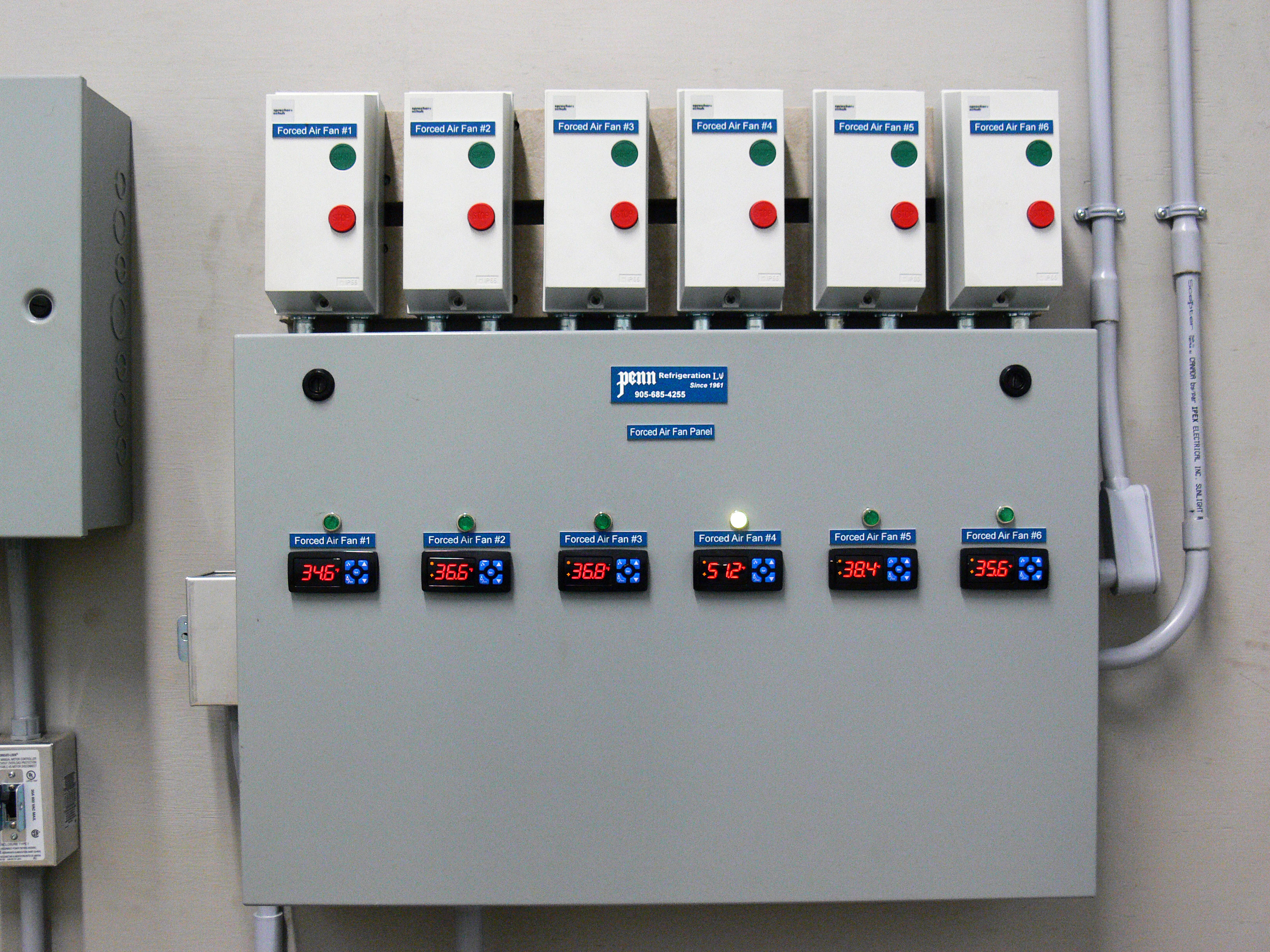
6. Monitoring equipment
Proper monitoring is critical to the success of a FAC system. It is important to know the following:
- the temperatures of the incoming cold air and outgoing warm air in the FAC system
- the relative humidity in the storage
- the elapsed time produce has been on the FAC system
- the static pressure fans must work against during FAC
Periodically record internal temperatures of several pieces of produce, especially if you have little experience with FAC systems. This becomes less necessary with experience. Check temperatures by probing the produce centre with good measuring equipment that give an instantaneous digital readout. Make sure you discard any produce you have probed! “Hot” produce temperatures in the field may not be the same as surrounding air temperatures in the field. Likewise, “cold” produce temperatures in cold storage may not be the same as surrounding air temperatures in cold storage. Large produce like cantaloupe takes longer to warm up or cool down than small produce like plums.
It is time-consuming to monitor produce temperature but easy to monitor temperatures of cold air entering and warm air exiting the FAC system (Figure 6). Warm air will be about mid-way between the temperature of cooling air entering the FAC system and current produce temperature. Produce that is closest to the incoming cold air cools more quickly than produce downstream, because the air warms as it passes over the produce. Over time, however, downstream produce will gradually catch up and there will be little difference in temperature throughout the stack, especially with high airflow rates. Decisions can be made about when to remove produce from the FAC to prevent running equipment longer than needed, save on electricity, prevent needless adding of heat from motors into the cold storage and prevent the produce from drying out.
Cost-benefit considerations
Removing field heat rapidly and uniformly after harvest is critical for many crops to help maintain shelf life — but at what cost? Every situation is different, but as an example, suppose the system described in the “Refrigeration” section was analyzed with these assumptions:
- A grower already needs more refrigeration because his/her produce is not cooling rapidly enough. No extra cold storage building is necessary.
- A serpentine horizontal/vertical airflow system is added to the existing cold storage at $150,000 fixed cost that includes:
- 27 tons of additional refrigeration
- a custom-made strong plywood plenum with bumper padding around the FAC slot openings
- high-capacity forced-air cooling fans
- associated wiring, sensors, timers and controls
- 36 bins (8,100 kg) of peaches are cooled per batch, with 2.5 batches, on average, every day, over an 8-week (56-day) season. FAC is used 50 of 56 days. Therefore, 8,100 kg/batch × 2.5 batch/day × 50 days ≈ 1,000,000 kg
- Extra annual operating costs for hydro, maintenance, insurance, etc. over previous expenses = $5,000/year
- Fixed cost of $150,000 FAC system amortized over 15 years, at 5.5%, recognizing that the system could last 25–30 years = $15,000/year
- Total annual costs: $15,000 + $5,000 = $20,000
- Total cost/kg/year over the 15-year life of the FAC system
= $20,000/1,000,000 kg
= $0.02/kg/year (0.9¢/lb/year)
There are at least three ways to look at the question of whether the benefits of forced-air cooling will offset costs:
- Will improved quality lead to increased demand for your produce and a higher selling price? A 3-L basket of peaches weighs 2 kg, so you’d have to receive at least 5¢ more per basket of fruit to pay for the FAC (2.5¢/kg × 2kg/basket). If this was the case, your produce would need to be distinguishable from your competitors’ produce. Increased demand for your produce can also lead to less produce being simply left in the field because of a lack of market.
- If you don’t use a FAC system, will the resulting poor-quality lead to decreased demand for your produce and ultimately fewer sales? Consumers continue to demand high-quality produce, and if they cannot find that quality from you, they’ll go elsewhere. The quality bar continues to rise, and ways to maintain that quality can quickly become the new norm.
- How does your current quality stack up against your competition, both inside and outside Ontario? If the market demands produce with a shelf life of X days, does your produce measure up? The average wholesale price for Ontario peaches from 2008–2012 was $1.35/ kg. So, if you stored produce for X days in your cold storage, you’d need at least 1.85% less spoilage to pay for FAC (2.5¢/kg ÷ $1.35/kg × 100%). That is one out of every 5 peaches. If a 3-L basket holds 12 peaches, this is about one peach out of every four baskets. If you, or your buyers, currently discard this much produce because of poor shelf life, FAC may be part of the solution.
Conclusions
Cold storage removes heat from produce through a combination of conduction and convection. Conduction is the transfer of heat between objects in physical contact with each other, while convection is the transfer of heat between an object and a fluid such as cold air. Convection is more efficient and quicker. However, convection cannot occur in a cold storage unless we “force” cold air to move around the produce. Forced-air cooling is the most flexible and efficient method for removing field heat quickly, but it can only be accomplished by careful design and operation.
This fact sheet was written by Hugh Fraser, P. Eng. (retired), horticultural crop protection & postharvest specialist, OMAFRA. It was reviewed by Brian Baert, Hespro Group, Stevensville; Dennis Bering, Penn Refrigeration, St. Catharines; Dr. Jennifer DeEll, fresh market quality program lead, OMAFRA; Dr. Bernard Goyette, P. Eng., post-harvest research scientist, Vineland Research and Innovation Centre, Vineland.
Footnotes
- footnote[1] Back to paragraph Kader, A.A. 2002. Postharvest Technology of Horticultural Crops, Publication 3311, Third Edition, University of California, 4:39-42.
- footnote[2] Back to paragraph Thompson, J.F., F.G. Mitchell, T.R. Rumsey, R.F. Kasmire, C.H. Crisosto. 2008. Commercial Cooling of Fruits, Vegetables and Flowers, Publication 21567, Revised Edition, University of California, 1:2–3, 2:14, 5:33, 7:38.
- footnote[3] Back to paragraph Thompson, J.F., F.G. Mitchell, T.R. Rumsey, R.F. Kasmire, C.H. Crisosto. 2008. Commercial Cooling of Fruits, Vegetables and Flowers, Publication 21567, Revised Edition, University of California, 1:2–3, 2:14, 5:33, 7:38.
- footnote[4] Back to paragraph Vigneault, C., B. Goyette. 2002. Design of plastic container openings to optimize forced-air precooling of fruits and vegetables. Applied Engineering in Agriculture, 18(1):73–6.
- footnote[5] Back to paragraph Thompson, J.F., F.G. Mitchell, T.R. Rumsey, R.F. Kasmire, C.H. Crisosto. 2008. Commercial Cooling of Fruits, Vegetables and Flowers, Publication 21567, Revised Edition, University of California, 1:2–3, 2:14, 5:33, 7:38.
- footnote[6] Back to paragraph Thompson, J.F., F.G. Mitchell, T.R. Rumsey, R.F. Kasmire, C.H. Crisosto. 2008. Commercial Cooling of Fruits, Vegetables and Flowers, Publication 21567, Revised Edition, University of California, 1:2–3, 2:14, 5:33, 7:38.