Rooftop solar installations on rural buildings
Learn what questions to ask when considering a rooftop solar installation. This technical information is for rural landowners in Ontario.
ISSN 1198-712X, Published January 2023
Introduction
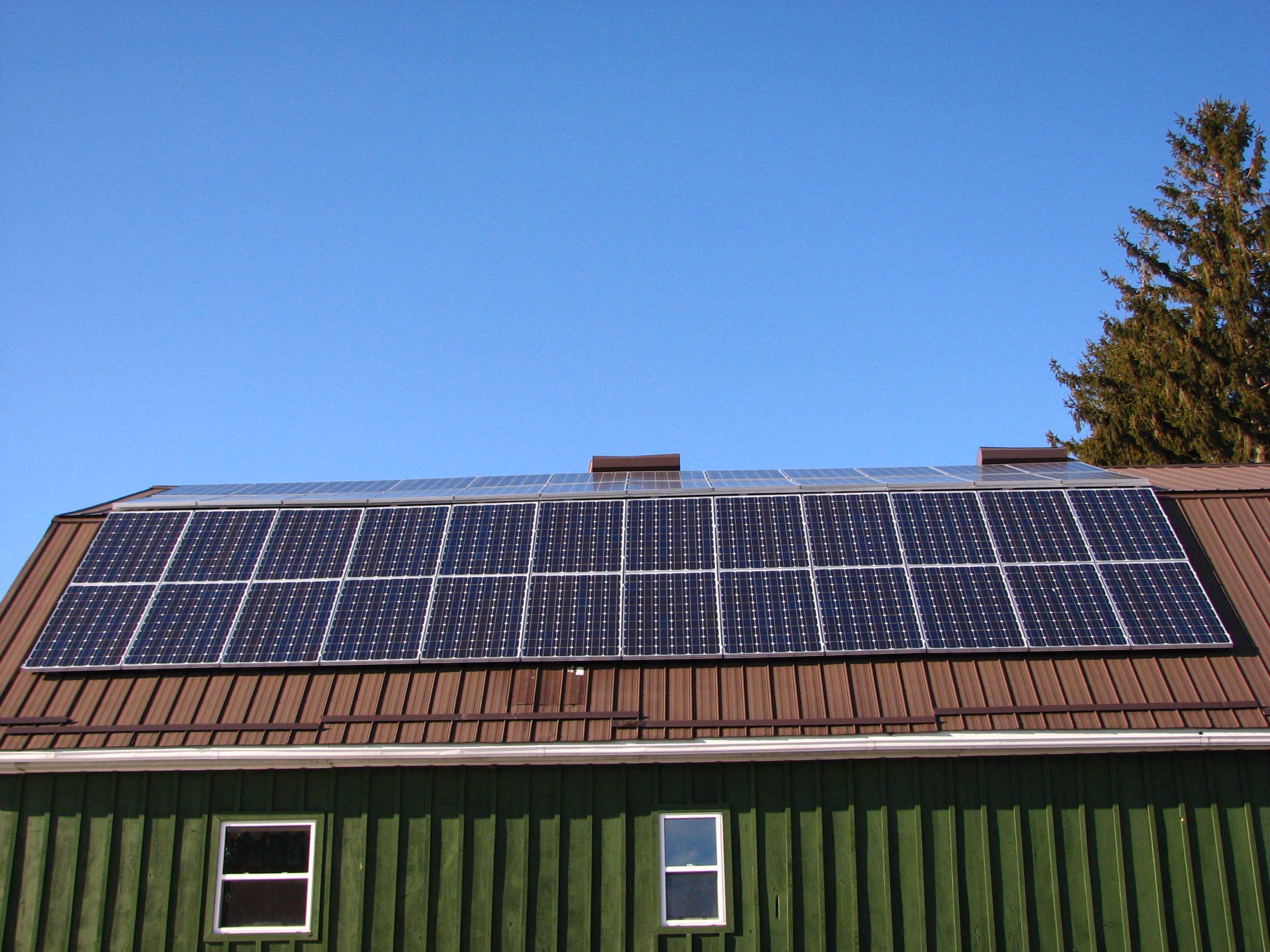
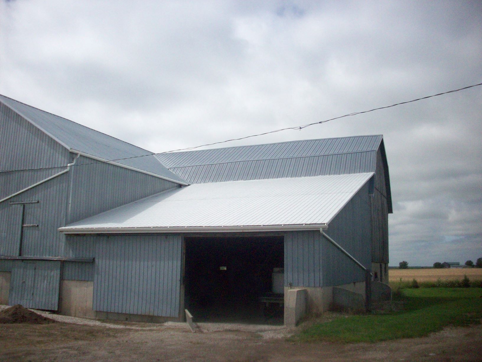
The rooftop of a farm building can be an ideal location for a solar installation (Figure 1). Rooftops have large surface areas with few obstructions, and the landowner typically has control over objects that might shade the solar modules over the life of the installation. The challenge is that most existing farm structures weren’t designed to carry rooftop solar installations. As a result, there are a number of questions to ask when considering a rooftop solar installation. This fact sheet looks at these questions and things to consider.
Design factors used in agricultural buildings
The National Farm Building Code of Canada, 1995, outlines some of the specific structural requirements for farm buildings of low human occupancy (a farm building with an occupant load of not more than one person per 40 m2 of floor area during normal use). When a farm building of low human occupancy meets the specific conditions, the engineer may decide to reduce the total roof design load in one of two ways.
Wind exposure factor
In exposed conditions, where the rooftop is likely to remain “windswept” over the service life of the structure, the engineer may include a reduction factor in the total roof design load calculation. If this factor was used in the original design of the structure but no longer applies, due to the addition of a nearby obstruction (silo, lean-to, tree), the structure may require reinforcing to meet current code requirements.
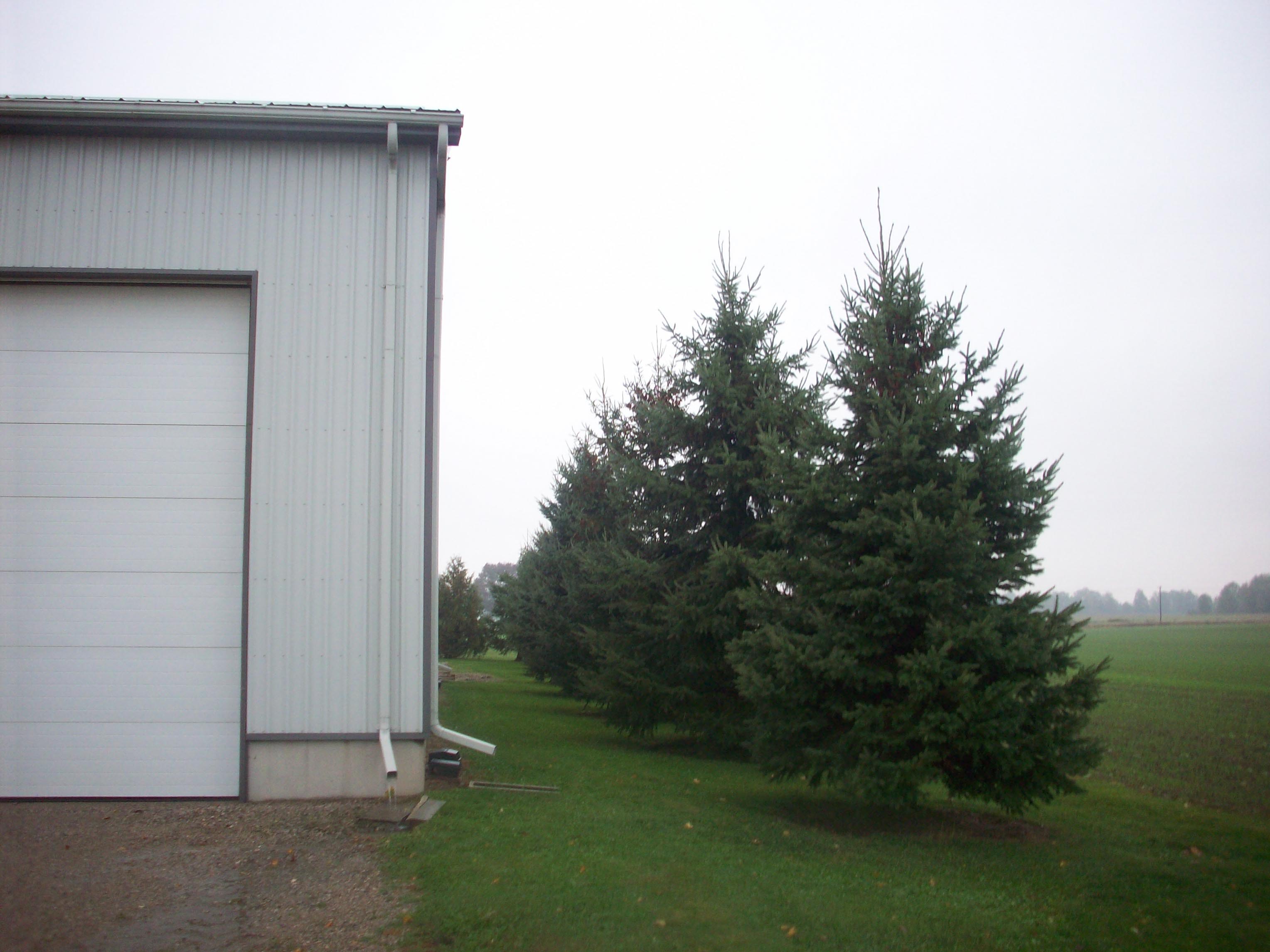
Figure 2 shows a building that is windswept today but may not be windswept after the trees grow in height. The wind exposure factor was used widely in previous years but is not as commonly used now. The factor takes into account the height of the obstruction in relation to the height of the rooftop and how far it is located from the roof. It is difficult for an engineer to be confident that the structure will remain windswept for the service life of the structure.
Slippery roof design factor
The slippery roof design factor is used with unobstructed smooth and slippery surfaces such as sheet metal (commonly found on farm buildings) or glass to reduce the total roof design load, where the slope of the roof allows. The slippery roof design factor is also known as the slope factor.
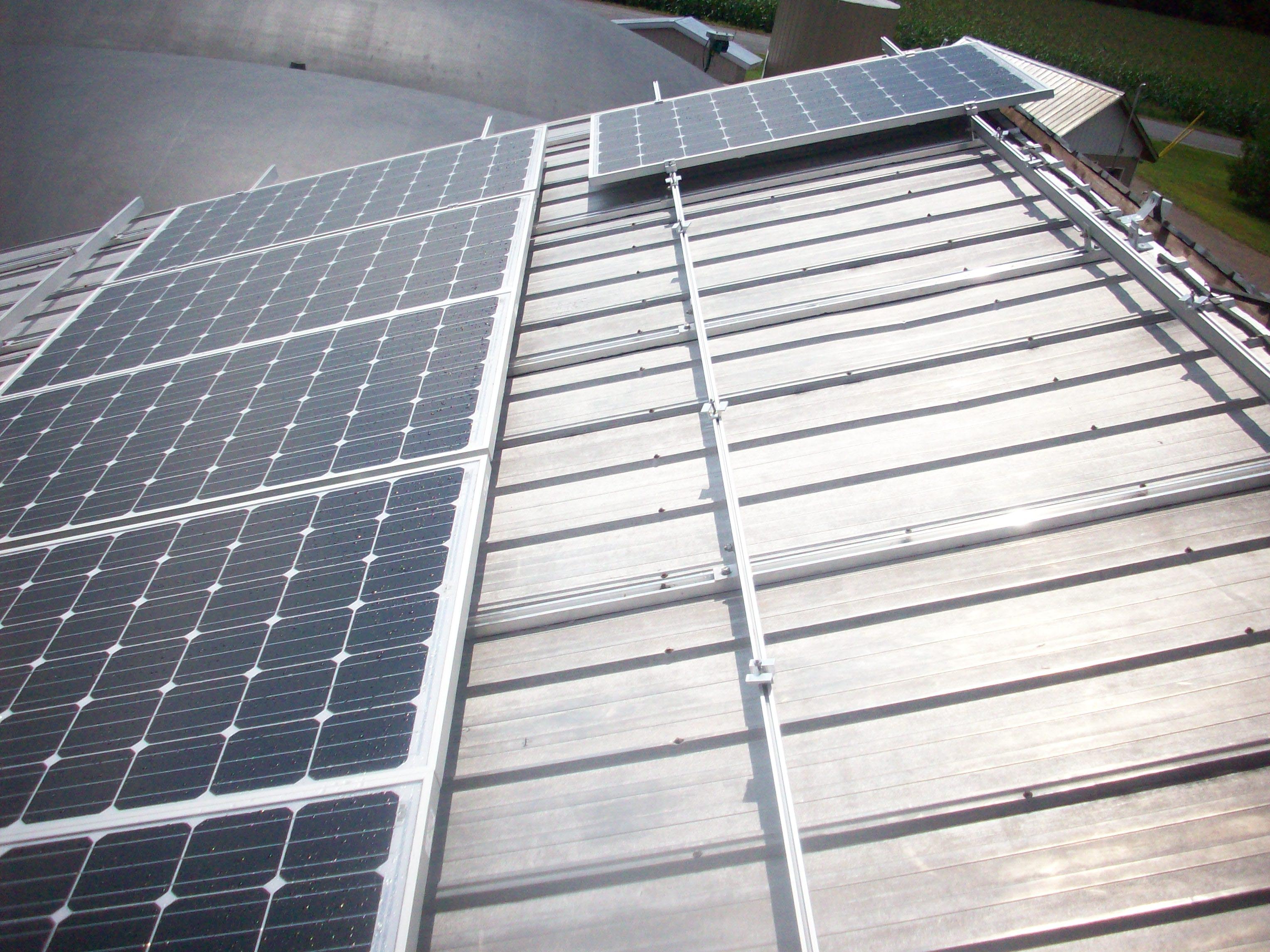
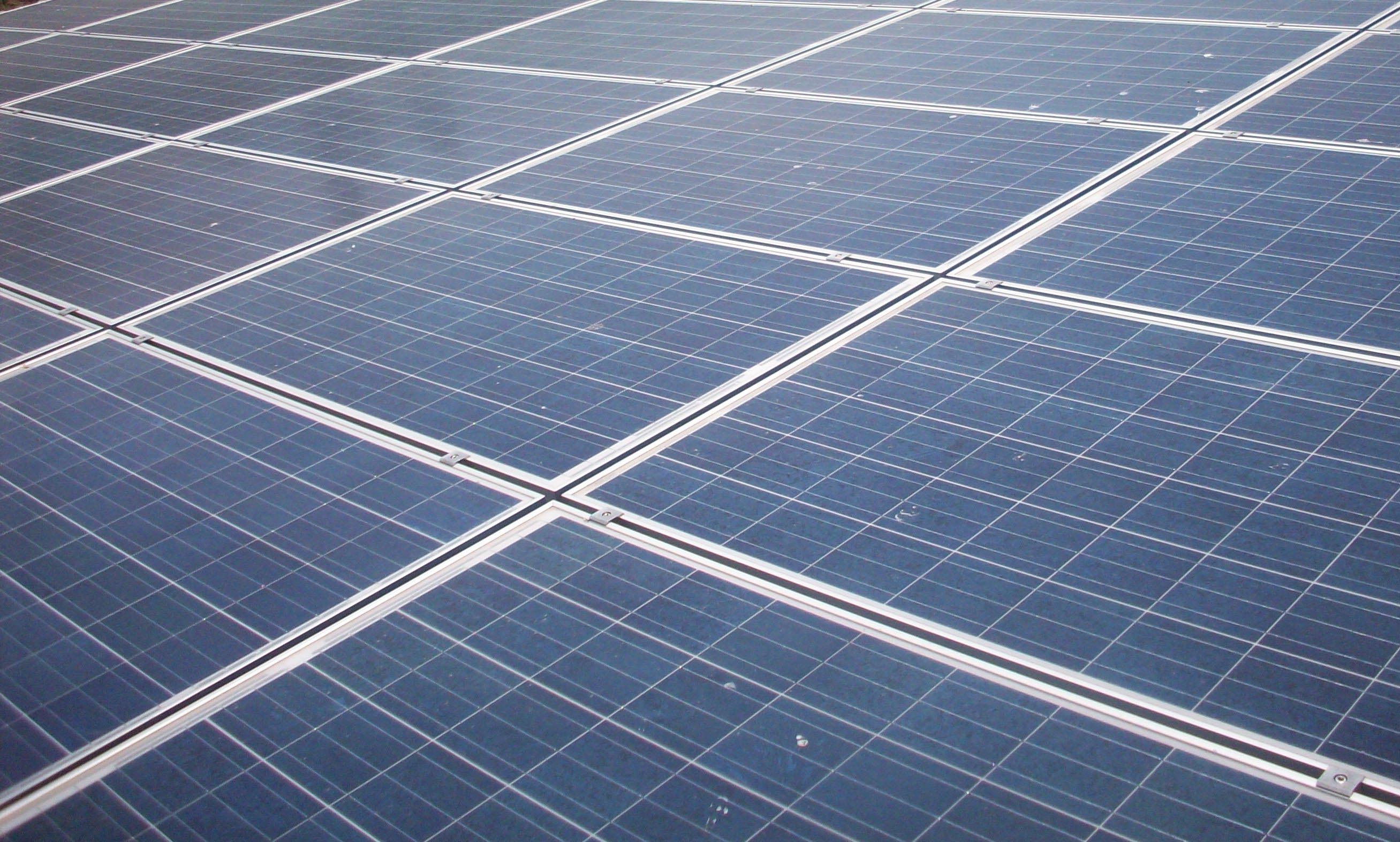
Crystalline silicon (monocrystalline or polycrystalline) solar modules have glass surfaces and are applied to the roof in a number of ways. Two methods are shown in Figures 3 and 4. In both cases, it is uncertain if snow will slide completely off the roof as easily as it would have before the installation. Figure 3 shows an installation with rows for maintenance access and ventilation. Figure 4 shows an installation where the modules are installed tightly together, with a gap between rows of approximately 19 mm. Both installations use crystalline silicon modules.
The engineer determines if snow would be free to slide completely off the roof and if the slippery roof design factor can be applied when completing the associated total roof load calculations. Ice/snow guards, eavestroughs and the condition of the roof cladding are also considered. Figure 5 shows a rooftop with eavestroughs and valleys that requires special consideration, since snow is not free to slide completely off any of the roof surfaces.
Layout of modules and reinforcing requirements
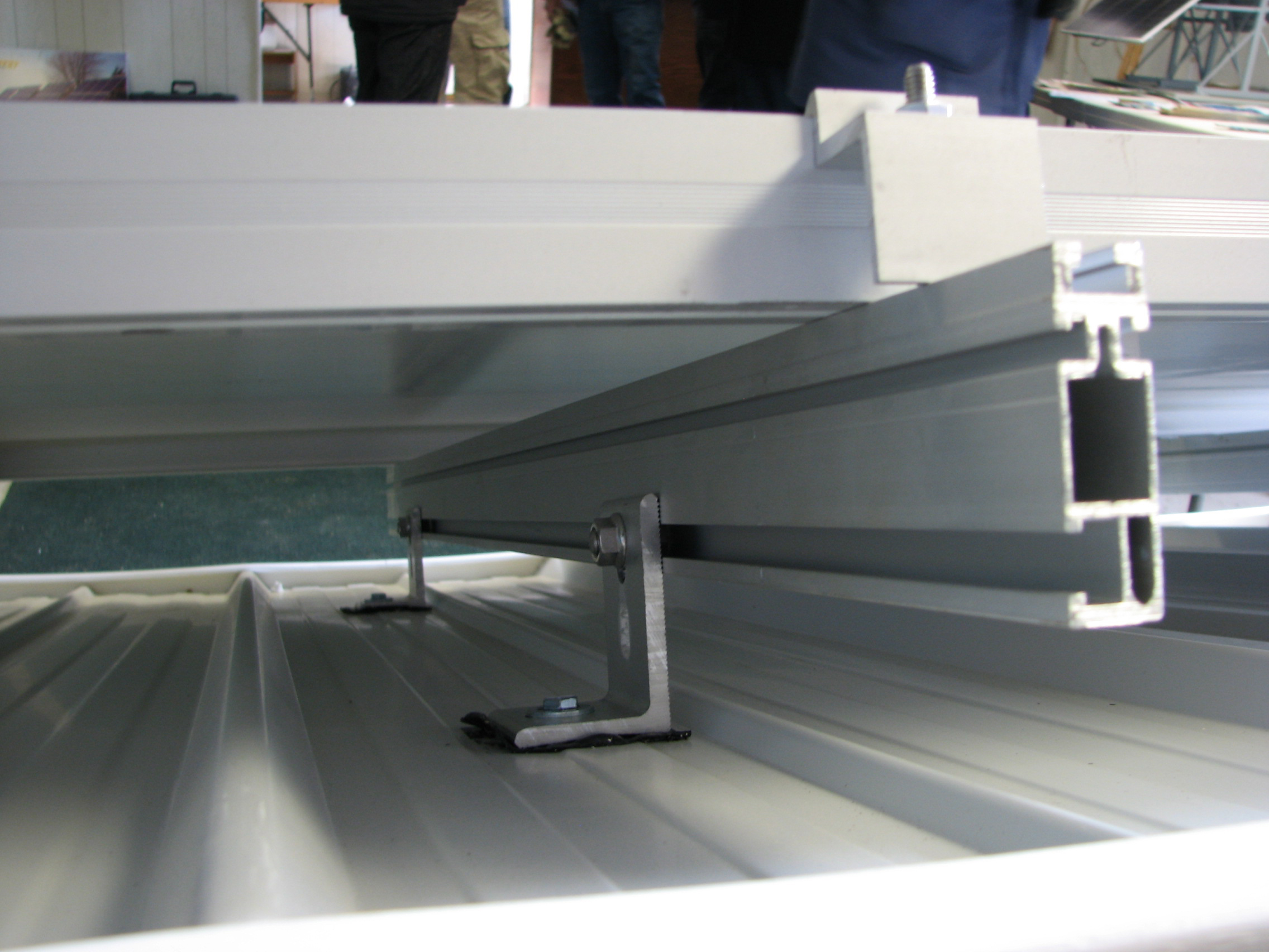
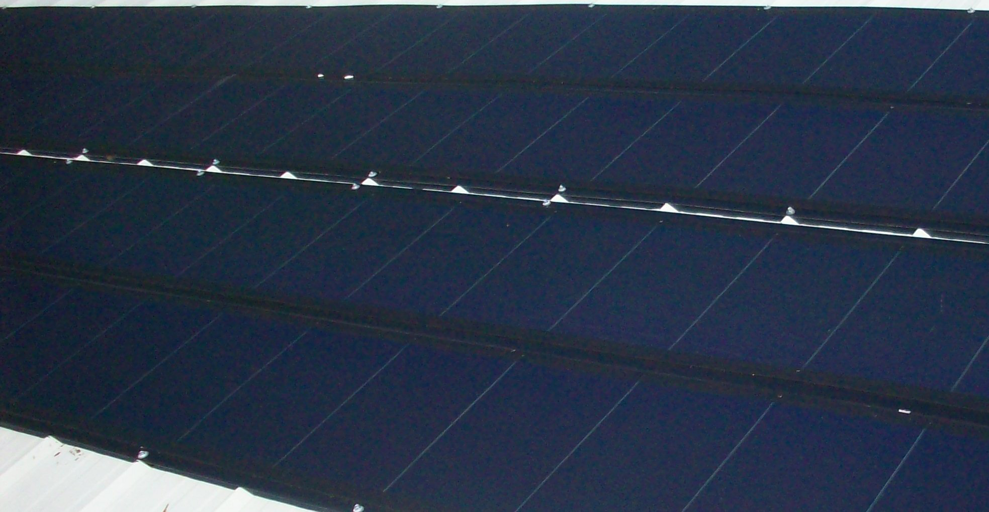
Crystalline silicon (c-Si) solar modules are often installed on aluminum rails attached to the roof at specified spacings. As a result, the weight of the modules and anything on top of them (for example, snow) is only transferred to the rest of the structure at certain points. Figure 6 shows the underside of a rooftop solar installation where the load is transferred at various points below the solar installation. Many farm structures are built with wood roof trusses. Engineers review these structures to understand if a particular installation can be modeled as a uniformly distributed load or as point loads that the trusses need to support.
Engineer’s site visit
To calculate the total roof design load, the engineer must determine if the rooftop is windswept and if it will be slippery after the modules are installed. This information is best obtained by direct observation and by discussing the design layout with the owner.
Although the roof trusses are a critical structural component, the engineer must review the entire structure. Other components to examine include the wall studs, lintels, posts, beams, footings, bracing system and foundations. Engineers ensure these components have adequate strength to support the load and that they have been properly maintained.
Common deficiencies found in Ontario farm buildings
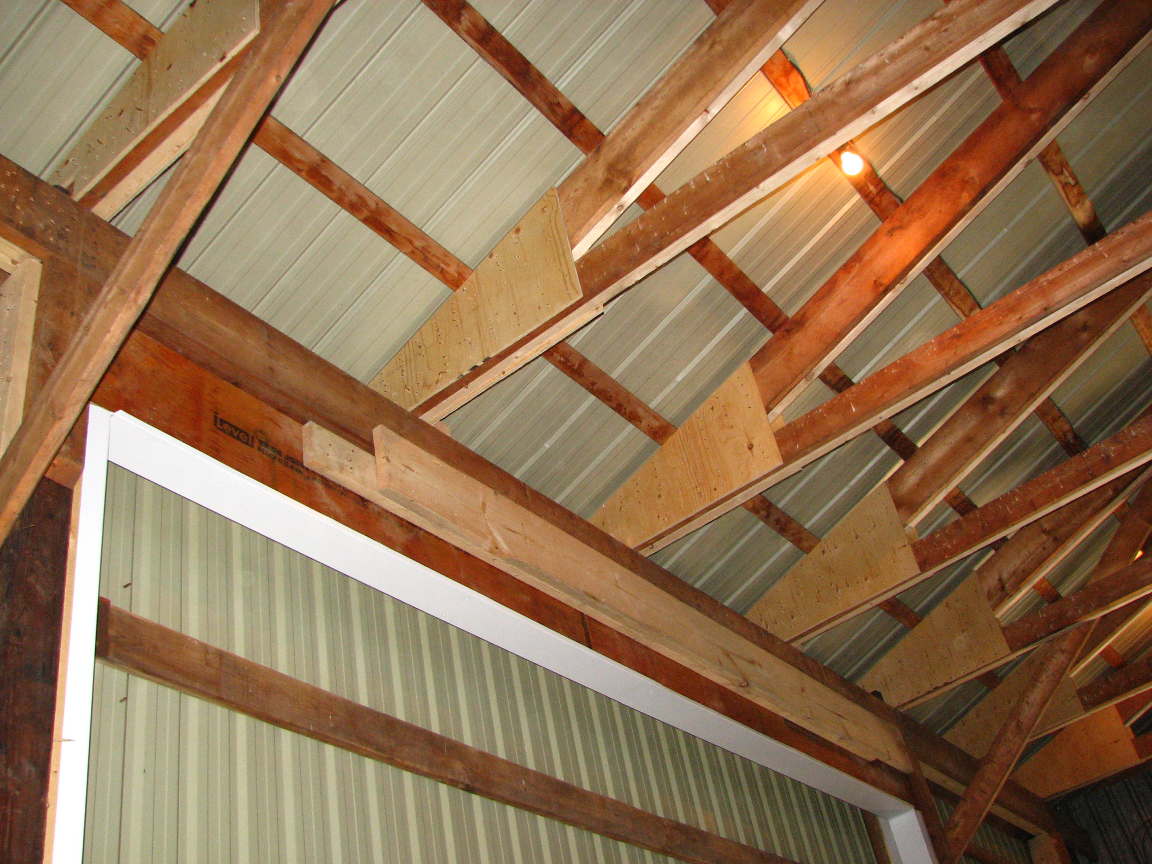
There are a variety of deficiencies to look for and they vary, depending upon the use of the structure. The environment in a livestock building is wet and corrosive, due to the livestock. Any air entering the attic space from the livestock environment will likely corrode the truss (gusset) plates. Figure 7 shows the truss plate in a 7-year-old barn. The barn has a ventilation system, but the system did not prevent the moist air from entering the attic space. As a result, all of the peak truss plates are corroding.
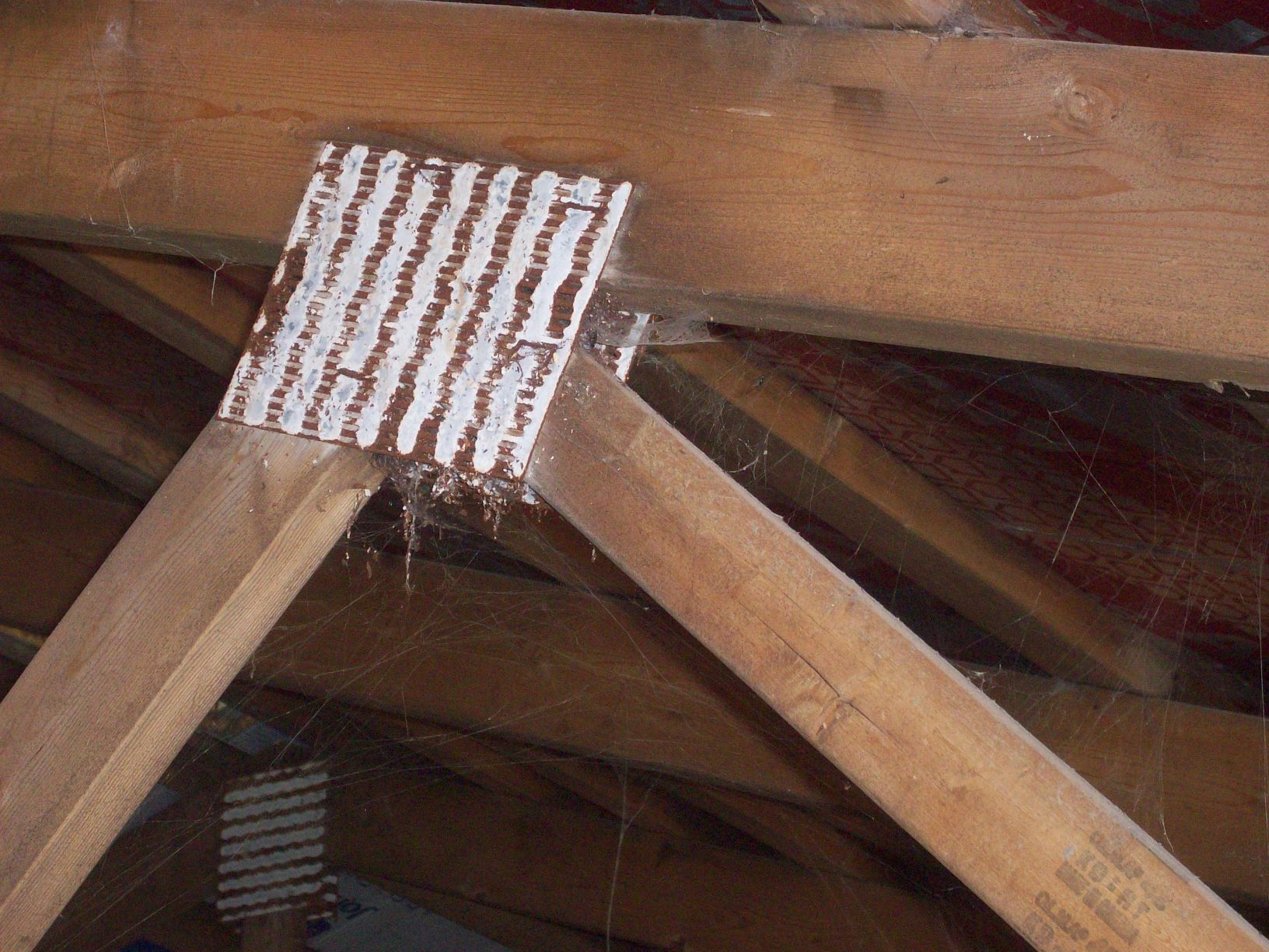
Take into account corroding truss plates in farm buildings when considering rooftop solar installations. Find more information on this topic in OMAFRA fact sheet, Corrosion of roof truss connector plates in farm buildings.
Another common deficiency is the lack of adequate bracing. In some cases, bracing was never installed, is insufficient or has been removed. There are a variety of different bracing techniques that depend on factors such as the size and shape of the building. For example, a review will confirm if the permanent lateral bracing was applied to the required compression webs in a wood truss building. This bracing helps prevent buckling and is anchored to prevent lateral movement (the “domino” effect). This anchoring is often achieved through the use of diagonal bracing.
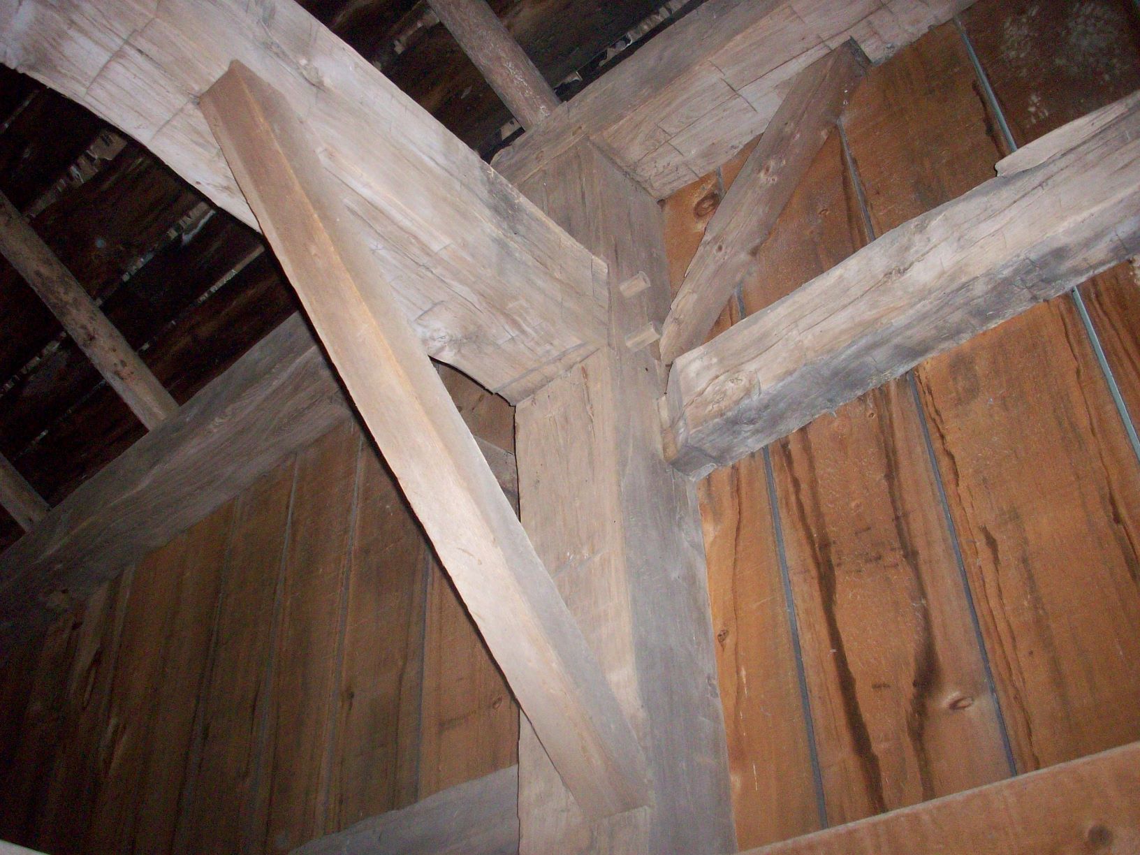
Older buildings present unique challenges. It can be difficult to determine the grade of lumber that was used to build the barn. This information is helpful in completing the review. Some older barns have complex connections (Figure 8) that require hand calculations to determine the design load. These connections may have been damaged or altered over the years.
Final engineering inspection
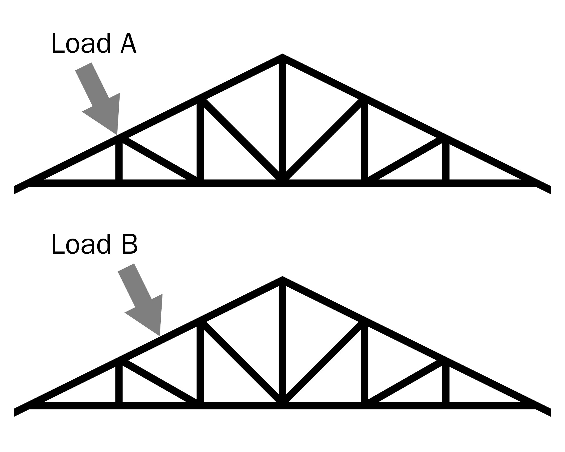
The engineer will complete the roof load design calculation, based on certain assumptions. To confirm that these assumptions were accurate, the engineer will have to inspect the finished product. For example, the placement of the solar modules along the length of the truss is important. Figure 9 shows a truss that has the point load applied in two different spots. If the point load was designed to occur at location A, the top chord of the truss is well supported at the node by the webs beneath. If that point load moves along the length of the top chord to location B, the top chord will experience more bending force, which could lead to additional reinforcing requirements.
It is also important that the roof has been reinforced correctly. Things to review in the finished product include the size of any additional truss plates, proper nail patterns and the size and location of additional support pieces. Figure 10 shows an example where significant bottom chord and truss plate reinforcing was required.
Engineering, reinforcing materials and labour costs
In 2011, OMAFRA participated in a study examining the engineering, reinforcing, materials and labour costs associated with solar installations on farm buildings. Many different types of rural buildings were examined (dairy, poultry, hog, storage), and the ages of the buildings varied significantly.
The results of the study indicated that the costs for engineering, materials and labour to make the rural buildings studied “solar ready” varies substantially with the age of the building and type of solar technology. In this case, “solar ready” includes a site visit, full building engineering review, and reinforcing labour and material. Table 1 summarizes the results for crystalline silicon modules installed on each rooftop.
The buildings in Table 1 didn’t require modifications to the footings or other major structural components. Changes to the footings of a structure would significantly increase the project cost.
| Site | description | Example | Meets current code requirements | Energy produced (kW) | Total cost ($) | Total ($/kW) |
|---|---|---|---|---|---|---|
| 1 | 2007 152-m long poultry operation | 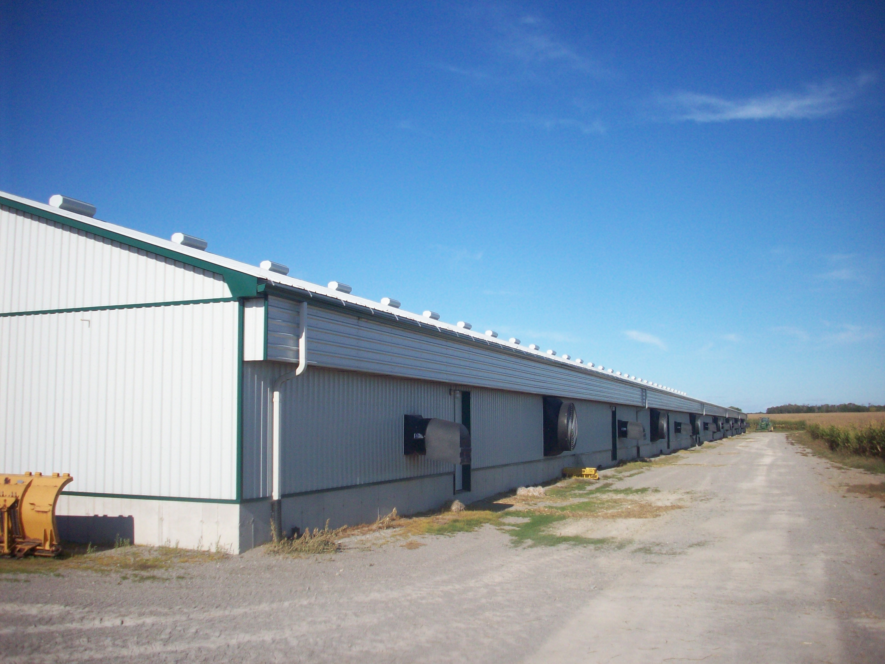 | Y | 232.2 | 20,254.00 | 87 |
| 2 | circa-1900 bank barn, timbers require grading | 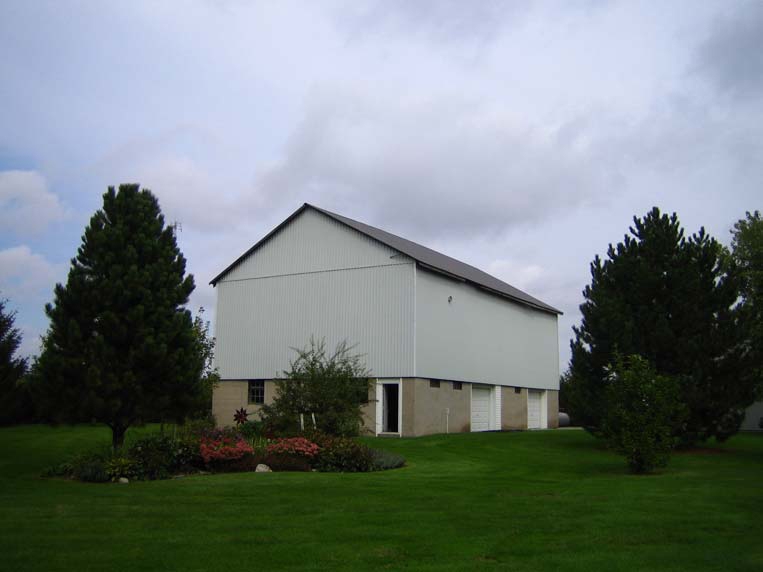 | N | 18.92 | 8,083.75 | 427 |
| 3 | 1973 hand-built hay storage, gambrel roof | 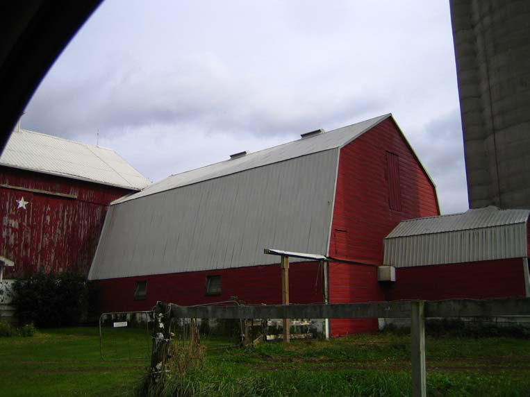 | N | 18.275 | 11,200.00 | 613 |
| 4 | 2002 single-storey storage shed with drawings | 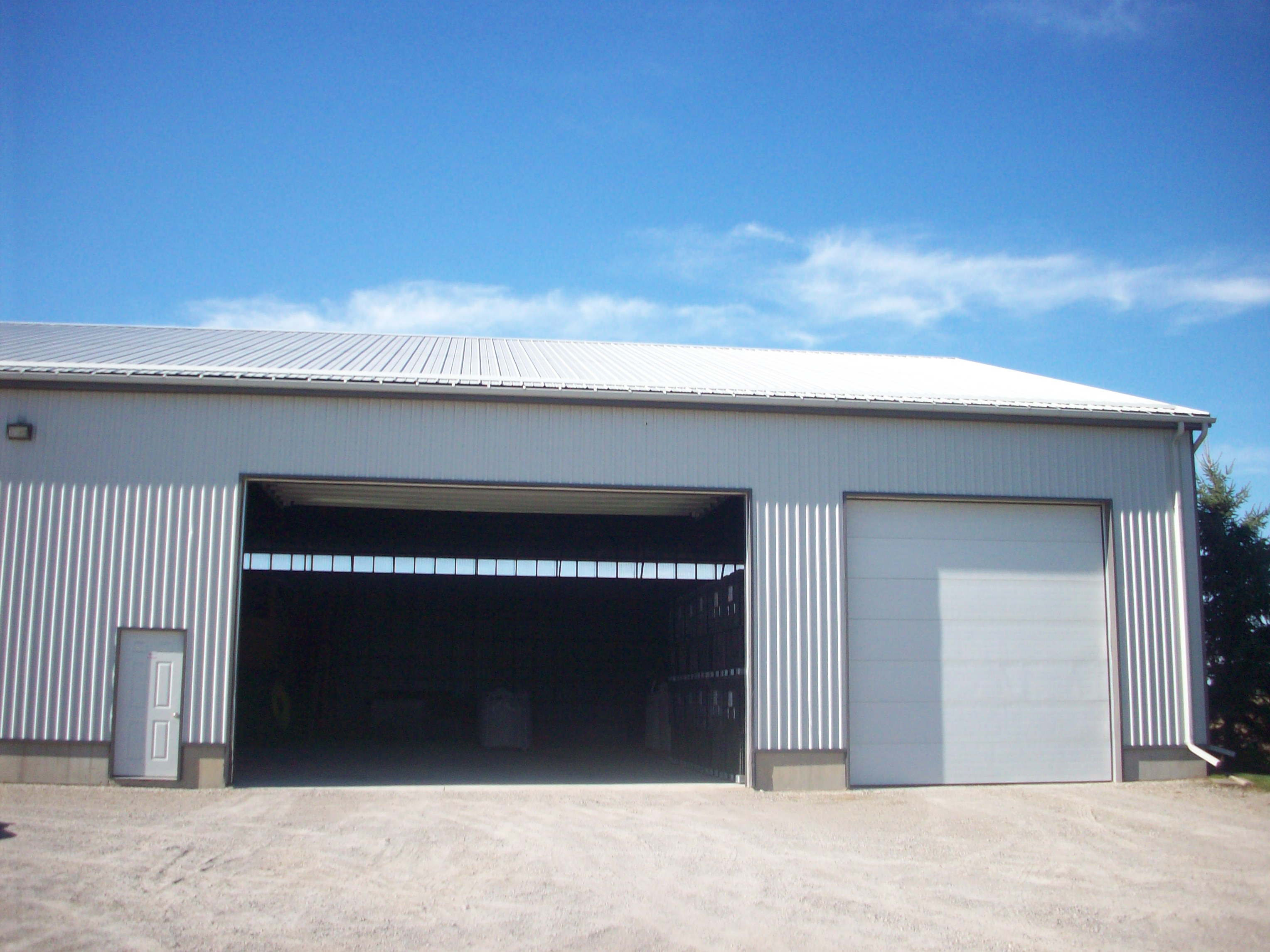 | N | 50.3 | 8,552.00 | 170 |
| 5 | 1994 single-storey dairy barn | 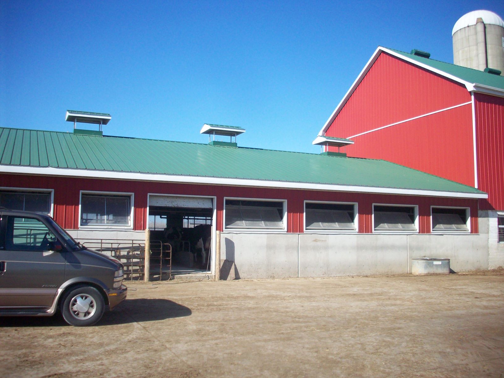 | N (truss lateral bracing only) | 29.025 | 7,688.81 | 265 |
| 6 | 2006 single-storey dairy barn. Mono-slope roof trusses with interior steel support beams. | 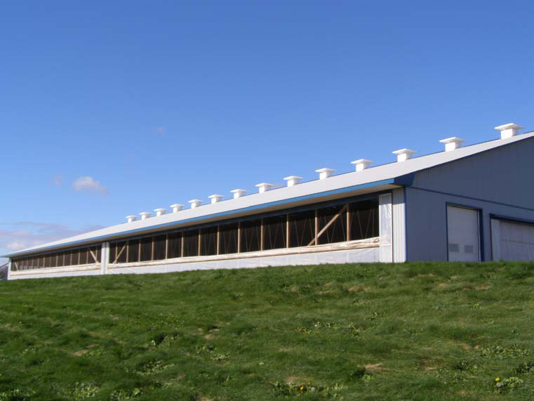 | Y | 215 | Only three rows of solar modules could be applied. | Only three rows of solar modules could be applied. |
| 7 | 2000 non-agriculture building with different code requirements | 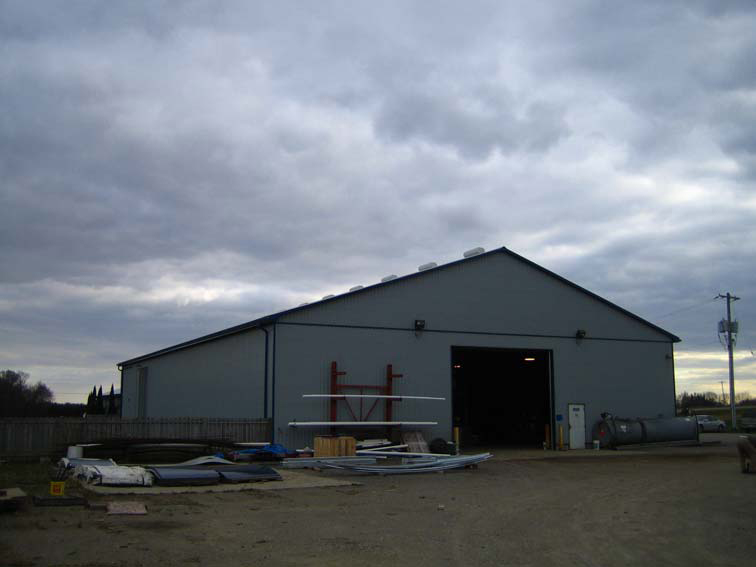 | N/A NFBCC does not apply. | 55.9 | 32,573.00 | 583 |
| 8 | 2002 single-storey post-framed swine barn | 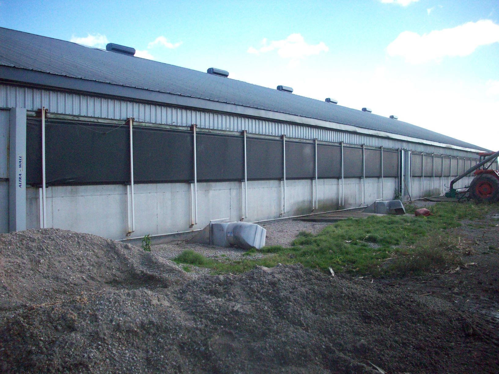 | Y | 55.9 | 15,364.50 | 275 |
| 9 | circa-1975 single-storey drive shed | 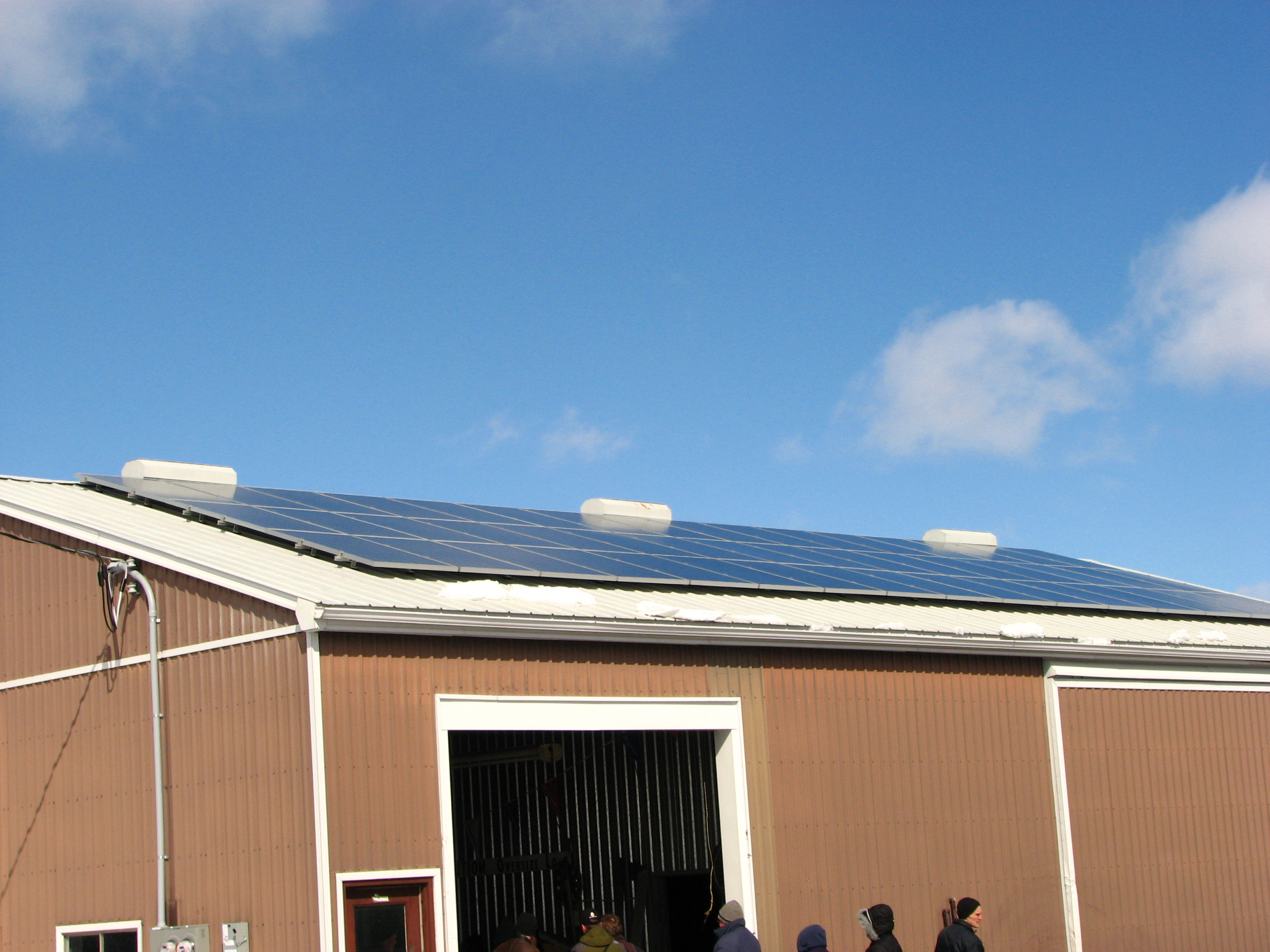 | N | 10.8 | 6,802.09 | 630 |
Factors affecting engineering and reinforcing costs
The age of the structure is one of the most important factors affecting reinforcement costs. Many older barns must be reinforced and/or repaired to bring them in line with current code requirements. Any non-standard connections must be reviewed with care since they aren’t encountered very often and are unique to that construction.
The grading of the lumber in older buildings impacts the amount of reinforcing required. For timber members, a substantial strength difference exists between the low, medium and higher grades. As a result, structures with lower grade timbers require more cost for reinforcement. Expect additional costs if the lumber needs to be accurately identified by a wood grader.
The amount of reinforcing required impacts the total cost. Some buildings only need one component (for example, the trusses) reinforced because there is reserve capacity everywhere else in the building. Once other structural members are involved, expect the cost to rise. For example, increasing the size of the footing requires a significant amount of time and money.
Older buildings are less likely to have drawings available. Where drawings are available and confirmed, more time can be spent on structural review and analysis, making the inspection of the building more cost-effective. If truss drawings are available, it is much easier to determine the reinforcing requirements, and this work can be completed more accurately. Some truss companies have software that allows for specific schedules to be easily produced.
The size of the structure is also important. Although the total cost of solar panel installation increases with the size of the building, with a larger rooftop solar installation, the fixed costs (for example, site visit) are spread out and the cost per kW often goes down.
Alternatives for structurally reinforcing a structure
In some cases, there is no cost-effective way to reinforce an existing structure so that crystalline silicon modules can be placed on the entire surface of the rooftop. For example, trusses with sloped bottom chords are problematic if the truss design forces are high and the connections are too tight to allow for adequate reinforcing. Figure 11 shows an example of such a truss. In these cases, engineers consider placing rows of modules close to the peak of the truss where there may be more strength. Snow is more likely to slide completely off the roof, and reinforcing requirements are reduced. Others may consider this option where it is too difficult to reinforce the structure. This might occur in small, insulated attic spaces where the process of delivering and properly installing the reinforcing material is very difficult.
Another way to overcome this challenge is to select a different technology type. For example, amorphous silicon (thin film) weighs less than crystalline silicon (c-Si) modules and in some cases can be installed such that the slippery roof design factor still applies. Figure 12 shows an example of a thin film installation.
In these cases, review the total amount of revenue generated along with the reduced reinforcing costs to help determine if this is a good alternative for the project. Consider a similar approach on the north side of a roof or another area receiving diffused sunlight. Although amorphous silicon does not produce as much electricity (in direct sunlight with southern exposure, for example) on a square-foot basis, it may perform better in situations with diffused light or other specific conditions.
Summary
Despite Ontario's northern latitude, much of the province has good solar exposure, and rural areas are particularly well placed to take advantage of it. Although the actual process of installing solar modules on a rooftop is not particularly difficult, the engineering work required to determine if the structure is suitable requires specialized knowledge.
Table 2 summarizes the information in this fact sheet and highlights some of the key questions that an engineer will need to answer in order to determine if a rooftop solar project is cost effective.
| Topic | Comment |
|---|---|
| Building windswept | The building may or may not have been designed using the wind exposure factor. This decision takes into account the current location of the building and proximity to obstructions, and what changes are likely to occur in the future. |
| Roof slope (slippery roof) factor | If the slippery roof factor was applied during the original design but does not apply now (due to the reasons discussed), the total roof design load could increase significantly. Lean-tos can prevent snow from sliding completely off the roof. |
| Installation of modules | Consider how any maintenance/ventilation rows impact snow-load calculations. When the fastener spacing is known, one can calculate the load transferred to the structure at each connection. |
| Quality and quantity of sunlight directed at the rooftop surface | In some cases, crystalline silicon is heavier, more efficient on a square-foot basis when subjected to direct sunshine and requires more reinforcing. Amorphous silicon is lighter, performs better in diffused light situations and requires less reinforcing. Landowners may choose to look at both solutions and compare the return on investment (ROI) to help make this decision. |
| Code requirements | If the structure was built before the latest code came into effect, it likely needs to be reinforced to meet current code requirements. The additional load due to the solar installation requires additional consideration. Some people are surprised that their newer buildings cannot support the additional load from a solar installation. Many modern buildings are designed so that the structural components precisely support the required loads and little more. As a result, even relatively small increases in total roof design load lead to reinforcing requirements. |
| Whole structure suitable for a rooftop solar installation | Many people focus on the roof trusses. An engineer will determine if other structural components, such as poles, beams, footings and lintels have adequate strength to support the additional load. Truss plates were mentioned, but the harsh atmospheric conditions can impact other structural members, such as steel base plates. |
| Building defects | The farm building could have corroding truss (gusset) plates, missing or damaged components, or inadequate bracing. These are all things that someone with specialized experience will review. |
| Work completed as per the original design assumptions | In most cases, the reinforcing plan is developed before the solar installation is complete. The plan incorporates what is typically required for a specific type of installation at a defined location on the roof. The quality of the reinforcing and the location of the rooftop solar project both need to be confirmed. |
| Oher details | There are other factors that are sometimes handled by the solar panel provider. The uplift requirements (how the rails are attached so the rails and modules don’t blow off the roof) is an example. As well, mixing dissimilar materials can lead to galvanic reactions and deterioration. The owner will want to know that the roofing material, rails and fasteners will work together without deteriorating prematurely. In other cases, the owner will want confirmation that there are no external factors that will shade the project or provide a source of excess dust and debris (for example, a ventilation unit). |
This fact sheet was updated by Steve Beadle, P. Eng., engineering specialist, swine and sheep housing and equipment, OMAFRA.