Tunnel ventilation in livestock barns, with and without evaporative cooling
Learn about tunnel ventilation design and management for livestock barns, which can help relieve heat stress in animals. This technical information is for Ontario livestock producers.
ISSN 1198-712X, Published March 2024
Introduction
Ontario's hot, humid summer weather makes it difficult for livestock and poultry to perform at their best. It is important to provide cooling in barns so that animals do not experience heat stress, resulting in an associated decrease in production.
The 2 most common cooling methods used in Ontario are air-based and water-based. This fact sheet discusses the design factors and management of tunnel ventilation – with and without evaporative cooling.
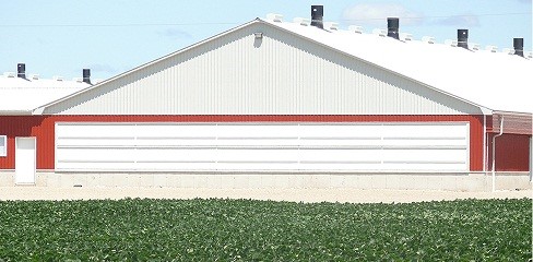
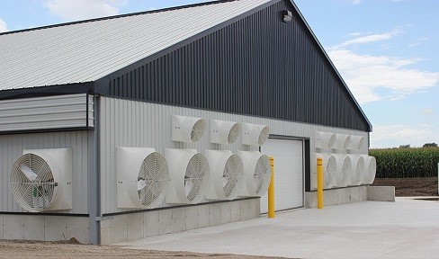
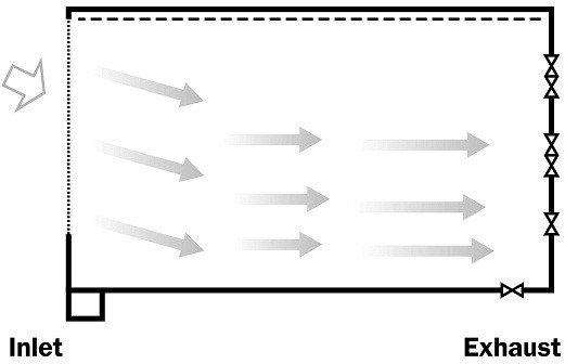
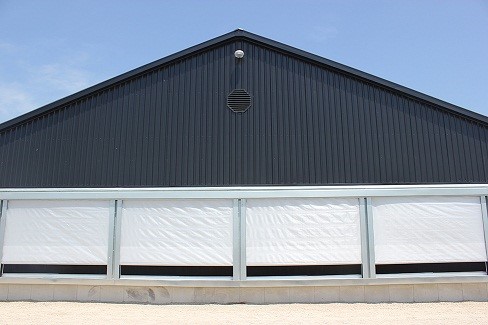
The main method of air-cooling livestock barns in Ontario is tunnel ventilation. The entire air inlet is located on one end wall of the barn (Figure 1) with all of the exhaust fans located on the opposite end (Figure 2). The idea is to create a high velocity wall of air moving down the long axis of the building like a wind tunnel. This provides a beneficial wind chill effect that cools the animals by convection (the removal of heat from the surface of an object by an airstream moving over it) and exhausts this heat out of the building.
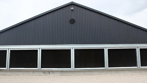
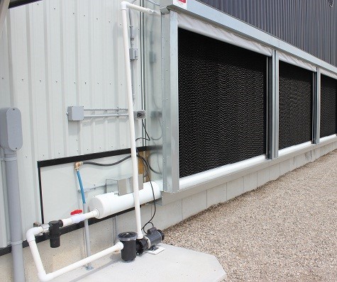
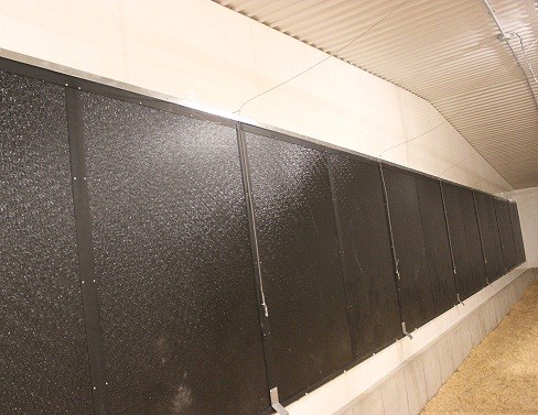
In many parts of the world, evaporative cooling pads are added to the air inlets of tunnel-ventilated barns (Figure 3) because there is a critical upper temperature for tunnel ventilation. Excessive air movement above 40°C — a chicken's core body temperature — will increase the heat stress experienced by the animal. At these high temperatures, some form of evaporative cooling is incorporated into the system to reduce the effects of the incoming air temperature.
With evaporative cooling, the incoming air is pulled through a saturated medium (cooling pad). The process of converting water from a liquid to a vapour removes heat energy from the incoming air, lowering its temperature but increasing its relative humidity.
Until recently, these systems were not commonly used in Ontario. However, following several summers with prolonged periods of temperatures higher than 30°C, these systems are being used in more barns.
Air-based cooling — tunnel ventilation
In a cross-flow ventilation system (air flows across the width of the building) with a slot-type air inlet, the air speed at the animal level ranges from 0.25 to 0.50 m/s (50–100 ft/min). With tunnel ventilation, the goal is to achieve an air speed of 1.0–2.5 m/s (200–500 ft/min) over the animals. The recent trend in Ontario and elsewhere is to design systems to operate at even higher airspeeds, with very good results.
Research conducted by the U.S. Department of Agriculture Poultry Research Laboratory at Mississippi State University on 7-week-old broiler chickens showed that air moving at 1 m/s (200 ft/min) over the birds results in similar growth rates to birds raised in still or slow-moving air that is 1°C cooler. Similarly, air moving at 2 m/s (400 ft/min) creates a wind chill effect of 3.7°C. The birds in this trial, grown under tunnel ventilation at 2 m/s, were 0.5 kg heavier at 7 weeks of age than the birds grown in still air.
Tunnel ventilation is not recommended when ambient air temperature is below 15°C or for sensitive, younger animals (baby chicks prior to feathering), as the wind chill–cooling effect is not necessary and could be stressful to these animals. For this reason, when tunnel ventilation is designed for a building, the normal cross-flow ventilation system is usually sized to supply 40–50% of the summer ventilation requirements to accommodate the three cooler seasons of the year and for the early growth stages of sensitive animals.
Fan capacity for tunnel ventilation
The size of the tunnel ventilation system is based on the amount of power needed to create a wall of air moving the length of the building at a velocity of 1.0–2.5 m/s (200–500 ft/min or 3.6–9 km/hr) or higher. Therefore, the required fan capacity is the useable barn cross-sectional area multiplied by the desired air speed. Note that floor-reared birds occupy the lower 0.3 m (1 ft) of the barn cross-section, so it is not useable for air movement. Similarly, cattle stalls or swine pen partitioning will reduce the net cross-sectional area available for airflow.
Air intake for tunnel ventilation
Tunnel ventilation inlets contain motorized louvers, curtains, panels or large doors. These openings are usually sized on the basis of 2 m2 per 5,000 L/s (2 ft2/1,000 CFM) of fan capacity. Since air does not easily turn corners, this type of inlet works best when located across an end wall so that the incoming fresh air travels straight into the barn in the correct airflow direction.
As shown in Figure 1, a large panel door across the end wall provides the necessary cross-sectional area for the air intake. Some barns are equipped with a combination of panels and a roll-up door to achieve the required inlet opening.
Tunnel ventilation control
Tunnel ventilation is strictly a warm-weather system and should only be used in temperatures above 21°C for animals that are not overly sensitive to drafts, such as birds older than 3 weeks of age.
As with normal cross-flow ventilation, stage the tunnel ventilation system to automatically turn on when the barn temperature increases. Typically, when using single speed, belt drive fans, 2 or 3 tunnel stages are used to manage the barn conditions. For example, Stage 1 operates the first group of 2 or 3 tunnel fans, Stage 2 operates another group of fans and Stage 3 operates the remaining fans. This control strategy allows a staggered wind chill effect to match the ambient air conditions experienced by the animals. As the temperature increases through the day, the corresponding stages are activated to create more air flow and as the cooler night temperatures arrive, the stages are deactivated in reverse order to decrease air flow.
Shifting to VFD fans changes how the controller is set to operate the system and allows a more gradual fan transition as the barn temperature Increases or decreases through the day. As ambient temperatures begin to rise, a large number of these VFD fans may be activated but only operate at 30–50% speed which uses less energy than same size fan operating at 100%. As the temperature continues to rise the controller will either add additional fans at low speed or increase the speed of previously operating fan(s) proportionally until all fans are operating at 100% when maximum the temperature setting is reached. Conversely, when ambient temperature begins to cool as night approaches, the controller will begin to slow the fan speeds and eventually shut down some of the excess capacity.
Normally the cross-flow ventilation system is turned off completely once the tunnel fans/inlets are activated. The sidewall fans are turned off, and the baffle board air inlet is closed to get the full wind-tunnel effect down the length of the barn. Remember, the main objective is to remove the hot air in the barn, as quickly as possible.
Potential tunnel airflow challenges
Air inlet location
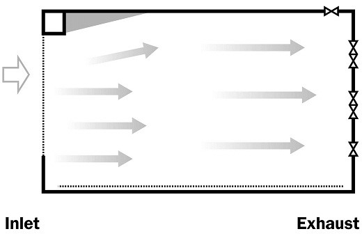
Locate air inlets on the end wall if at all possible. Air will not turn 90° corners unless forced. Any air entering from the sidewall creates airflow across the barn rather than along the length. Airflow from the sidewall inlet will eventually turn and move endwise to the exhaust fans but will leave a dead air zone (Figure 4) along the sidewall containing the inlet panel.

Service or entrance room location
Locate the service or entrance room outside the main building, as shown in Figure 1, to provide full end wall exposure for the tunnel air inlet. Besides reducing the available end wall opening, it creates a major wind shadow down that side of the room.
An unconfined air stream will fan out at about a 10° angle, and a 2.4-m (8-ft) wide service room will prevent tunnel air movement along that wall for at least 14 m (46 ft) (Figure 5). Smoke testing shows the actual affected distance is even greater due to a slow, backward eddy-type flow in the wind shadow area. If an interior room is necessary, locate it near the tunnel exhaust fans and opposite the winter air inlet to minimize the amount of airflow blocked.
Outside wind effect
Significant summer winds, blowing at an angle into the tunnel air inlet, can direct the airflow inside to one side of the barn (Figure 6). This situation drastically reduces the airflow along the other side of the room. Compare an outside wind speed of 20 km/hr (12.5 mph) to a typical tunnel air speed of 6 km/hr (3.8 mph) to understand the potential for the wind to overpower the airflow pattern. Opening the side air inlet baffle board to introduce more air to the side with less airflow can help even out the airflow. Air-deflecting baffles located at the tunnel inlet have also reduced this problem.
Ceiling air deflectors
A method of increasing the air speed at animal level, without installing extra tunnel fans, is to install drop curtains or other air deflectors from the ceiling every 12–25 m (40–80 ft) along the length of the barn to reduce the barn cross-sectional area.
Limit the increased air speed to a maximum of 2.5 or 3.0 m/s (500 or 600 ft/min) to prevent a reduction in fan performance. This is because too much reduction in the building cross-sectional area will increase the static pressure the fan(s) has to work against.
Evaporative cooling equipment
Design
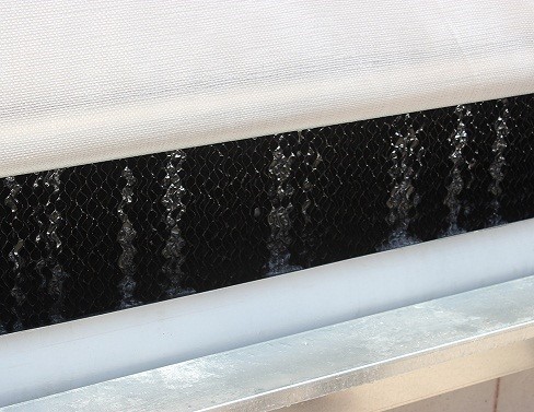
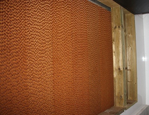
The evaporative cooling pad is made of fibrous material woven together, similar to corrugated cardboard, with large gaps in the grooves. The pad is mounted vertically over the tunnel air intake. The bottom of the pad sits in a drain trough, and a water delivery pipe, with evenly spaced holes, runs across the top of the pad.
A circulating pump is used to pump the water from the trough at the bottom of the pad to the distribution pipe at the top of the pad. When evaporative cooling is needed, the controller activates the pump, which delivers water to the distribution pipe that trickles water down the face of the pad to wet it.
Fresh water is added into the system via a float mechanism to replenish the water that is evaporated into the air stream during the ventilation process (Figures 7–10).
The cooling capability or efficiency of the pad system is directly related to pad type, size of pad and the air velocity allowed to pass through the pad. The cooling efficiency ranges from 55–75% for most evaporative cooling pads. Air velocity and size of the pad are directly related to the fan's capacity. A smaller pad area means a higher air velocity through the pads. Most pad manufacturers recommend a design air velocity of 1.27-1.78 m/s (250–350 fpm) through their pads to ensure a long enough contact time between the air and the wet surface to achieve the best cooling efficiency.
The most common design problem seen with evaporative cooling systems is not enough pad area. Since the wet cooling pad presents a greater barrier to air flow than a typical tunnel inlet, designers usually increase the size of the inlet opening for the evaporative cooling pad to ensure the static pressure drop across the pad is "limited to" 7.47–22.4 Pa (0.03-0.09 inches) water column. The recommended inlet opening size is 2.5 m2 of opening/5,000 L/s (2.5 ft2 of opening/1,000 CFM).
Evaporative cooling, like all water-based cooling systems, increases the relative humidity of the air in the barn space. Ensure the relative humidity in the barn never exceeds 80% when using an evaporative cooling pad during warm weather, as this may cause the animals more distress. For example, poultry pant to shed heat at higher temperatures (25°C+). This method of controlling body temperature relies on evaporative cooling within the bird's own lungs to get rid of excess heat from its body. However, when the bird is placed in a barn with a relative humidity greater than 80%, it cannot release heat. The ability of the room air to absorb any additional moisture above 80% is slowed or lessened. Since the bird is unable to lose this excess heat, its core body temperature begins to rise.
Water supply (quality and quantity)
Water used for cooling needs to be very clean to prevent blockage or fouling of the system. A filter is added to the water feedline to remove sediment. Treat hard water through a softener to avoid issues of scaling on the pads and to remove high levels of minerals (such as iron).
When considering the addition of evaporative cooling to your barn, ensuring an adequate water supply is important to evaluate. The cooling system requires this water at the same time that the animals are usually drinking more due to the high temperatures so having an adequate well/storage tank is a must.
To lower air temperature 0.55°C (1°F) requires evaporating 0.5 L (0.125 gallons) of water per hour for every 1000 CFM of airflow pulled through the pads.
To lower the barn temperature by 5°C (9°F) for the example broiler chicken barn (18-m × 91-m × 2.7-m (60-ft × 300-ft × 9-ft)), with a target air speed of 107 m/min (350 ft/min), the required flow rate for this one cooling system would be:
Operation
With a recirculating pump system, the most important factor to monitor is the small holes in the distribution pipe along the top of the evaporative cooling pad. Ensure these holes are not plugged and allow water to continually flow evenly across the pad, as this is essential for good cooling performance. If the pad is always streaking or there are dry spots on the pad, the distribution system likely needs cleaning and/or flushing.
Common reasons for a pad becoming plugged:
- High mineral content of feed water. This can result in mineral deposits or scale forming on the pad. To avoid this problem, treat the water used for the evaporative cooling pad through a water softener to remove the minerals.
- Algae growth. Since the pad is made of organic material and kept in a warm moist state, algae have a chance to grow on the pad and in the water collection sump. It is highly recommended to allow the pad to dry out at least once daily. Add approved algaecides to the collection sump to discourage algae growth: check with the manufacturer for a list of approved products.
The pad materials decay over time due to the repeated wet/dry cycles and should be replaced every couple of years. Some corrugated plastic pad materials have been tested to determine if they would provide a longer-lasting term alternative to current cardboard pads. These pads would not promote algae growth since the plastic is non-organic. However, the performance of the plastic pads, in terms of water evaporation, was not as good as the cardboard pads.
Winter maintenance
Completely drain the evaporative cooling systems before freezing temperatures arrive to prevent damage to the piping and pump.
To protect the pad materials from damage caused by ultraviolet light, snow or ice, during the winter months when it is not in use, place a watertight protective structure over the outside of the pad (Figure 11).
To prevent moisture migration and heat loss through the pad from inside the barn during colder temperatures, install air-tight, insulated panels on the inside of the tunnel inlets opening (refer to Figure 10).
Tunnel ventilation and evaporative cooling systems are effective methods for relieving heat stress and enhancing animal performance in hot weather. Both systems require careful design, operation and regular maintenance in order to make them work effectively.
Author credits
This fact sheet was written by Daniel Ward, P. Eng., poultry and other livestock housing and equipment, Ministry of Agriculture, Food and Rural Affairs (OMAFRA) and reviewed by Steve Beadle, P. Eng., swine and sheep housing and equipment, OMAFRA, Al Dam, poultry specialist, OMAFRA and Arlene Robertson, education coordinator, OMAFRA.