Government Notices — Other
Ontario Securities Commission
Ontario Securities Commission Rule 72-503 Distributions Outside Canada and Consequential Amendments
On March 31, 2018, Ontario Securities Commission Rule 72-503 Distributions Outside Canada and consequential amendments (Rule 72-503 and Consequential Amendments) became effective under the Securities Act.
The purpose of Rule 72-503 and Consequential Amendments is to bring greater clarity and certainty for market participants when offering securities to investors outside Canada.
The full text of Rule 72-503 and Consequential Amendments is available in the Ontario Securities Commission’s Bulletin at 2018 41 OSCB 2363 and on the Commission’s website at www.osc.gov.on.ca.
(151-G156)
Ontario Energy Board
Amendments to the Tranmission System Code
March 15, 2018
Section 3B of the Transmission System Code is amended by adding new sections as follows:
3B Reliability and Integrity of Transmission System
3B.2 Cyber Security
3B.2.1 Definitions
- “Cyber Security”
- means a body of technologies, processes, and practices designed to protect networks, computers, programs, data and personal information from attack, damage or unauthorized access. Cyber security includes electronic security and physical security issues as they relate to cyber security protection.
- “Cyber Security Framework”
- means the Ontario Cyber Security Framework that was issued December 20, 2017, or the current version of the document
3B.2.2 Reporting
3B.2.2.1
A transmitter shall report to the Board on the status of cyber security readiness referencing the Cyber Security Framework at such times and in such a manner as may be directed by the Board.
3B.2.2.2
The Chief Executive Officer of the transmitter shall certify the transmitter’s reported cyber security readiness in such form as may be required by the Board.
3B.2.3 Continuing Obligations Regarding Transmission System and Privacy
Nothing in this section 3B.2 shall limit any obligations of a transmitter to maintain the reliability and integrity of its transmission system, and to protect personal information.
(151-G157)
Amendments to the Distribution System Code
March 15, 2018
Section 1.2 of the Distribution System Code is amended by adding new definitions as follows:
1.2 Definitions
- “Cyber Security”
- means a body of technologies, processes, and practices designed to protect networks, computers, programs, data and personal information from attack, damage or unauthorized access. Cyber security includes electronic security and physical security issues as they relate to cyber security protection.
- “Cyber Security Framework”
- means the Framework Ontario Cyber Security Framework that was issued December 20, 2017, or the current version of the document.
Section 6 of the Distribution System Code is amended by adding new section 6.8 as follows:
6.8. Cyber Security
6.8.1 Reporting
6.8.1.1
A distributor shall report to the Board on the status of cyber security readiness referencing the Cyber Security Framework at such times and in such a manner as may be directed by the Board.
6.8.1.2
The Chief Executive Officer of the distributor shall certify the distributor’s reported cyber security readiness in such a form as may be required by the Board.
6.8.2 Continuing Obligations Re-Distribution System and Privacy
Nothing in this section shall limit any obligations of a distributor to maintain the reliability and integrity of its distribution system, and to protect personal information.
(151-G158)
Amendments to the Natural Gas Reporting and Record Keeping Requirements—Rule for Gas Utilities
March 15, 2018
Note: The text of the amendments is set out in italics below, for ease of identification only.
1. Section 1.8 is amended to add in the following in at the end of the section:
Sections 2.1.20 and 2.1.21 of this Rule, made by the Board on March 15, 2018, come into force on March 15, 2018 and are applicable to all filings due on or after that date.
2. Section 2.1 is amended to add in the following sections:
2.1.20 A utility shall provide in the form and manner required by the Board, annually, by the last day of the fourth month after the financial year end, the following information:
- whether or not the utility has publicly traded securities; and
- a list of affiliates of the utility that have publicly traded securities (affiliate has the same meaning as in the Ontario Business Corporations Act).
2.1.21 A utility shall provide in the form and manner required by the Board any changes to its status with respect to having publicly traded securities or any changes to its list of affiliates that have publicly traded securities within 10 days of the change occurring.
(151-G159)
Proposed Amendments to the Transmission System Code
April 30, 2018
2. definitions
| First version | Current version |
|---|---|
2.0.46
|
2.0.46
|
2.0.47A
|
|
2.0.55
|
2.0.55
|
6. customer connections
6.1 General Requirements
| First version | Current version |
|---|---|
| 6.1.5 |
6.1.5 Intentionally left blank. |
| 6.1.6 The Board may, on application or on its own motion, amend a transmitter’s connection procedures and any amendments thereto that have been previously approved by the Board. | 6.1.6 The Board may, on application or on its own motion, amend a transmitter’s connection procedures and any amendments thereto that have been previously approved or amended by the Board. |
| 6.1.7 |
6.1.7 Intentionally left blank. |
| 6.8.3 Where a transmitter had an executed agreement with a neighbouring Ontario transmitter on, the parties shall amend that agreement as may be required to ensure that it complies with the requirements of sections 6.8.1 and 6.8.2. Such amendment shall be made as soon as any other amendment to the agreement is being made by the parties and in any event no later than |
6.8.3 Where a transmitter had an executed agreement with a neighbouring Ontario transmitter on August 26, 2013, the parties shall amend that agreement as may be required to ensure that it complies with the requirements of sections 6.8.1 and 6.8.2. Such amendment shall be made as soon as any other amendment to the agreement is being made by the parties and in any event no later than August 26, 2018. |
8 general technical requirements
| First version | Current version |
|---|---|
| 8.1 |
8.1 Intentionally Left Blank |
8.2 Protection and Control
| First version | Current version |
|---|---|
| 8.2.1j) the two protection systems shall be supplied either from separate secondary windings |
8.2.1j) the two protection systems shall be supplied either from separate secondary windings of a voltage and current transformer or from separate voltage and current transformers.; and |
8.3 Insulation Coordination
| First version | Current version |
|---|---|
| 8.3.2 |
8.3.2 The transmitter shall ensure that a tap connected to a shielded transmission circuit is also be shielded. |
9. technical requirements for tapped trans-former stations supplying load
9.1 Supply Considerations
| First version | Current version |
|---|---|
| 9.1.2 The |
9.1.2 The transmitter shall ensure that the grounding of power transformer windings at tapped transmission system stations do not adversely affect the reliability of the transmission system. |
9.2 Protection Requirements
| First version | Current version |
|---|---|
| 9.2.1 The |
9.2.1 The transmitter’s protection and teleprotection requirements will be identified in the connection agreement. These requirements apply to the facilities that interface between the customer and the transmitter systems. Typical technical requirements for a transmitter’s tapped transformer stations protection are set out in Exhibit E.1, Schedule E of the applicable version of the connection agreement set out in Appendix 1, and Exhibits F.1 and F.2, Schedule F of version A of the connection agreement set out in Appendix 1. |
| 9.2.2 |
9.2.2 Intentionally left blank. |
| 9.2.3 |
9.2.3 Intentionally left blank. |
| 9.2.4 |
9.2.4 Intentionally left blank. |
| 9.2.5 |
9.2.5 Intentionally left blank. |
10 protection system requirements
10.1 Telecommunications
| First version | Current version |
|---|---|
| 10.1.2 A transmitter shall specify to all customers telecommunication channel media and protective systems. | 10.1.2 A transmitter shall specify to all customers telecommunication channel media and protective systems in the connection agreement. These requirements shall apply to the facilities that interface between the customer and the transmitter systems. |
| 10.1.4 |
10.1.4 Intentionally left blank. |
| 10.1.6 |
10.1.6 The transmitter shall include a maximum annual specification on major disturbances caused by telecommunication failures in the connection agreement. |
| 10.1.7 |
10.1.7 The transmitter shall include a maximum annual specification for unavailability of the telecommunication protection for a single transmission system circuit and for two circuits in the connection agreement. |
| 10.1.8 |
10.1.8 The transmitter shall include a maximum annual specification for telecommunication false trip rate in the connection agreement. |
| 10.1.9 |
10.1.9 The transmitter shall include a maximum annual specification in the connection agreement for total transmission system circuit trips coincident with telecommunications failure. |
10.2 Test Schedule For Relaying Communication Channels
| First version | Current version |
|---|---|
10.3 Verification And Maintenance Practices
| First version | Current version |
|---|---|
| 10.3.1 |
10.3.1 The transmitter shall establish verification intervals for protection systems not otherwise covered by the requirements of a reliability organization. Verification is required after any change is made to an existing protection system. |
10.4 Functional Tests And Periodic Verification
| First version | Current version |
|---|---|
| 10.4.1 For direct current circuitry checks, a transmitter shall thoroughly check the logic of the auxiliary circuitry with the direct current applied and the initiating devices suitably energized to initiate the process. |
10.4.1 For direct current circuitry checks, a transmitter shall thoroughly check the logic of the transmitter’s auxiliary circuitry with the direct current applied and the initiating devices suitably energized to initiate the process. Operation or tripping of any interrupting or isolating device shall always be verified, as well as local and/or remote annunciation. |
10.5 Failure Protection For High Voltage Interrupting Devices
| First version | Current version |
|---|---|
| 10.5.4 A transmitter shall not use automatic ground switches for any transmitter owned new installations for triggering line protection operation |
10.5.4 A transmitter shall not use automatic ground switches for any transmitter owned new installations for triggering line protection operation. |
10.6 Instrument Transformers
| First version | Current version |
|---|---|
| 10.6.2 A transmitter shall ensure that current transformers are connected so that adjacent relay protection zones overlap. | 10.6.2 A transmitter shall ensure that current transformers are connected so that adjacent relay protection zones overlap and, where they do not overlap, shall ensure appropriate mitigation is provided. |
10.7 Battery Banks And Direct Current Supply
| First version | Current version |
|---|---|
| 10.7.1 |
10.7.1 The transmitter shall ensure that if either the battery charger fails or the AC supply source fails, the station battery bank shall have enough capacity to allow the station to operate for at least eight hours for a single battery system or at least six hours for each of the batteries in a two battery system. |
| 10.7.2 |
10.7.2 The transmitter shall ensure that critical DC supplies such as relay protection circuits and high voltage interrupters (HVIs) shall be monitored and alarmed. |
| 10.7.3 |
10.7.3 The transmitter shall ensure that all generating facilities connected to the transmission system, have two separately protected (fuse/breaker) and monitored DC station battery systems unless the transmitter and IESO determine otherwise. |
| 10.7.4 |
10.7.4 The transmitter shall ensure that tapped transformer stations, have at least one protected (fuse/breaker) monitored DC station battery system. The transmitter may specify that two systems are required. |
13 coming into force
13.0.1 This Code shall be in effect as of the date on which it is published in the Ontario Gazette, and as of that date replaces the Transmission System Code issued by the Board on August 26, 2013.
Appendix 1
Version A–Form of Connection Agreement for Load Customers schedule E
General Technical Requirements
| First version | Current version |
|---|---|
| 1.1 |
1.1 |
1.3. Protection and Control
1.3.1. The protection systems, which protects transmission system elements, shall be capable of minimizing the severity and extent of disturbances to the transmission system while themselves experiencing a first-order single contingency such as the failure of a relay protection system to operate or the failure of a breaker to trip. In particular:
| First version | Current version |
|---|---|
| 1.3.1.1. the elements designated by the Transmitter as essential to system reliability and security shall be protected by two protection systems. Each system shall be independently capable of detecting and isolating all faults on those elements. These elements shall have breaker failure protection, but breaker failure protection need not be duplicated. Both protection systems shall initiate breaker failure protection; | 1.3.1.1. the elements designated by the Transmitter or the IESO as essential to system reliability and security shall be protected by two protection systems. Each system shall be independently capable of detecting and isolating all faults on those elements. These elements shall have breaker failure protection, but breaker failure protection need not be duplicated. Both protection systems shall initiate breaker failure protection; |
| 1.3.1.3. the use of two identical protection systems |
1.3.1.3. the use of two identical protection systems should be avoided, because it increases the risk of simultaneous failure of both systems due to design deficiencies or equipment problems; |
| 1.3.1.10. the two protection systems shall be supplied from separate secondary windings; |
1.3.1.10. the two protection systems shall be supplied either from separate secondary windings of a voltage and current transformer or from separate voltage and current transformers; |
1.8. Procedures for Maintenance and Periodic Verification
| First version | Current version |
|---|---|
| 1.8.1. The Transmitter, using good utility practice, may specify the maintenance criteria and the maximum time intervals between verification cycles for those parts of Customers’= facilities that may materially adversely affect the transmission system. The obligations for maintenance and performance re-verification shall be stipulated in the appropriate schedule to this Agreement. | 1.8.1. The Transmitter, using good utility practice, may specify the maintenance criteria and the maximum time intervals between verification cycles for those parts of Customers’= facilities that may materially adversely affect the transmission system. The obligations for maintenance and performance re-verification shall be stipulated in the appropriate schedule to this Connection Agreement. |
Schedule F
| First version | Current version |
|---|---|
Additional Technical Requirements for Tapped Connections
|
Additional Technical Requirements for Tapped Connections: |
|
|
1.1. Supply Considerations
| First version | Current version |
|---|---|
| 1.1.4. |
1.1.4. Transmitter approval is required before grounding the neutral of power transformer windings at tapped transmission system stations. |
| 1.1.5. |
1.1.5. Customers shall participate in load shedding to meet reliability standards. |
| 1.1.6. A transmission system breaker of a |
1.1.6. A transmission system breaker of a Customer shall not autoreclose without Transmitter’=s approval. |
| 1.1.7. A |
1.1.7. A Customer shall not manually energize a Transmitter’=s line without the Transmitter’=s approval. |
1.2. Protection Requirements
| First version | Current version |
|---|---|
| 1.2.1. The typical technical requirements for |
1.2.1. The typical technical requirements for Customer protection shall be followed, as presented in Exhibit E.1 of Schedule E and Exhibits F.1 and F.2 of this Schedule F. |
Schedule G
Protection System Requirements
1.1 Telecommunications
| First version | Current version |
|---|---|
| 1.1.2 Transmitter shall specify telecommunication channel media and protective systems. | 1.1.2 The Transmitter shall specify to the Customer the telecommunication channel media and protective systems. These requirements apply to the facilities that interface between the Customer and the Transmitter. |
| 1.1.4. |
1.1.4. Intentionally left blank. |
| 1.1.6. Major disturbances caused by telecommunication failures shall have annual frequency of less than 0.002 per year from the dependability aspect and less than 0.002 per year from the security aspect. | 1.1.6. Major disturbances caused by telecommunication failures shall have annual frequency of less than 0.002 per year from the dependability aspect and less than 0.002 per year from the security aspect or as otherwise prescribed by the Transmitter. |
| 1.1.7. Telecommunication protection for a single transmission system circuit shall have an unavailability less than forty two (42) minutes per year, and for two circuits it shall be |
1.1.7. Telecommunication protection for a single transmission system circuit shall have an unavailability less than forty two (42) minutes per year, and for two circuits it shall be no more than four (4) minutes per year or as otherwise prescribed by the Transmitter. |
| 1.1.8. The telecommunication false-trip rate used as part of a protection system for a single transmission system circuit shall be not more than 0.1 false trips per year, and for two circuits it shall be not more than 0.001 false trips per year. | 1.1.8. The telecommunication false-trip rate used as part of a protection system for a single transmission system circuit shall be not more than 0.1 false trips per year, and for two circuits it shall be not more than 0.001 false trips per year unless otherwise prescribed by the Transmitter. |
1.1.9. Total transmission system circuit trips coincident with telecommunications failure shall be not more than 0.001 per year unless otherwise prescribed by the Transmitter.
1.2. Test Schedule for Relaying Communication Channels
| First version | Current version |
|---|---|
| 1.2.1. Communication channels associated with protective relaying shall be tested at periodic intervals to verify that the channels are operational and that their characteristics |
1.2.1. Communication channels associated with protective relaying shall be tested at periodic intervals in accordance with applicable reliability standards to verify that the channels are operational and that their characteristics are within specific tolerances. Testing should include signal adequacy tests and channel performance tests. The Transmitter shall establish testing intervals for any communication channels not otherwise subject to reliability standards. |
1.3. Verification and Maintenance Practices
| First version | Current version |
|---|---|
| 1.3.1. Customers shall perform routine verifications of protection systems |
1.3.1. Customers shall perform routine verifications of protection systems in accordance with applicable reliability standards. The Customer shall establish verification intervals for any protection systems not otherwise covered by the requirements of a reliability organization. The reverification period for those protections systems is to be entered in the agreement and initialed by the parties. A Customer shall re-verify after a change is made to an existing system. |
| 1.3.2. |
1.3.2. Intentionally left blank. |
| 1.3.3. |
1.3.3. Intentionally left blank. |
| 1.3.6. |
1.3.6. The Transmitter and the Customer shall consult on the functional test procedures. The tests shall not begin until the procedure is accepted by the Transmitter. If they cannot agree, the supply or continuity of supply shall depend on the performance of the tests that the Transmitter shall require. |
| 1.3.8. Customers shall make available to the Transmitter records of relay calibrations and protection verifications, so that records of the facility=s performance can be maintained. The specific records required shall be identified in this Agreement. | 1.3.8. Customers shall make available to the Transmitter records of relay calibrations and protection verifications, so that records of the facility’=s performance can be maintained. The specific records required shall be identified in this Connection Agreement. |
1.4.
Functional Tests and Periodic Verification
| First version | Current version |
|---|---|
| 1.4.3. For (DC) circuitry checks, the logic of the auxiliary circuitry |
1.4.3. For direct current (DC) circuitry checks, a Transmitter shall thoroughly check the logic of the Transmitter’s auxiliary circuitry and the Customer shall thoroughly check the Customer’s auxiliary circuitry with the DC applied and the initiating devices suitably energized to initiate the process. Operation or tripping all any interrupting or isolating devices shall always be verified, as well as local and/or remote annunciation. |
1.5. Failure Protection for High-Voltage Interrupting Devices (HVIs)
| First version | Current version |
|---|---|
| 1.5.2. |
1.5.2. The HVI failure protection will initiate remote or transfer trip circuits and opening of the motor-operated disconnection switch unless otherwise prescribed by the Transmitter. |
| 1.5.4. Automatic ground switches are not acceptable for any new installations for triggering line protection operation |
1.5.4. Automatic ground switches are not acceptable for any new installations for triggering line protection operation. |
1.6.
Instrument Transformers
| First version | Current version |
|---|---|
| 1.6.2. Current transformers |
1.6.2. Current transformers should be connected so that adjacent relay protection zones overlap. Where they do not overlap, the Transmitter may approve alternative mitigation at its discretion. |
1.7. Battery Banks and Direct Current Supply
| First version | Current version |
|---|---|
| 1.7.2. Critical DC supplies |
1.7.2. Critical DC supplies such as relay protection circuits and high voltage interrupters (HVIs) shall be monitored and alarmed. |
| 1.7.3. For all generating facilities connected to the transmission system, two separately protected (fuse/breaker) and monitored DC station battery systems are required. | 1.7.3. For all generating facilities connected to the transmission system, two separately protected (fuse/breaker) and monitored DC station battery systems are required unless the Transmitter and the IESO determine otherwise. |
| 1.7.4. For tap transformer stations, one protected (fuse/breaker) monitored DC station battery system is required unless two systems are specified by the Transmitter. | 1.7.4. For tapped transformer stations, one protected (fuse/breaker) monitored DC station battery system is required unless two systems are specified by the Transmitter. |
Appendix 1
Version B–Form of Connection Agreement For Generator Customers
Schedule E
General Technical Requirements
| First version | Current version |
|---|---|
| 1.1 Intentionally left blank. | |
1.3. Protection and Control
1.3.1. The protection systems, which protects transmission system elements, shall be capable of minimizing the severity and extent of disturbances to the transmission system while themselves experiencing a first-order single contingency such as the failure of a relay protection system to operate or the failure of a breaker to trip. In particular:
| First version | Current version |
|---|---|
| 1.3.1.1. the elements designated by the Transmitter as essential to system reliability and security shall be protected by two protection systems. Each system shall be independently capable of detecting and isolating all faults on those elements. These elements shall have breaker failure protection, but breaker failure protection need not be duplicated. Both protection systems shall initiate breaker failure protection; | 1.3.1.1. the elements designated by the Transmitter or the IESO as essential to system reliability and security shall be protected by two protection systems. Each system shall be independently capable of detecting and isolating all faults on those elements. These elements shall have breaker failure protection, but breaker failure protection need not be duplicated. Both protection systems shall initiate breaker failure protection; |
| 1.3.1.3. the use of two identical protection systems |
1.3.1.3. the use of two identical protection systems should be avoided because it increases the risk of simultaneous failure of both systems due to design deficiencies or equipment problems; |
| 1.3.1.10. the two protection systems shall be supplied from separate secondary windings |
1.3.1.10. the two protection systems shall be supplied from separate secondary windings of a voltage and current transformer from separate voltage and current transformers; |
1.8. Procedures for Maintenance and Periodic Verification
| First version | Current version |
|---|---|
| 1.8.1. The Transmitter, using good utility practice, may specify the maintenance criteria and the maximum time intervals between verification cycles for those parts of Customers’= facilities that may materially adversely affect the transmission system. The obligations for maintenance and performance re-verification shall be stipulated in the appropriate schedule to this Agreement. | 1.8.1. The Transmitter, using good utility practice, may specify the maintenance criteria and the maximum time intervals between verification cycles for those parts of Customers’= facilities that may materially adversely affect the transmission system. The obligations for maintenance and performance re-verification shall be stipulated in the appropriate schedule to this Connection Agreement. |
Schedule F
Additional Technical Requirements
1.1 Supply Considerations
| First version | Current version |
|---|---|
| 1.1.5 |
1.1.5 Transmitter approval is required before grounding the neutral of power transformer windings at tapped transmission system stations. |
1.5 Autoreclosure and Manual Energization
| First version | Current version |
|---|---|
| 1.5.2 Following a protection operation on a transmission line, the transmission breakers, located mainly in network switching and/or transformation stations, shall autoreclose after a certain time delay. Where the Generator is directly connected to the transmission line, or for configurations where the Generator could be damaged by autoreclosure of the line, the Generator shall provide a reliable means of disconnecting its equipment before autoreclosure. The Generator is responsible for protecting its own equipment and the Transmitter is not liable for damage to the Generator’=s equipment except as stipulated in section 15 of this Connection Agreement. The Generator may request a means of supervising the transmission autoreclosure prior to the disconnection of its equipment e.g. changes in protection logic at one or both stations to reduce the risk of such events. The criteria governing the use of reclosures are set out in the Ontario Hydro |
1.5.2 Following a protection operation on a transmission line, the transmission breakers, located mainly in network switching and/or transformation stations, shall autoreclose after a certain time delay. Where the Generator is directly connected to the transmission line, or for configurations where the Generator could be damaged by autoreclosure of the line, the Generator shall provide a reliable means of disconnecting its equipment before autoreclosure. The Generator is responsible for protecting its own equipment and the Transmitter is not liable for damage to the Generator’=s equipment except as stipulated in section 15 of this Connection Agreement. The Generator may request a means of supervising the transmission autoreclosure prior to the disconnection of its equipment e.g. changes in protection logic at one or both stations to reduce the risk of such events. The criteria governing the use of reclosures are set out in the Ontario Hydro ”Policies, Principles & Guidelines” document A”C-3.4.1(R1), Automatic Reclosure and Manual Energization on Bulk System Electricity Circuits”@, which was in effect as of April 1, 1999. |
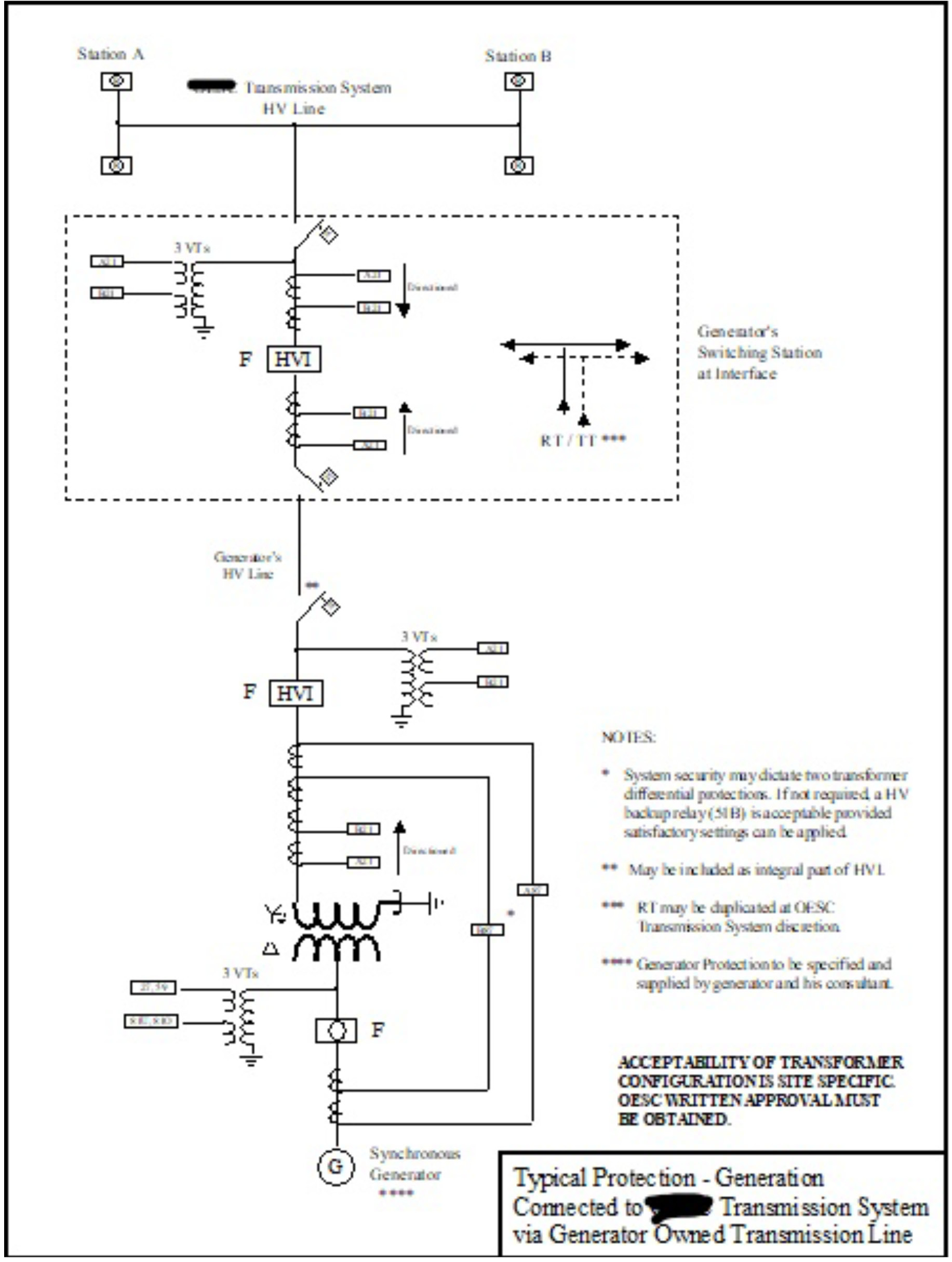
Exhibit F.2
Typical Generator-owned Transmission Line Protection Requirement
Schedule G
Protection System Requirements
1.1 Telecommunications
| First version | Current version |
|---|---|
| 1.1.2. |
1.1.2. The Transmitter shall specify to all Customers the telecommunication channel media and protective systems. These requirements apply to the facilities that interface between the Customer and the Transmitter. |
| 1.1.4. |
1.1.4. Intentionally left blank. |
| 1.1.6. Major disturbances caused by telecommunication failures shall have annual frequency of less than 0.002 per year from the dependability aspect and less than 0.002 per year from the security aspect. | 1.1.6. Major disturbances caused by telecommunication failures shall have annual frequency of less than 0.002 per year from the dependability aspect and less than 0.002 per year from the security aspect or as otherwise prescribed by the Transmitter. |
| 1.1.7. Telecommunication protection for a single transmission system circuit shall |
1.1.7. Telecommunication protection for a single transmission system circuit shall be unavailable for no more than forty two (42) minutes per year, and for two circuits no more than four (4) minutes per year or as otherwise prescribed by the Transmitter. |
| 1.1.8. The telecommunication false-trip rate used as part of a protection system for a single transmission system circuit |
1.1.8. The telecommunication false-trip rate used as part of a protection system for a single transmission system circuit is no more than 0.1 false trips per year, and for two circuits is no more than 0.001 false trips per year unless otherwise prescribed by the Transmitter. |
1.1.9. Total transmission system circuit trips coincident with telecommunications failure shall be not are not more than 0.001 per year unless otherwise prescribed by the Transmitter.
1.2. Test Schedule for Relaying Communication Channels
| First version | Current version |
|---|---|
| 1.2.1. Communication channels associated with protective relaying shall be tested at periodic intervals to verify that the channels are operational and that their characteristics lie are within specific tolerances. |
1.2.1. Communication channels associated with protective relaying shall be tested at periodic intervals in accordance with applicable reliability standards to verify that the channels are operational and that their characteristics lie are within specific tolerances. Testing should include signal adequacy tests and channel performance tests. The Transmitter shall establish testing intervals for any communication channels not otherwise subject to reliability standards. |
1.3. Verification and Maintenance Practices
| First version | Current version |
|---|---|
| 1.3.1. Customers shall perform routine verifications of protection systems on a scheduled basis in accordance with applicable reliability standards. |
1.3.1. Customers shall perform routine verifications of protection systems on a scheduled basis in accordance with applicable reliability standards. The Customer shall establish verification intervals for any protection systems not otherwise covered by the requirements of a reliability organization. The reverification period for those protection systems is to be entered in the agreement and initialed by the parties. The Customer shall re-verify after a change is made to an existing protection system. |
| 1.3.2. |
1.3.2. Intentionally left blank. |
| 1.3.3. |
1.3.3. Intentionally left blank. |
| 1.3.6. The Transmitters and Customers shall |
1.3.6. The Transmitters and the Customers shall consult on the functional test procedures. The tests shall not begin until the procedure is accepted by the Transmitter. If they cannot agree, the supply or continuity of supply shall depend on the performance of the tests that the Transmitter shall require. |
1.4. Functional Tests and Periodic Verification
| First version | Current version |
|---|---|
| 1.4.1. Upon verification that the Customer’=s static tests on protection and control equipment, outlined in the Code and this Agreement have been satisfactorily completed, a series of tests shall be performed with the equipment in a dynamic mode. These tests shall ensure that the equipment performs correctly when it should and also that it will not operate improperly. | 1.4.1. Upon verification that the Customer’=s static tests on protection and control equipment, outlined in the Code and this Connection Agreement have been satisfactorily completed, a series of tests shall be performed with the equipment in a dynamic mode. These tests shall ensure that the equipment performs correctly when it should and also that it will not operate improperly. |
| 1.4.3. For (DC) circuitry checks, the logic of the auxiliary circuitry |
1.4.3. For direct current (DC) circuitry checks, the Transmitter shall thoroughly check the logic of the Transmitter’s auxiliary circuitry and the Customer shall thoroughly check the Customer’s auxiliary circuitry with the DC applied and the initiating devices suitably energized to initiate the process. Operation or /tripping of any interrupting or isolating devices shall always be verified, as well as local and/or remote annunciation. |
1.5. Failure Protection for High-Voltage Interrupting Devices (HVIs)
| First version | Current version |
|---|---|
| 1.5.2. |
1.5.2. The HVI failure protection will initiate remote or transfer trip circuits and opening of the motor-operated disconnection switch unless otherwise prescribed by the Transmitter. |
| 1.5.4. Automatic ground switches are not acceptable for any new installations for triggering line protection operation |
1.5.4. Automatic ground switches are not acceptable for any new installations for triggering line protection operation. |
1.6. Instrument Transformers
| First version | Current version |
|---|---|
| 1.6.2. Current transformers |
1.6.2. Current transformers should be connected so that adjacent relay protection zones overlap. Where they do not overlap, the Transmitter may approve alternative mitigation at its discretion. |
1.7.
Battery Banks and Direct Current Supply
| First version | Current version |
|---|---|
| 1.7.2. Critical DC supplies shall be monitored and. |
1.7.2. Critical DC supplies such as relay protection circuits and high voltage interrupters (HVIs) shall be monitored and alarmed. |
| 1.7.3. For all generating facilities connected to the transmission system, two separately protected (fuse/breaker) and monitored DC station battery systems are required. | 1.7.3. For all generating facilities connected to the transmission system, two separately protected (fuse/breaker) and monitored DC station battery systems are required unless the Transmitter and the IESO determine otherwise. |
| 1.7.4. For tapp transformer stations, one protected (fuse/breaker) monitored DC station battery system is required unless two systems are specified by the Transmitter. | 1.7.4. For tapped transformer stations, one protected (fuse/breaker) monitored DC station battery system is required unless two systems are specified by the Transmitter. |
(151-G160)