Transitioning to modular loading on the Ontario broiler chicken farm
Learn how modular loading systems work and how to transition to modular loading on broiler chicken farms. This technical information is for Ontario broiler chicken farmers.
ISSN 1198-712X, Published February 2020
Introduction
Modular loading is a proven handling system for transporting birds from the farm to processing facilities (Figure 1). It has already been successfully implemented in many jurisdictions within North America and around the world. Modular loading improves loading efficiency, bird welfare during handling and transport, meat quality and food safety. Pressure from consumers regarding animal welfare is driving the conversion to this new system.
This factsheet explains how modular loading systems work and the physical requirements needed to use this equipment. It also explains what modifications may be necessary to your pre-existing facilities to assist you in implementing the changes needed to use this equipment. If you are planning to build a new barn, this factsheet will also provide details that you should include in your planning to accommodate modular loading.
Modular loading systems
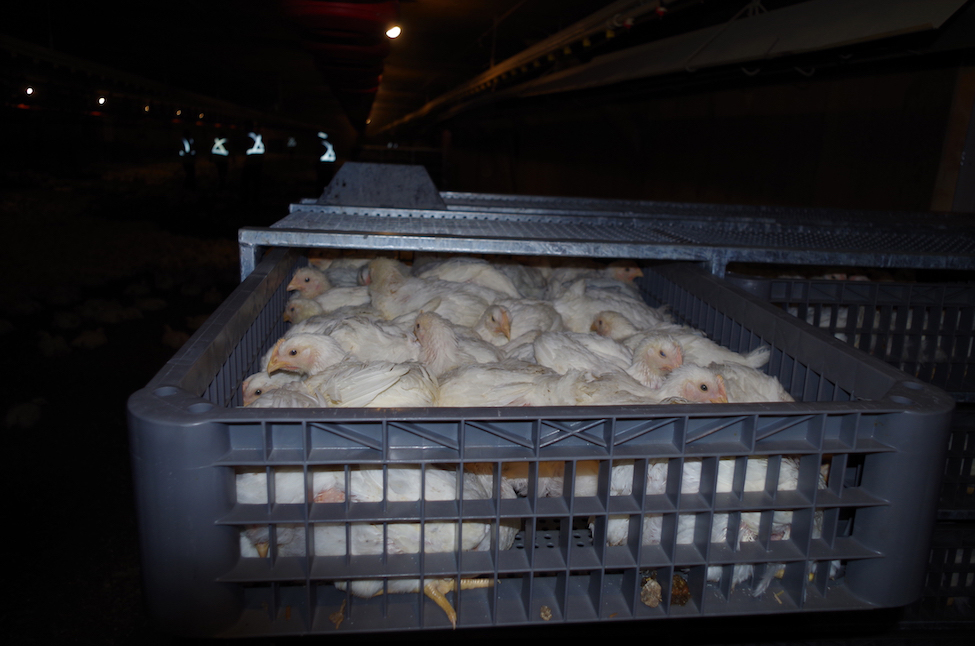
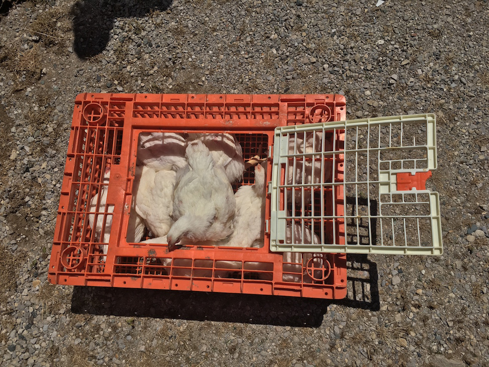
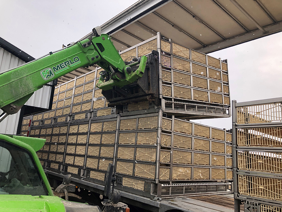
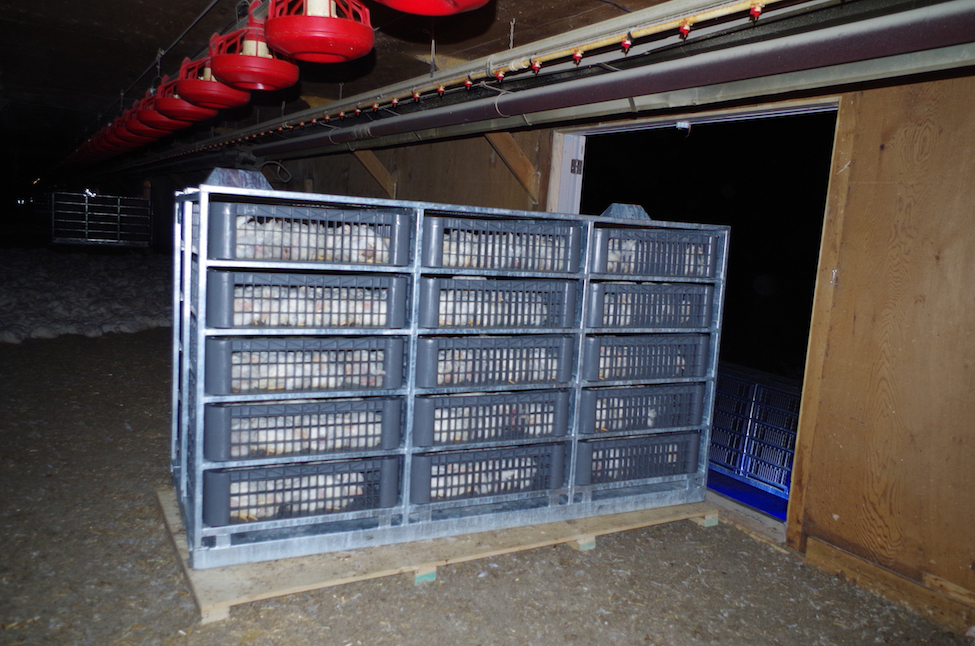
Modules are a series of molded plastic drawers set in a frame of welded metal tubing. Most companies use galvanized metal or stainless-steel frames to resist corrosion, as the equipment is washed daily after use. Each module is lifted off the truck with a forklift and placed within the barn where the chicken catchers catch and place the birds directly into the drawers. In the old crate loading system, the catchers would have caught the birds and carried them across the barn where the birds would be passed to other crew members, outside on the transport truck, to be placed into the crates. The opening at the top of these drawers is much larger than the standard chicken crate currently in use, allowing for a more humane placement of birds and faster load times. The reduced handling of the chickens and the larger drawer openings combine to reduce the risk of injury to the birds (Figures 2 and 3). Once all the drawers are filled, the forklift carries the module back to the truck.
Modular systems provide the opportunity for processing plants to incorporate gas stunning in the receiving area prior to shackling. This means that live birds are only handled once, from catch to shackle, resulting in further improvements in bird welfare, meat quality and food safety.
Module equipment
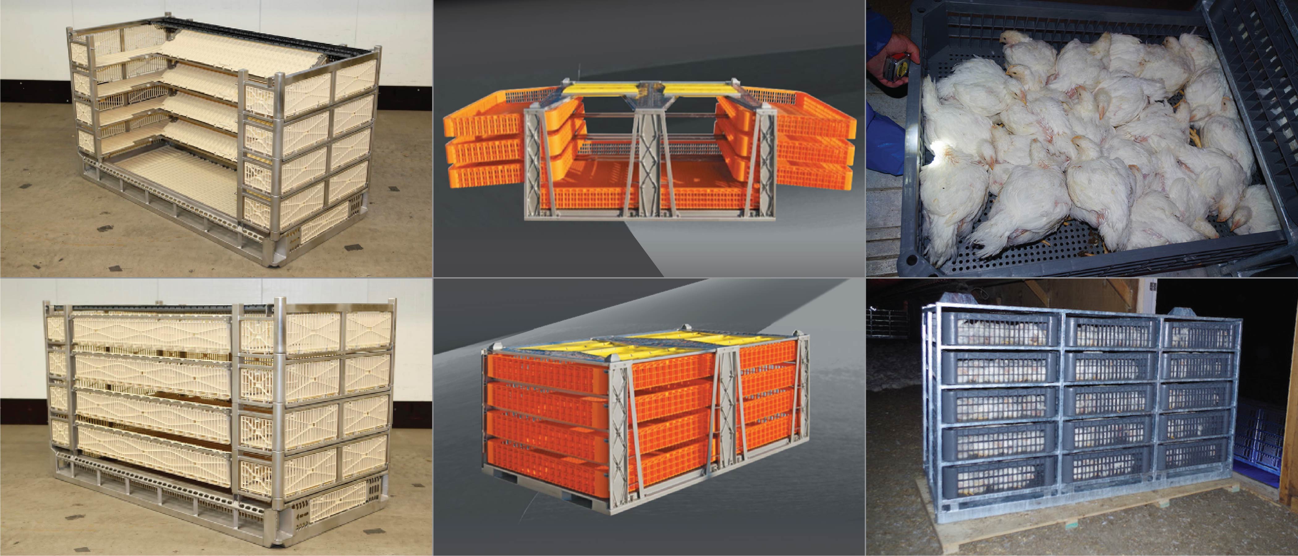
There are many companies supplying module equipment to the broiler industry including Anglia Autoflow, Bright Coop Ltd., Marel-Stork Poultry Processing, Meyn Food Processing and CM2A. See Figure 4 for several examples. Note that these manufacturers are listed as examples and as sources for additional research. The Ministry of Agriculture, Food and Rural Affairs (OMAFRA) does not specifically endorse or recommend any of these equipment manufacturers.
While there are subtle differences between each manufacturer’s equipment, such as number of drawers, module height, empty weights, etc., there are also some similarities, as this equipment must travel on regulation-sized highway trailers. Table 1 provides a comparison showing a 5-tier high, full trailer width module from three of the supply companies.
For the update of this document, the Meyn Maxiload twin 5-tier module was selected for determining the expected floor loads for the barns because it is the heaviest of the systems in use in Ontario.
| Manufacturer | Marel-Stork | Meyn Maxiload Twin | CM2A |
|---|---|---|---|
| # of drawers | 5 | 10 | 15 |
| Length of frame | 2,430 mm (95.7 in.) |
2,435 mm (95.9 in.) |
2,438 mm (96.0 in.) |
| Width of frame | 1,200 mm (47.3 in.) |
1,350 mm (53.1 in.) |
1,165 mm (45.9 in.) |
| Height of frame | 1,415 mm (55.7 in.) |
1,445 mm (56.9 in.) |
1,497 mm (58.9 in.) |
| Empty weight (frame + drawers) | 342 kg (754 lb) |
486 kg (1,069 lb) |
427 kg (939 lb) |
| Maximum loaded weight (frame + drawers + birds) |
1,122 kg (2,468 lb) |
1,441 kg (3,170 lb) |
1,225 kg (2,695 lb) |
| Bird weight/drawer | 160 kg (352.0 lb) |
95.5 kg (210 lb) |
53.2 kg (117.3 lb) |
Farm information
A 2010 study identified that the sheer number and variety of barns used for growing chickens in Ontario is the biggest implementation challenge for a modular loading system. In 2018, there were approximately 2,100 barns growing broiler chickens in Ontario. Of these, approximately 48.5% are single storey, 47.2% are two-storey and 4.3% are three-storey or greater. The age of these barns varies from new construction to older than 40 years.
Building sizes, construction techniques and building codes have evolved over the years to reflect changes in technology and management practices (e.g., the use of larger manure cleanout tractors). A 30-year old, two-storey barn that was built according to the building code of the day is considered legal non-conforming, but it was not designed for the heavier floor loads shown in more recent codes.
Accommodating loaded modules on a pre-existing second floor in a two-storey barn requires a structural assessment by an engineer. It may also require some structural reinforcing to ensure that the building can safely handle the anticipated loads.
Catching companies may require a signed engineering report after conversion work is complete. This will assure them that every reasonable precaution has been taken to protect their workers from structural failure. It will also provide the farmer with a guarantee that the barn will not be damaged from the weight of loaded modules.
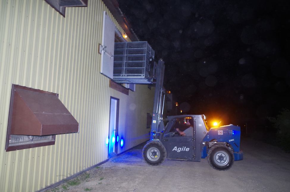
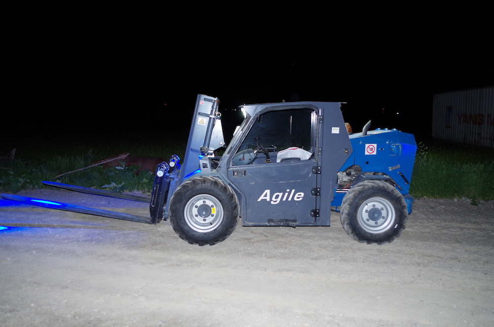
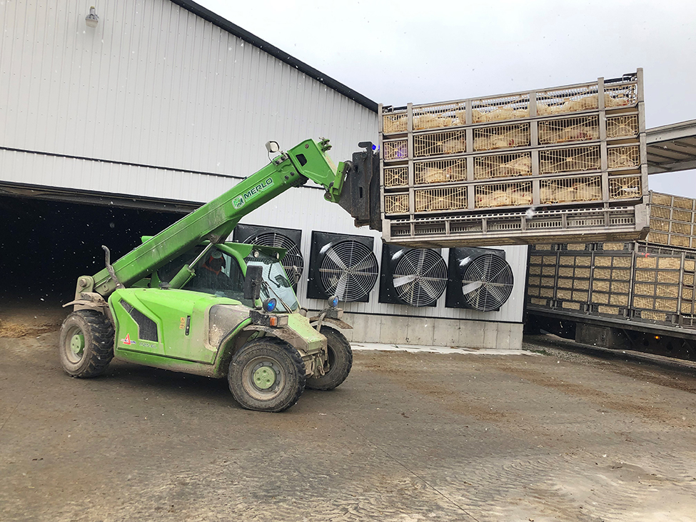
Forklift or telehandler information
The equipment required to move the modules at the farm site is quite specialized (Figure 5 and 6). It requires a low profile (mast height, cab height) to ensure that it can safely enter the barns without hitting equipment or the structure. It must be very maneuverable (tight turning radius) to work in restricted areas. It must also have the lift capability to handle the fully loaded modules and the reach to place these modules into second floor door openings.
Ideal new barn for modular loading
The ideal new broiler barn design, to realize the most benefit from modular loading technology, is a single-storey barn with a minimum 2.7-m (9-ft) ceiling height. The lack of internal support posts and high clearance allows for unimpeded forklift operation. Operators can place empty modules within a couple of feet of the chickens, allowing catchers to simply load the birds with little walking. A crew of six catchers and one forklift can load a 16.2-m (53-ft) transport trailer in 1 hr or less, from a single-storey barn.
The 2.7-m (9-ft) ceiling allows for a minimum of 2.4 m (8 ft) of clearance between litter and all suspended equipment (feed lines, waterlines, temperature/humidity sensors, etc.). Ideally, fixed equipment like gas lines and heating equipment or circulation fans should also have 2.4 m (8 ft) of clearance underneath or be located so they are not in forklift traffic lanes and have high reflective tape to improve visibility.
Remember that the forklift is normally operating at night in low lighting conditions, making it difficult to see hanging equipment. Uneven litter can also cause the forklift to bounce when carrying modules.
Minimum end wall doorway openings for a forklift should be 2.4 m high x 3.0 m wide (8 ft high x 10 ft wide) to allow for ease of access. For barns longer than 91.5 m (300 ft), provide a second forklift doorway of the same dimension at the opposite end of the barn. This will reduce the travel distance for the forklift operator during loadout, since half of the barn can be loaded from each end. The truck is then relocated to the other end of the barn to finish loadout. The forklift operator has to stay ahead of the catching crew bringing empty modules in a timely fashion so they are not standing around waiting. Excessive travel distances (>106 m (>350 ft)) or manoeuvring require more time to complete these tasks and will result in a decreased loading efficiency. The mid-barn loadout option is discussed later in this document as another method to reduce travel distance for the forklift.
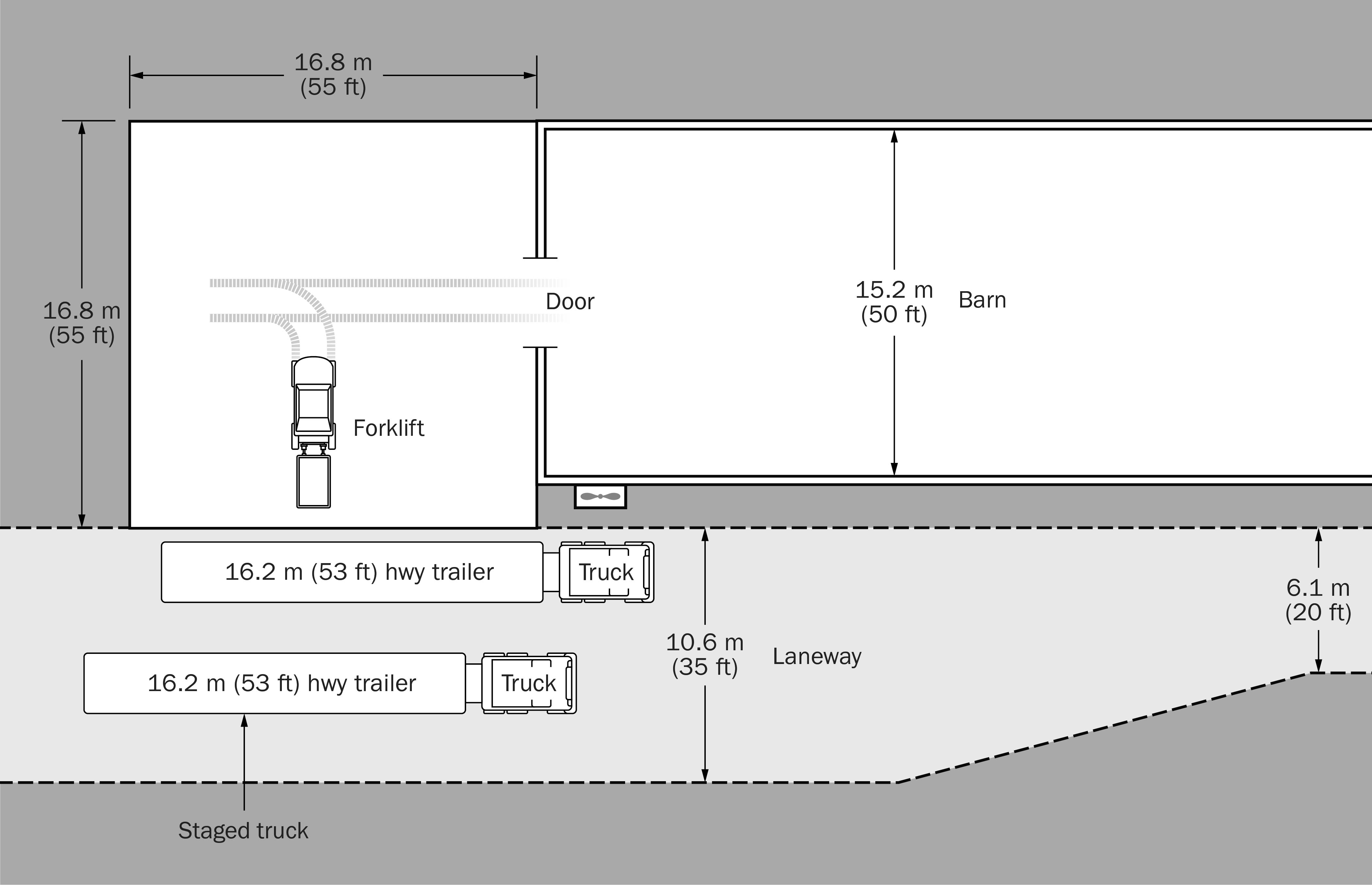
Locate a hard, level loading area (concrete or equivalent surface) measuring a minimum of 16.8 m x 16.8 m (55 ft x 55 ft) for a 15.2-m (50-ft) wide barn, immediately outside the doorway to allow for forklift travel and turning during loading/unloading of modules from the transport truck (Figure 7). Extend the pad 1.5 m (5 ft) beyond the side of barn to ensure the transport truck is located far enough out to avoid ventilation fans extending from the side of the barn.
| Barn width m (ft) | Minimum pad width m (ft) | Minimum pad length m (ft) |
|---|---|---|
| 12.2 (40) | 13.7 (45) | 16.8 (55) |
| 15.2 (50) | 16.8 (55) | 16.8 (55) |
| 18.2 (60) | 19.8 (65) | 16.8 (55) |
| 21.3 (70) | 22.9 (75) | 16.8 (55) |
| 24.4 (80) | 25.9 (85) | 16.8 (55) |
Pad area will vary with width of barn. See Table 2 for minimum recommended dimensions. The areas listed in Table 2 are the unimpeded area required for forklift travel, this does not include any areas used to stockpile broiler litter. There should be a smooth transition between the inside of the barn and this loading area (i.e., no door sills or abrupt grade changes), to prevent modules from bouncing during transport into or out of the barn by forklift. If the loading area is located on the same end of the barn as the solid manure storage, the pad may need to be extended to ensure the clear area (area not piled with manure) available for forklift travel meets the above listed minimums.
If the loading pad area consists of compacted gravel, maintenance of this area is critical for efficient forklift travel. No water ponding areas or potholes should be allowed, as this will greatly reduce forklift speed. The transport truck needs to be perfectly level in both directions during loading of the modules so the forklift can approach perpendicular to the trailer and efficiently place the module onto the locating pins on the deck or on top of the first layer module (Figure 8).
Mid-barn loadout door option
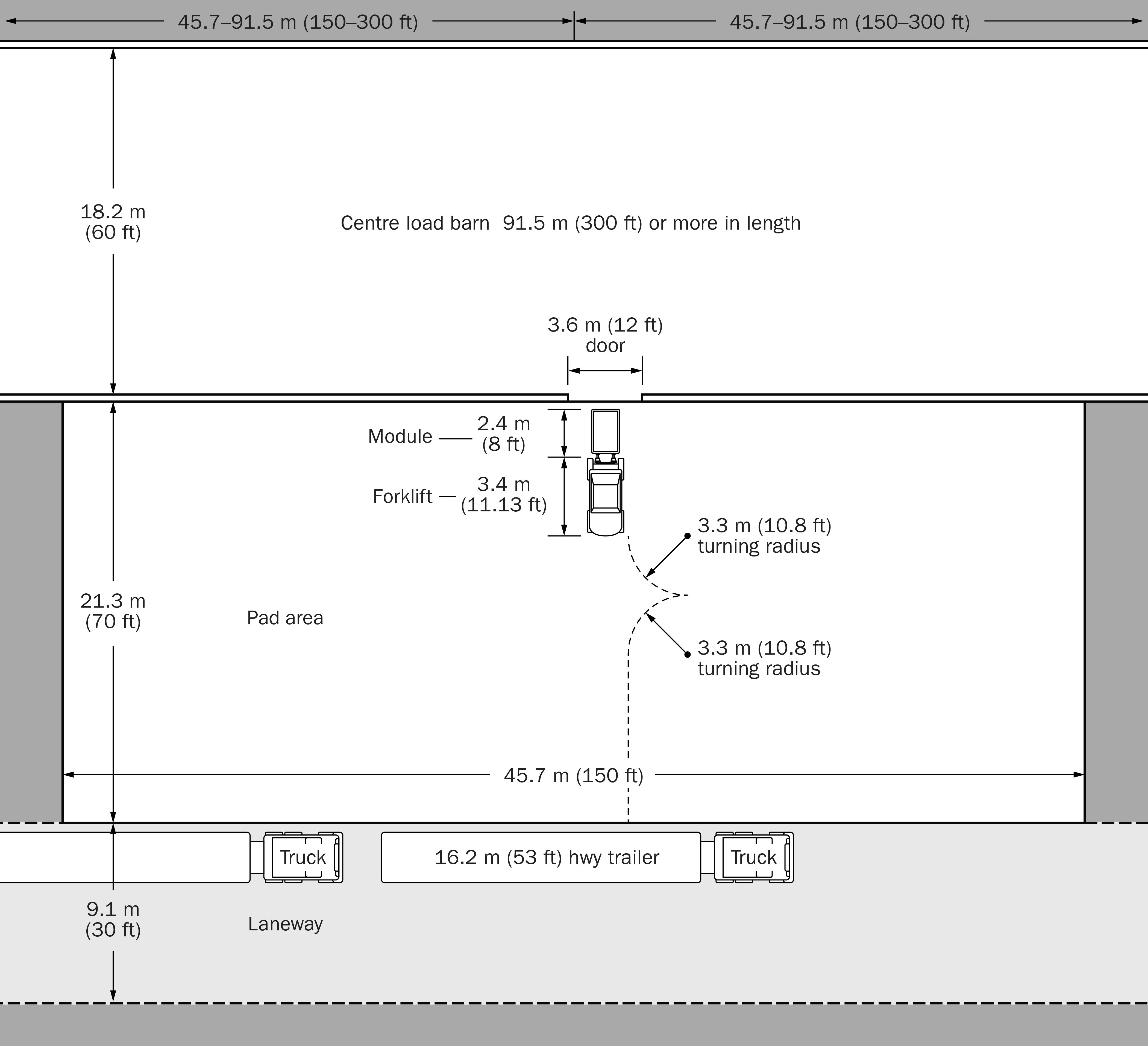
For barns greater than 91.5 m (300 ft) in length, instead of installing loadout doors at each end with associated loading areas, another option is to install one large door at the midpoint of the barn in one of the sidewalls. The door needs to be a minimum of 3.6 m (12 ft) long x 2.4 m (8 ft) high and have one loadout pad measuring 21.3 m (70 ft) wide x 45.7 m (150 ft) long (see Figure 9).
The pad should be sized to allow the forklift/telehandler to turn 180 degrees when picking a module off the transport trailer so the driver is not backing empty modules into the dark barn (as lights are off during night loading). Length of the pad allows the truck being loaded to advance the equivalent distance of a full module to minimize forklift side travel. Another advantage is that this allows staging of the next truck behind the current trailer being loaded so that as the current truck is being finished, the forklift can begin to pull empty modules from the next trailer to minimize stoppages in the loading process. The truck laneway needs to be wide enough to allow two transports to pass each other (so loaded trailers can leave the site while the next trailer is being loaded).
This loadout configuration is advantageous for tunnel ventilated barns (with or without evaporative cooling pads), as there is no reduction in end wall area available to mount ventilation equipment, since there are no large doors to work around.
Retrofitting existing barns to receive modules
Existing single-storey or ground floor of multi storey barns
Many older barns were built with 2.4 m (8 ft) ceilings on the first floor. This provides a minimum clearance height of 2.1 m (7 ft) between the litter and all suspended equipment. Verify the actual forklift mast and cab height prior to initial loadout to ensure sufficient clearance. Forklift makes and models may vary in height so if equipment is changed, clearance height should be reverified.
The minimum end wall doorway opening for the forklift should be 2.4 m high x 3.0 m wide (8 ft high x 10 ft wide) to allow for ease of access. For barns longer than 91.5 m (300 ft), provide a second forklift doorway of the same dimension at the opposite end of the barn or consider adding a mid-barn loading door in a sidewall. This will reduce the travel distance for the forklift operator during loadout.
Locate a hard, level loading area (concrete or equivalent surface) measuring 16.8 m x 16.8 m (55 ft x 55 ft) immediately outside the doorway to allow for forklift travel and turning during loading/unloading of modules from the transport truck (Figure 7). There should be a smooth transition between inside the barn and this loading area, i.e., no door sills or abrupt grade changes, to prevent modules from bouncing during transport into or out of the barn by forklift.
Unfortunately, there are some barns that may never be able to accommodate modular loading equipment, due to site restrictions or the prohibitive cost to retrofit these barns.
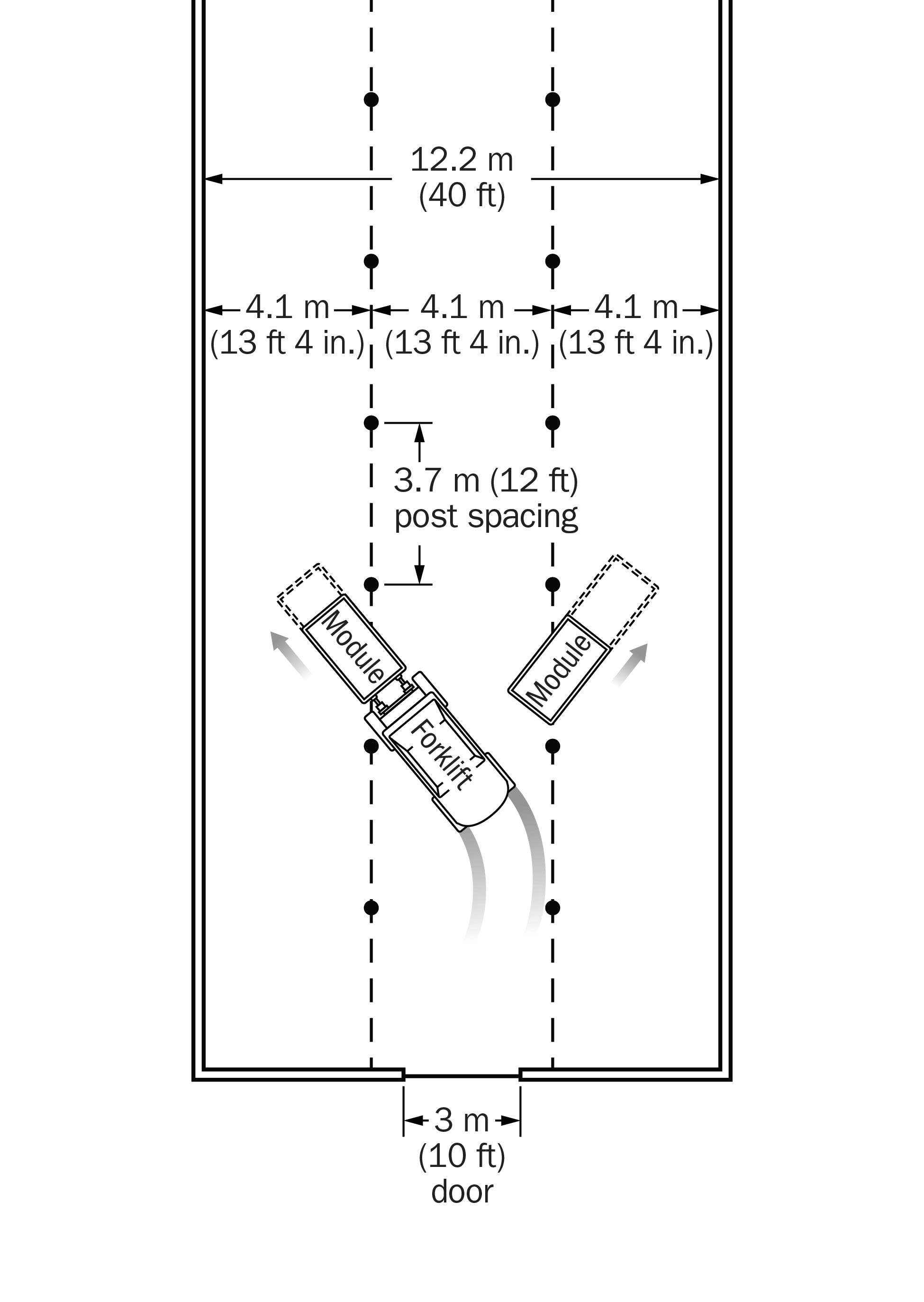
For the ground floor of multi-storey barns, the normal traffic pattern is down the middle of the barn between the rows of posts. In an ideal scenario, the posts are spaced far enough apart that a forklift can angle modules into openings between posts on opposite sides of the traffic lane (Figure 10). If the post spacing does not allow this, a different loading strategy may be required.
Second floor – side door landing
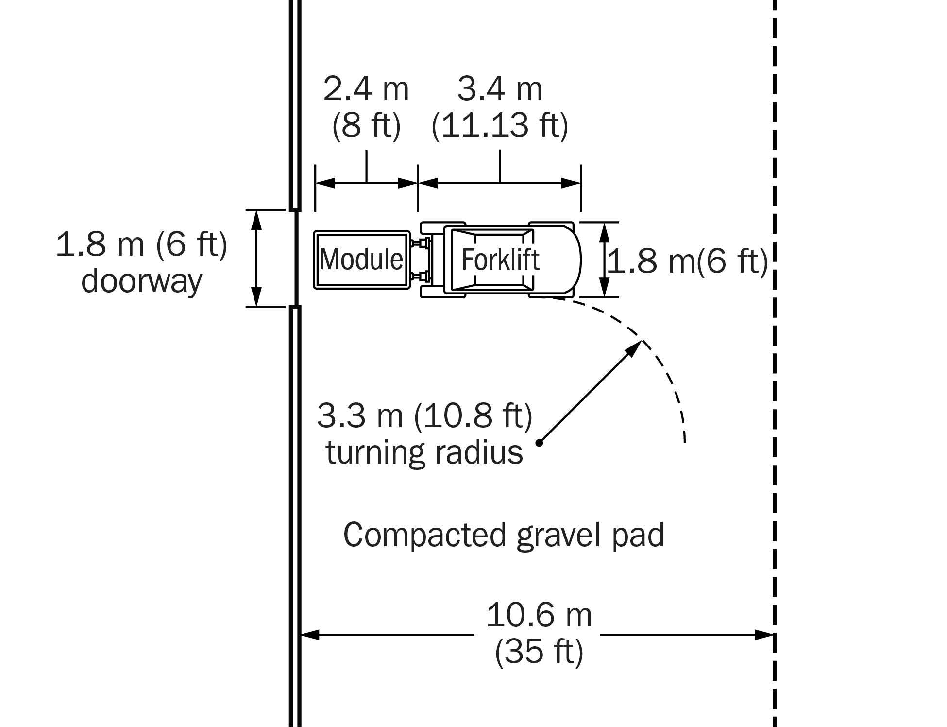
Side door loading involves the widening and upgrading of the farm laneway along one side of the broiler barn (long axis). This 10.7-m (35-ft) wide, all-season driving lane is necessary to allow the forklift or telehandler enough room to maneuver. The equipment must be able to approach the barn door in a straight line to place the module in the doorway without catching the door sides (Figure 11). This laneway will need to be maintained all year — graded to prevent pothole formation and snow removed to allow the forklift or telehandler to work in all weather conditions.
Side door loading is accomplished by removing the current loadout ramps from the outside of the barn and widening the existing main doors to a minimum 2.1 m high x 2.1 m wide (7 ft high x 7 ft wide). This allows the forklift or telehandler to place the modules into the second floor at the current 15.2‑m (50-ft) doorway intervals. The widening of the doorway may involve the relocation or modification of ventilation equipment (exhaust fans or air inlets) depending on the barn layout. Avoid installing metal trim around the bottom of the doorway as this may become damaged by forklifts during placement and retrieval of the module into the second-floor opening. Treat this doorway like a loading dock. Also consider installing curb stops at ground level to prevent the front wheels of the forklift/telehandler from coming too close to the barn and damaging the siding.
Ideally there is no door sill across the bottom of the doorways to impede the movement of the module into and out of the second-floor doorway. Otherwise, a reinforced temporary plywood pad may need to be added so the module is high enough for forklifts to access the slots on the module (Figure 12).
The second-floor structure, in the immediate vicinity of the loadout doors, should be inspected by a structural engineer. Any repairs or design upgrades must be done to support a minimum distributed live load of 4.30 KPa (90 lb/ft2). This represents the maximum loaded weight of the Meyn Maxiload twin module sitting on the floor, which is a significantly higher floor load than presently required in the National Farm Building Code, 1995, for cleanout tractor plus litter.
Other site considerations
Parking area for crew truck and forklift trailer unit
These units are considerably larger than previous crew vans for crate loading. Farms will need a maintained parking area to accommodate an additional tractor trailer unit that does not impede chicken transport trucks accessing or leaving the farm site during the loadout.
Staging area for poultry transport trucks waiting to be loaded
Transport trucks must drive onto the farm. No backing in off the road. Every farm should have a staging area for at least one transport trailer to allow the driver to release the straps and begin trailer preparation. Drivers should not be required to park on the side of the road at night for safety reasons.
Depending on building configuration, the yard/laneway area must be large enough to turn 16.2‑m (53‑ft) trailers around on the farm property so they can drive back out of the laneway when fully loaded. There should be enough room to maneuver at least two live haul trucks on the property.
Summary
The implementation of modular loading on your farm is dependent on your processing company. They will determine the proper timing and equipment selection. This factsheet explains what modifications may be necessary to your pre-existing facilities to help you understand the changes needed to use this equipment. If you are planning to build a new barn, the factsheet will also provide details that you should include in your planning to accommodate modular loading.
Resources
Business and Transition Plan: Modular Handling of Chickens in Ontario Chicken Industry. Association of Ontario Chicken Processors (2010).
This factsheet was written by Al Dam, Provincial Poultry Specialist, OMAFRA, Guelph, Daniel Ward, Structural Engineer, Poultry, OMAFRA, Stratford, and Sabrina McDonald and Amanda Bordin, Poultry Research Assistants, OMAFRA, Guelph.