Odour Control and Design of Sewer
Chapter 4: Odour Control
Sewage contains numerous potentially odourous substances, but the predominant groups are the reduced sulphur compounds. Of these, hydrogen sulphide (H2S) is perhaps the most common and easily identified.
There are several texts which discuss odour generation, particularly as related to sulphides. The designer is referred to the U.S. EPA Design Manual, Odour and Corrosion Control in Sanitary Sewage Systems and Treatment Plants (EPA/625/185/018) and the ASCE Manual of Practice No. 69 Sulfide in Wastewater Collection and Treatment Systems.
4.1 Odour Measurements and Limits
Odour measurement is largely subjective. The most commonly accepted method of characterization is the Odour Unit (OU). The OU is based on the number of dilutions with clean air required to reach a threshold detection level. OU values are presented as an odour sample’s Effective Dose - 50th percentile (ED50), meaning the number of dilutions at which an odour is detected by half the members of an odour panel using a dynamic dilution olfactometer. Thus, a sample which requires 4 dilutions to reach ED50 will contain 5 OU (4 dilutions plus the original volume).
The designer should determine, in consultation with the owner (and often the public), the appropriate odour limits and how they should be applied to the sewage works. Often a fence line odour limit is applied which determines the magnitude of the odours acceptable at the boundary of the facility. The limit will depend on the proximity of residential and commercial development and other site specific factors such as the proximity of parks, trails or roads and the sensitivity of the odour problem.
4.2 Potential Odour Sources
Odour problems tend to develop when dissolved hydrogen sulphide concentrations exceed 0.5 mg/L, or less if the pH is depressed. Production of sulphides commences in the collection system and will continue to occur wherever deposits accumulate under anaerobic conditions. The rate of sulphides production and odour generation are both temperature dependent. Industrial discharges frequently exacerbate odour. Typically, high sulphides content in discharges is most prevalent at low pH or high temperature conditions.
Turbulence promotes sulphides stripping and hence odours. In the collection system this occurs at drop manholes, sharp bends, forcemain discharge points and any hydraulic structure where turbulence or super-critical flow develops. Generally, the odour-emission potential at treatment plants decreases at each successive treatment stage. The influent sewer and headworks have a higher potential for odour emissions since they receive raw sewage with a higher sulphide content and are often turbulent areas. Preliminary treatment processes can generate odours from the screenings and grit handling areas. Aerated grit tanks will also strip sulphides.
Further sulphides generation often occurs as a result of anaerobic conditions in the sludge blankets accumulating in primary sedimentation tanks. The resultant hydrogen sulphide can be stripped at the effluent weirs due to the turbulence developed there. Aeration basins do not usually generate high sulphides odour, unless overloaded, as sulphides are oxidized within the basin. Final clarifiers rarely produce significant odours unless there are problems with the sludge or scum handling systems.
Solids handling and treatment processes have significant odour generation potential because of the high concentrations of sulphides present in sludge, scum and septage. Aerobic digesters, thickening and dewatering processes and sludge storage lagoons are all potential odour sources.
4.3 Evaluation of Odour Production Potential
4.3.1 Monitoring Protocols
Detailed monitoring should be preceded by a preliminary study to analyze available data and odour complaints. Complaints should be correlated with data on plant operations, sewage characteristics and meteorological data. The preliminary study may include limited on-site sampling and analyses. Detailed field monitoring programs should be of sufficient duration to monitor seasonal variations in sulphides generation and hydrogen sulphide emissions. Monitoring should also include an hourly sampling and testing regime to identify typical diurnal fluctuations. Sampling points should be readily identifiable and remain consistent throughout the monitoring program.
4.3.2 Liquid Phase Analyses
Routine parameters to be monitored should include total and dissolved sulphides, BOD5 or COD, temperature, pH and dissolved oxygen (DO). Oxidation-reduction potential (ORP) can also yield useful data. Additional analyses for TSS and particle size distribution will be needed if the results are to be used for predictive modelling of sulphides generation.
4.3.2.1 Gas Phase Analyses
In situ gas phase testing can be used to identify a wide range of odour producing compounds, including hydrogen sulphide, mercaptans and dimethyl disulphide. Continuous monitoring may be necessary in some cases to identify the peak hydrogen sulphide gas concentrations which trigger odour complaints. The designer should ensure that the equipment to be used for gas phase testing is suitable for the range of concentrations expected.
4.3.2.2 Air Sampling
Foul air sampling will be required if the intention is to use a dynamic dilution olfactometer and odour panel to determine OU values. Specialized sampling equipment and sample bags will be required.
4.3.2.3 Gas Chromatography
Analysis by gas chromatography (GC) is useful for identifying total levels of sulphides and other potential odour producing compounds. Analyses can be carried out on liquid or gas phase samples.
4.3.2.4 Interpretation of Results
Data obtained from monitoring programs provide the designer with useful information concerning the conditions governing sulphides generation and hydrogen sulphide release.
Areas of anaerobic activity producing sulphides are characterized by low dissolved oxygen or DO (less than 0.5 mg/L) and negative ORP. Reaction kinetics are temperature dependent. The rate of sulphides generation is greater in the presence of higher fractions of soluble BOD. Hydrogen sulphide emissions are increased at lower pH and higher temperature conditions.
4.3.3 Predictive Modelling
4.3.3.1 Sulphides Generation in Sewers and Forcemains
A number of predictive models have been developed for this purpose. The models have been developed from empirical data and are generally only valid for specific conditions. The designer is cautioned to ensure that the chosen method of analysis is applicable under the conditions in question.
4.3.3.2 Air Quality Computer Modelling
If designing to specific odour limits at identified receptor points, the designer should consider the use of a computer-based atmospheric dispersion model to simulate the behaviour of the odour plume.
4.4 Odour Control and Abatement Measures
It is generally more reliable and cost effective to treat and remove odour producing compounds in the liquid phase rather than collecting and treating foul air. Sulphides develop in the collection system and the designer should therefore consider upstream control measures in conjunction with measures at the sewage treatment plant. Such measures should include designing to prevent deposition in sewers, minimizing residence time in pump station sumps and avoiding the use of siphons and long forcemains.
4.4.1 Prevention of Sulphides Formation
For new sewage treatment works, the designer should attempt to eliminate 'dead zones' where solids may accumulate. This can include increasing atmospheric turbulence (i.e., air entrainment) and attention to collection system design. An increase in atmospheric turbulence can be produced by several mechanical means, including adding structures and/or vegetation. Vegetation can increase local air turbulence and act as a filter. Design of gravity interceptors, tunnels, forcemains, siphons, wet wells and related facilities needs to include features to minimize the generation of sulfides and other odourous compounds formed by anaerobic biological activity. The design of the collection system will have an effect on the production and release of odours. Factors to be considered are as follows:
- Pipe slope;
- Transition structures;
- Manholes;
- Proximity to receptors; and
- Inverted siphons and forcemains.
Fillets should be incorporated into rectangular channels, conduits and tanks. Inverted siphons should be avoided. Aeration should be provided to channels and conduits where self-cleaning velocities cannot be achieved over the full flow range. Excessive aeration should be avoided because of potential odour generation due to increased turbulence.
Provide sufficient energy input per unit volume to ensure solids are maintained in suspension. The designer should also consider improved access provisions to facilitate routine housekeeping and cleaning activities.
4.4.2 Chemical Treatment
When dosing chemicals into sewage, side reactions will occur in addition to the desired reaction. In calculating dosing rates, the designer should allow a generous factor of safety to account for these side reactions. Pilot-testing should be considered for chemical dosing systems to establish appropriate dosages.
4.4.2.1 Oxidizing Agents
Chlorine (in gaseous form or as sodium hypochlorite solution), potassium permanganate and hydrogen peroxide will oxidize sulphides and inhibit sulphide production. Pure oxygen and air injection have also been used to raise DO levels in sewage.
4.4.2.2 Precipitants
Iron and zinc salts will precipitate sulphides. Ferrous and ferric chloride have been used in collection systems, forcemains and at sewage treatment plants.
The designer should consider the effect on the solids handling streams at the sewage treatment plant in terms of increased sludge production, increased levels of contaminants in the sludge and any corrosion implications.
4.4.2.3 pH Control
Intermittent slug dosing with sodium hydroxide will raise the pH, inhibiting sulphide production and preventing hydrogen sulphide off-gassing. This system is effective only in localized areas and should be considered only for specific problem areas in the collection system.
4.4.2.4 Electron Acceptors
Electron acceptors are taken up preferentially to the sulphate ion and thus prevent sulphide formation. Sodium nitrate has been used in lagoons for this purpose. Proprietary nitrate products have also been used in sewers.
4.4.2.5 Anthraquinone
Anthraquinone is a chemical that inhibits bacteria from using sulfate in their metabolic processes. It is only slightly soluble and should settle into the slime layer to become effective. When contacted by anthraquinone, the bacteria in the slime layer are inactivated for a period of several days up to six weeks. After this time, the bacteria start sulphide production again if not re-treated. Because of the low solubility, it is only partially effective in forcemain applications and for fast gravity main flows.
4.4.2.6 Caustic Slug Dosing
Sodium hydroxide is a strong caustic solution. It controls hydrogen sulphide by shifting the sulphide equilibrium from the H2S form to the dissolved hydrosulfide (HS−) form. The continuous addition of sodium hydroxide would prevent the release of H2S, but is not a cost-effective solution. Periodic slug dosing with sodium hydroxide, however, can be effective in a sewer system. It works not by shifting the chemical equilibrium, but by inactivating the biological slime layer which is responsible for the generation of H2S. The slime layer will regrow, but it will take several days or weeks for it to resume full sulphide production.
4.4.2.7 Nitrate Addition
Facultative and obligate anaerobic bacteria, which are responsible for sulphide production, prefer nitrate to sulphate as an electron acceptor. This results in the production of nitrogen gas and other nitrogenous compounds rather than hydrogen sulphide. Nitrate can be obtained in a variety of liquid and dry forms, mostly as sodium or calcium nitrate. It has several advantages over other control options, since nitrate:
- Is consumed more slowly than dissolved oxygen in sewer systems;
- Is nonflammable and nonhazardous, requiring no special containment or safety provisions; and
- Produces only minor flocculants and lower solids production.
4.4.2.8 Reaeration or Oxidation
The addition of oxygen to the sewage works can decrease odours from sewage since most odours are produced under anaerobic conditions within the sewage works. The addition of oxygen can directly oxidize the odour-causing compounds or create aerobic conditions necessary for aerobic bacteria to carry out this conversion. Through metabolic processes, aerobic bacteria prevent the formation of odourous compounds by outcompeting anaerobic bacteria for available substrate in the sewage.
The addition of pure oxygen gas accomplishes the same thing as the addition of air, but only approximately one-fifth as much volume is added to achieve the same dissolved oxygen concentration. Oxygen can either be generated on-site or purchased commercially. It has the further advantage of not containing nitrogen and thus it significantly reduces the potential for air binding. It also allows treatment of forcemains with longer detention times.
Air is a readily available source of oxygen. Air injection may cause turbulence since it comprises approximately four-fifths gasses other than oxygen, which will result in the release of odourous gasses. It has proven to be successful when injected at the head of short to moderate length forcemains. Problems have been encountered in forcemains that have high points since there is the potential for air binding and reduced flow capacity.
Ozone is an extremely powerful oxidant that can oxidize H2S to elemental sulfur. Ozone is unstable and should be generated on-site. Ozone is a disinfectant. It is also toxic to humans at concentrations above 1 mg/L. Although it has been shown to reduce odours in air, effectiveness in reducing odourous compounds in sewage has not been documented. Since it is generated from air (although it can also be generated from pure oxygen), the problems associated with air injection into sewage also apply to ozone injection. Ozonation requires fairly sophisticated equipment, which is not readily utilized at unstaffed sites.
4.4.3 Control of Mass Transfer
The transfer of sulphides from liquid to gas phase can be reduced by minimizing liquid turbulence and reducing aeration. The designer should consider the following measures to reduce turbulence:
- Minimize elevation differences where streams converge;
- Introduce side streams below the liquid surface;
- Use submerged effluent weirs and downstream flow control in lieu of conventional launders for sedimentation tanks and clarifiers;
- Avoid excessive or unnecessary aeration; and
- Avoid the use of screw lift pumps on potentially odourous streams.
4.4.4 Foul Air Collection and Treatment
The following emission control systems should be considered for all solids handling areas and processes and for other areas of the facility where preventative measures are insufficient to mitigate odours.
Covers
Cover systems should be designed to minimize the number of joints. Seals should be provided at all joints. The designer should consider the corrosive action of sulphides and sulphuric acid when selecting cover materials and concrete coatings. Overhangs, ledges or lips on the underside of covers where condensate may collect should be avoided. The design of covers should be aimed at minimizing the volume of air requiring treatment.
The designer should consider operational requirements for access and cover removal and be aware that the installation of covers will create a confined space environment.
Ventilation
Ventilation rates should be based on the more stringent of two requirements:
- maintain a slight negative pressure in the headspace and thus prevent fugitive odours escaping through joints in the cover system, and
- limit sulphide concentrations in the air stream to a level that the downstream treatment systems can effectively treat.
Treatment Systems
There are numerous alternative treatment systems available. Selection of the appropriate system should be subject to a life-cycle cost-benefit analysis. The systems that may be considered include:
- Chemical scrubbers, packed bed or mist contactor types;
- Activated carbon, with or without chemical impregnation;
- Activated alumina impregnated with potassium permanganate;
- Biofilter, in-vessel or soil/compost types;
- Incineration (i.e., thermal oxidation); and
- Dual-stage systems comprising one or more of the above.
Design requirements for these systems vary considerably. The designer should consult equipment manufacturers for details.
When assessing bulk chemical storage requirements, the maximum effective storage life of the chemical should be considered. Many chemicals are temperature sensitive and storage tanks will require special provisions if located outdoors.
Provision will also be required for disposal of waste and side-streams from the treatment processes which may require further treatment before return to the main liquid train at the sewage treatment plant. An alternative form of biological treatment or pre-treatment involves blowing foul air through aeration tanks. Consideration and care should be given to potential blower corrosion and air-side diffuser fouling. For all sources of contaminants emission to the air within sewage works, the requirements of section 9 of the EPA need to be satisfied (Section 3.11 - Emissions of Contaminants to Air).
Operation and Maintenance
Reduction of the sludge storage on the treatment plant site should be considered to prevent odours if the sludge is susceptible to pH decay, in particular with unstabilized sludge. Adequate facilities should be provided for ventilation of any sludge storage or dewatering areas, if applicable. The exhaust air should be properly conditioned to avoid odour nuisance.
There are a number of operational procedures that can be utilized to limit the production or release of odours, the most important being good housekeeping. Routine hosing and debris removal at pump station wet wells and within the treatment plant can significantly reduce odour production. Operation of wet wells is also an important factor. While it may be more energy efficient to operate at higher wet well levels, this increases detention times and the potential for development of anaerobic conditions and H2S production. Fill-and-draw pump stations should consider more frequent pumping while level set-points on variable speed pump stations should be lowered where odour is an issue.
The first step in any foul air treatment system is containment of the odourous air. If fugitive emissions under normal operation are not eliminated, the entire odour control strategy is negated. This applies to covered process tanks and channels and to occupied spaces. Collection of foul air from covered tanks and channels has traditionally been based on air exchange rates. A moderate exchange rate may be required to reduce condensation and corrosion. A higher exchange rate may be needed to allow utilization of the enclosed space above a clarifier or CSO tank.
Collection of foul air for prevention of air escape through cracks, leaks and other penetrations in a cover primarily depends on establishing a negative pressure within the enclosed headspace. The negative pressure is established by exhausting air from the enclosed headspace, which draws air into the headspace through the various openings in the cover. The negative pressure is a function of the air velocity through these openings. Factors to be considered in type and location of covers are:
- Permanency (fixed, removable);
- Ease of removal (by crane, manually);
- Accessibility/visibility (hatches, clear panels);
- Aesthetics (sun reflection, camouflage); and
- Sealing (gasketed, permanently sealed).
Odour containment is only effective if it is not compromised by leaving hatches or doors open or otherwise compromising the containment. It requires an ongoing education program to ensure that odour control procedures and design intentions are maintained.
While containment will increase the difficulty associated with operating covered units, it is important that every effort be made to minimize the inconvenience and maximize worker safety. For example, hatches which need to be opened to observe internal equipment should be readily accessible and easily opened.
4.5 Separation Distances Between Sewage Works and Sensitive Land Use
The separation distances specified in ministry Guideline D-2, Compatibility between Sewage Treatment and Sensitive Land Use are intended to mitigate the effects of offensive odours which may occur during normal operations or when facilities have minor overloads or upsets created by abnormal conditions or sludge processing/handling. Compliance with Guideline D-2, by providing adequate separation distances to mitigate odours, may also provide for adequate attenuation for noise associated with plant operation.
Separation distances should be measured from the periphery of the facility structure(s) that produce odours to the property lot-line of the sensitive land use and take into account any approved expansions to either the facility or the sensitive land use. Otherwise, it should be recognized that future expansions may be limited.
When new facilities or expansion to existing facilities are proposed, an adequate buffer area should be acquired as part of the project. Where an adequate buffer area cannot be purchased or provided, more effective technical mitigation procedures would be necessary to provide an optimum level of protection between the sewage treatment facility and affected sensitive land uses. The designer should consider covering certain sections of the facility and treating collected off-gases. In some cases a combination of distance, covering and treatment of collected off-gases may be required.
Recommended separation distances for sewage treatment plants (STP) in proportion to their rated capacities are provided in subsequent sections.
4.5.1 STP with Rated Capacity Equal to or Less than 500 m3/d (0.13 mUSgd)
For STP with a rated capacity of less than 500 m3/d (0.13 mUSgd), the recommended separation distance is 100 m (330 ft). A separation distance of less than 100 m (330 ft) may be acceptable, however a qualified professional would be required to produce a study demonstrating the suitability of the distance based on:
- The degree and type of odour mitigation applied to the facility;
- Other contaminants of concern (i.e., aerosols) which may need to be addressed; and
- The application of noise reduction equipment to any potential noise source(s).
4.5.2 STP with Rated Capacity Greater than 500 m3/d (0.13 mUSgd) but Less than 25,000 m3/d (6.6 mUSgd)
The recommended separation distance is 150 m (490 ft) with the minimum separation distance of not less than 100 m (330 ft).
4.5.3 STP with Rated Capacity Equal to or Greater than 25,000 m3/d (6.6 mUSgd)
The recommended separation distance should be greater than 150 m (490 ft) and determined on a case-by-case basis. The determination of the required distance will depend on factors such as the type of treatment process, type of noise or odour control measures being applied, existing municipal zoning and availability of land.
4.5.4 Sewage Lagoons
Notwithstanding sewage treatment plant requirements, the recommended separation distance for lagoons varies from 100 to 400 m (330 to 1,300 ft). A suitable separation distance should be determined by a qualified consultant on a case-by-case basis. In determining a suitable separation distance, considerations may include factors such as lagoon design, hauled sewage or sludge handling and whether there is a supplemental aeration system. Odours and the aerosols emitted from the lagoons are also dependant upon the operation, design, environmental conditions and the season in some cases.
Chapter 5: Design of Sewers
This chapter describes design guidelines associated with the collection and transport of sewage and stormwater. The items described in this chapter include storm sewers and sanitary sewers, as well as alternative sewer types, sewer system rehabilitation, manholes, pipe design and inverted siphons. A section is included on sewers with streams and aerial crossings and protection of drinking water supplies.
5.1 Introduction
These design guidelines are intended to assist consulting and municipal engineers and other designers in the preparation of sewer system designs. Municipalities, in which the sewage works will be constructed, may have servicing standards that exceed the requirements of these guidelines. The designer should ensure that they are aware of the requirements of all other approving authorities prior to finalizing any designs.
Although some aspects of the guidelines relate only to municipal services, the guidelines are meant to apply to other sewer systems serving developments such as mobile home parks and condominiums which also require ministry approval under the Ontario Water Resources Act (OWRA) (Section 1.5 - Ministry Approval Program for Sewage Works).
5.2 Separate Versus Combined Sewers
All new sewer construction in Ontario should be of the separate type, with stormwater and groundwater flow being excluded to the maximum possible extent. Stormwater and groundwater flow consist of rain, water from roofs, streets and other areas and groundwater from foundation drains.
A combined sewer system is a collection system designed to convey both sanitary sewage and stormwater runoff through a single-pipe system to a sewage treatment works. See Section 8.3.4 Combined Sewer System for additional related information.
New combined sewer systems will not be approved by the ministry. New storm drainage systems will not be permitted to connect to existing combined sewers except as an interim measure where circumstances allow no other alternative. In such cases, the proponents will be required to provide the justification for the continued use of combined sewers along with a plan and a timetable for the ultimate disposition of the storm drainage. The designer should refer to Chapter 21 - Control and Treatment of Combined Sewer Overflows for information on combined sewer overflow treatment needs.
Since the ministry discourages the extension of combined sewers, the design of such systems is excluded from this document.
5.3 Stormwater Management
Stormwater management is required to mitigate the effects of urbanization on the hydrologic cycle including increased runoff and decreased infiltration of rain and snowmelt. The ministry’s Stormwater Management Planning and Design Manual (2003) provides guidance for planning and designing stormwater management systems to meet the multiple objectives of stormwater management: maintaining the hydrologic cycle, protection of water quality and preventing increased erosion and flooding.
The designer should refer to the Stormwater Management Planning and Design Manual (2003) for design guidance for individual lot level, conveyance, and end-of-pipe practices. The manual includes physical constraints such as, soil type and depth to groundwater, as well as sizing and configuration and design details including inlets and outlets, filter media and distribution pipes. The guidance also includes cold climate considerations and the incorporation of vegetation in system design.
For additional information the designer should refer to Section 21.3 - Source Management and Control Technologies.
5.4 Storm Sewers
The following subsections cover flow calculations pertaining to the design of separate storm sewer systems.
5.4.1 Runoff Computation
The peak rate of runoff from an area may be calculated using the Rational Method, using the following formula:
Q = 2.78 C × i × A
Where:
- Q
- Peak flow (L/s)
- A
- Area in hectares
- i
- Average rainfall intensity in millimetres per hour for a duration equal to the time of concentration for a particular storm frequency. The time of concentration is the time required for stormwater runoff to flow from the most remote point of a watershed or drainage area to the outlet or point under consideration.
- C
- Runoff coefficient; see Table 5-1 for typical values
This formula is used for sizing storm sewers to remove water as fast as possible from street surfaces for the specific design storm frequency. When the calculation of the volume of runoff or the rate over time (hydrograph) is needed, then a hydrologic simulation model will be necessary.
Calculations based on a hydrologic simulation model are preferable. For systems serving large areas, or involving treatment and/or storage systems, the use of a model may be necessary.
The remainder of this section will deal only with the Rational Method. Reference should also be made to the Ministry of Transportation and Communication (MTC) Drainage Manual (1980), for a further discussion of the Rational Method for storm sewer design. This MTC Manual also covers culvert and open channel design guidelines.
5.4.2 Drainage Area
The drainage area to be used in the design of a storm sewer system should include all those areas which will reasonably or naturally drain to the system.
The area term in the Rational Method formula represents the total area tributary to the point on the storm sewer system under consideration.
5.4.3 Rainfall Intensity
The rainfall intensity for a specific storm frequency and time of concentration should be determined from intensity duration - frequency curves applicable for the municipality in which the system is to be constructed.
For a discussion of rainfall intensity curves, reference should be made to The Urban Drainage Subcommittee of the Canada-Ontario Agreement on Great Lakes Water Quality Manual of Practice on Urban Drainage (1987) and Ministry of the Environment and the Municipal Engineers Association Municipal Works Design Manual (1984).
5.4.4 Design Storm Frequency and Runoff Coefficient
The storm frequency in the design of stormwater conveyance systems will vary depending upon the nature of the area being served, the value of the property being protected and the consequences of more intense storms being experienced.
It is recommended that the major-minor drainage system approach be utilized for urban drainage for all future development. The minor drainage system (i.e., roof gutters, service connections, street gutters, catch basins and storm sewers) accommodates the runoff from more frequent storms up to the design frequency of the system (e.g. 2-year return design storm). Where weepers/foundation drains are connected to the storm sewers, they should also be designed to capture no more than the amount of runoff from design frequency storm in order to prevent surcharge conditions.
The major system (i.e., natural streams and valleys and the roads, swales, channels and ponds) accommodates runoff from less frequent design storms such as the 100-year return design storm or regional flood event.
Although the designer should consult the local weather data to establish the design storm frequency criteria for the design of stormwater conveyance systems, the level of convenience provided by the minor system is a decision of the municipality, or the owner of the system in the case of private systems. It is recommended that as a minimum a 2-year return design storm should be used for design purposes. For information on design details of major-minor systems the designer should refer to the ministry document Stormwater Management Planning and Design Manual (2003).
The following ranges of runoff coefficients shown in Table 5.1 are considered reasonable for design purposes:
| Sources | Coefficient (C) |
|---|---|
| Asphalt, concrete, roof areas | 0.90-1.00 |
| Grassed areas, parkland | 0.15-0.35 |
| Commercial | 0.75-0.85 |
| Industrial | 0.65-0.75 |
| Residential Single Family | 0.40-0.45 |
| Residential Semi-detached | 0.45-0.60 |
| Residential Row housing, Townhouses | 0.50-0.70 |
| Residential Apartments | 0.60-0.75 |
| Institutional Residence | 0.40-0.75 |
The runoff coefficient for any particular type of area should the upper value of the above tabulated ranges to account for antecedent precipitation conditions when expected runoff is being calculated for less frequent, high intensity storms. The lower value of the range may be used for shorter recurrence interval storms under conditions of moderate to flat slopes and permeable soils.
The time of concentration is the time required for flow to reach a particular point in the sewer system from the most remote part of the drainage area. It includes not only the travel time in the sewers, but also the inlet time or time required to flow overland into the sewer system.
Inlet times should be calculated rather than relying upon arbitrary minimum or maximum times. The calculation should be based upon the overland flow route that will exist when the sewer system has been fully developed to the drainage limit. In the case of single-family residential areas, calculations will not be needed if a maximum inlet time of 10 minutes is used. Sewers should be designed with the ability to overflow to avoid emergency and/or unavoidable conditions. For details on such conditions refer to Section 8.3 Definition of Terms.
5.4.5 Catch Basins
Catch basins may be installed with or without sumps. The minimum pipe size for a single catch basin lead should be 200 mm (nominal pipe size of 8 in; NPS-8) in diameter and 250 mm (NPS-10) for a double catch basin.
Catch basins should be provided at adequate intervals in the sewer system to ensure that the road drainage is able to be intercepted up to the capacity of the storm sewer. The spacing will vary with the road width, grade and crossfall and with the design storm frequency. The spacing will also be affected by the location of pedestrian crossing points, intersections, low points and driveway depressions. In general, for pavement widths up to 9.8 m (32 ft) with two per cent crossfall, the maximum spacing that should be used is shown in Table 5.2.
| Road Gradient (%) | Maximum Spacing |
|---|---|
| 0 to 3 | 110 m (350 ft) |
| 3.1 to 4.5 | 90 m (300 ft) |
| Over 4.5 | 75 m (250 ft) |
Stormwater management systems using inlet control catch basins may be designed with less frequent spacing than those outlined above. In such cases, the designers should justify whatever spacing is used.
5.4.6 Storm Sewer Gratings
The inlets and outlets of piped sections of stormwater management systems which are accessible to the public should be provided with protective devices. As a minimum, it is recommended that inlets and outlets of pipes 600 mm diameter (NPS-24), or larger, should be provided with gratings to prevent small children from gaining access to the sewers. Grating bars should be spaced 150 mm (6 in) apart. For large inlet structures, inclined gratings may be necessary to prevent water pressure from trapping a person against the grating. Such inclines will also tend to make the gratings self-cleaning from a debris standpoint.
5.4.7 Foundation Drainage
It is recommended that foundation drainage be directed either to the surface of the ground or storm sewer system, if one exists.
The designer should consider and advise the municipality of the following factors:
- Possibility of storm sewer surcharging;
- Difference in elevation between basement floor slabs and storm sewer obverts;
- Possibility of foundation damage and flooding which could result due to back up into private storm drains;
- Where concerns exist regarding the first two points, but where connection to a storm sewer is still desirable, this connection should be made via a sump pump system; and
- The use of a “third” pipe or foundation drain collector.
Where foundation drains are to be connected by gravity to the storm sewers, the designer should consider the following options in order to reduce the probability/frequency of foundation drain surcharging:
- The use of a higher return frequency in the design of the storm sewer;
- The construction of a deeper sewer with the depth of the sewer being determined/checked by the hydraulic grade line for surcharged conditions; and
- Inlet controls or increased spacing of the inlets to prevent water from gaining access to sewers at a rate greater than the design storm event.
The designer should recognize that the state-of-the-art of inlet control design has not reached the point where performance can be guaranteed.
Foundation drains for industrial, commercial and institutional buildings should not be directed to sanitary sewers.
The connection of the foundation drains to a sanitary sewer system is strongly discouraged by the ministry because of the serious negative impact such connections might have on the system and the operation of the sewage treatment plant.
5.4.8 Storm Sewer Design
It is recommended that storm sewer capacities be calculated using the Manning formula with a roughness coefficient (n) of 0.013 for all smooth-walled pipe materials (Section 5.7.1 - Flow formulas and Roughness Coefficient). With corrugated metal pipe, the roughness coefficient “n” should be 0.024 for plain pipe, 0.020 for paved invert pipe and 0.013 for fully paved pipe.
For a more complete discussion on manhole spacing, hydraulics, pipe design, depth of cover and pipe anchoring the designer should refer to Section 5.7.1 - Details of Design and Construction of Sewers.
5.5 Sanitary Sewers
5.5.1 Design Period and Tributary Area
Wherever possible, the design of sanitary sewers should be based on the ultimate sewage flows expected from the tributary area. Tributary areas need not necessarily be restricted to current municipal limits. In cases where the tributary area is poorly defined, or where the financial burden on present users would be too severe, the sewage system design may be based on more restricted approaches. In these cases the design period should be at least 20 years.
For the estimation of future sewage flow rates for municipal sewage collection systems, the designer should make reference to the Official Plan (or Draft Official Plan) of the municipality. Such official plans will contain future population densities and land uses.
If no official plan or draft plan exist, the designer should size sanitary sewers for population densities of at least 25 persons per gross hectare. This minimum level of population density will generally be suitable for rural municipalities only. If the municipality already has higher population densities, the designer should use similar or higher densities for new growth areas.
Sanitary sewer capacities should be designed for the estimated ultimate tributary population, except where parts of the systems can be readily increased in capacity. Similarly, consideration should be given to the maximum anticipated capacity of institutions, industrial parks and other sewage sources. For details on design flows refer to Section 8.5.4 - Sewage flows.
5.5.2 Design Sewage Flows
Sanitary sewage flows are made up of wastewater discharges from residential, commercial, institutional and industrial establishments, plus extraneous flow components from such sources as groundwater and surface runoff.
The peak sewage flow rates, for which sewer system capacity is to be provided, should be calculated for all flow contributors, for present and future conditions. In addition to being able to carry the peak flows, sewers should be able to develop sufficient flow velocity to transport the sewage solids, thus avoiding deposition and the development of nuisance conditions under lesser flow rates.
5.5.2.1 Domestic Sewage Flows
The following criteria should be used in determining peak sewage flows for municipal sewer design for residential areas:
- Design population derived from drainage area and expected maximum population over the design period;
- Average daily domestic flow (exclusive of extraneous flows) of 225 to 450 L/(cap·d) [59 to 119 US gal/(cap·d)];
- Peak Extraneous Flow; and
- Peak domestic sewage flows to be calculated using the following formula:
Q(d) = (PqM ⁄ 86.4) + IA
Where:
- Q (d)
- Peak domestic sewage flow (including extraneous flows) in L/s
- P
- Design population, in thousands
- q
- Average daily per capita domestic flow in L/cap·d (exclusive of extraneous flows)
- I
- Unit of peak extraneous flow, in L/(ha·s); applicable references should be consulted for values
- A
- Gross tributary area in hectares
- M
- Peaking factor (as determined from Harmon or Babbitt Formula)
Harmon Formula
M = 1 + (14 ⁄ 4 + P0.5)
Babbitt Formula
M = (5 ⁄ P0.2)
Note that the minimum permissible peaking factor M is 2.0.
5.5.2.2 Commercial and Institutional Sewage Flows
The sewage flows from commercial and institutional establishments vary greatly with the type of water-using facilities present in the development, the population at the facilities, the presence of water metering and the extent of extraneous flows entering the sewers.
Institutional flows should be computed for each individual case based on historical records, when available. Where no records are available, the unit values in Table 5-3 should be used. For commercial and tourist areas, a minimum allowance of 28 m3/(ha·d) [2,993 US gal/(ac·d)] average flow should be used in the absence of reliable flow data.
For individual commercial and institutional uses the sewage flow rates shown in Table 5-3 are commonly used for design.
The peaking factors applicable for sewage flows from individual establishments will be similar to the relative peak water usage rates. The designer should refer to the ministry Design Guidelines for Drinking Water Systems for details.
| Use | Unit Sewage Flow1 SI (L/d) |
Unit Sewage Flow1 US (US gal/d) |
Flow Unit per |
|---|---|---|---|
| Shopping Centre | 2.5-5.0 | 0.7-1.3 | based on total floor area (m2 and ft2) |
| Hospitals | 900-1800 | 237-475 | bed |
| Schools | 70-140 | 18.5-37 | student |
| Travel Trailer Parks | 340 | 90 | space (min. without water hook-ups) |
| Travel Trailer Parks | 800 | 211 | space (min. with indiv. water hook-ups) |
| Campgrounds | 225-570 | 59-150 | campsite |
| Mobile Home Parks | 1000 | 264 | parking space |
| Motels | 150-200 | 40-53 | bed space |
| Hotels | 225 | 59 | bed space |
1 Unit sewage flow rates exclusive of extraneous flows.
5.5.2.3 Industrial Sewage Flows
Peak sewage flow rates from industrial areas vary greatly with the extent of area development, the types of industries present, the provision of in-plant effluent treatment and recycle/re-use or rate of flow controls, the presence of cooling waters in the discharge and other factors. Due to the occasional presence of individual industrial water supplies, the rates of water supply from municipal systems into industrial areas will not always be indicative of the sanitary sewage flows to be expected. The discharge of cooling water from municipal supplies into storm sewers or surface water courses may result in lower flows in sanitary sewers than would be expected based on municipal water usage.
The calculation of design average and peak sewage flow rates for industrial areas is industry/process specific and may be difficult to predict accurately. Improving flow prediction may include better monitoring of industries present in industrial areas. In this way, a reasonable allowance can be made for peak industrial sewage flows for an area and by flow monitoring allowances can be better maintained. Industries with the potential to discharge sewage at higher than the accepted rates may be required to provide flow equalization with discharge at off-peak discharge periods.
5.5.2.4 Foundation Drainage
It is essential that foundation drainage be directed to storm sewer systems or in accordance with local municipal best management practices taking into account on-site drainage/infiltration conditions. Since sanitary sewers are not designed to accept these flows (i.e., rainwater leaders and/or foundation drains), serious damage/problems may result, such as cracking of basement floor slabs or flooding of basements if foundation drainage is discharged to the sanitary sewers (Section 5.4.7 - Foundation Drainage).
5.5.2.5 Extraneous Sewage Flows
When designing a sanitary sewer system, an allowance should be made for the leakage of groundwater into the sewers and building sewer connections (infiltration) and for other extraneous water entering the sewers from sources such as manhole covers (inflow).
Due to the extremely high peak flows that can result from roof downspouts, they should not, under any circumstance, be connected directly or indirectly via foundation drains to sanitary sewers.
The amount of groundwater leakage into the sewer system will vary with the quality of construction, type of joints, ground conditions and level of groundwater in relation to pipe. Although such infiltration can be reduced by proper design, construction and maintenance, it cannot be completely eliminated and an allowance should be made in the design sewage flows to cover this flow component. Despite the fact that these allowances are generally referred to as infiltration allowances, they are intended to cover the peak extraneous flows from all sources (i.e., infiltration and inflow) likely to contribute non-waste flows to the sewer system.
5.6 Odours and Corrosion In Sewers
Sewers are designed to accommodate future population growth and high flow events. As a result, during low flow periods, either early in the design life of the sewer or during dry weather periods (or both), sewage velocities are reduced and solids deposition and stagnation conditions can occur. Solids deposition and slime growth can lead to anaerobic conditions and the generation of inorganic gases including hydrogen sulphide (H2S), ammonia and carbon dioxide. H2S is the most common corrosive and odorous gas produced in sanitary sewers. Once released to the sewer atmosphere, anaerobic bacteria which reside in sewer wall slimes convert the H2S to sulphurous and sulphuric acid which corrodes concrete sewer walls.
A number of factors affect H2S production in a sewer system including: settleable solids, organic material, nutrients, sulphates, dissolved oxygen, temperature, flow turbulence, velocity, surface area and detention time.
The designer should evaluate areas or portions of the sewer that promote either gas generation or ventilation. Air is normally drawn down sanitary sewers by the flow of sewage. There is also an exchange of air in the headspace as a result of an increase or decrease in flow. As the flow rate increases, the headspace air is exhausted through openings in the system, such as manhole cover openings or grating. As the flow decreases, air is drawn into the headspace in the sewer. Inverted siphons also provide a potential for gas generation due to the stagnant volume of sewage that is maintained in these pipes. This can be managed with multiple barrels and self-cleaning velocities.
Designers should recognize the potential for anaerobic conditions and gas generation in sewers and design with self-cleansing velocities, as well as provision for regular maintenance and flushing. Dissolved sulphides can be controlled by liquid-phase treatment methods such as oxygenation, chemical oxidants, precipitation, pH stabilization and nitrate addition. Once gas is released to the headspace, it needs to be collected and treated using gas phase treatment methods.
The designer should refer to Chapter 4 - Odour Control for more information.
5.7 Details of Design and Construction of Sewers
5.7.1 Flow Formulas and Roughness Coefficient
It is recommended that sanitary sewers be designed using either the Chézy-Kutter or Chézy-Manning formula and a roughness coefficient (n) of no lower than 0.013 for all smooth-walled pipe materials.
The Chézy-Manning formula, which is the most commonly used formula for calculating sewer capacity, is as follows:
Q = (1 ⁄ n) × A × R2⁄3 × S½
Where:
- Q
- Flow capacity of sewer (m3/s)
- R
- Hydraulic radius of pipe (m)
- S
- Sewer slope (m/m)
- n
- Manning roughness coefficient (unitless)
- A
- Area (m2)
For sewers with less than 900 mm diameter (NPS-36)), Chézy-Kutter’s formula gives a more conservative estimate of sewer capacity. For this reason, the Chézy-Kutter’s formula is usually used to calculate minimum acceptable sewer slopes (5.7.5 - Slope).
5.7.2 Minimum Size
No gravity sewer conveying raw sewage within a municipal sanitary sewer system should be less than 200 mm diameter (NPS-8). The minimum storm sewer diameter is 250 mm (NPS-10). Individual service connections as small as 100 mm diameter (NPS-4) may be considered by the designer.
5.7.3 Depth
Sewers should be sufficiently deep to receive sewage from basements and to prevent freezing and damage due to frost. Insulation should be provided for sewers that cannot be placed at a depth sufficient to prevent freezing.
For buildings substantially below street level, it may be more economical to pump into the sewer rather than deepen the sewer to accommodate a limited number of low-lying properties. To allow for gravity drainage from basements, sewer inverts should normally be at least 0.9 to 1.5 m (3 to 5 ft) below basement floor levels.
Reference should be made to Chapter 6 - Challenging Conditions Affecting Servicing for a recommended approach in calculating frost penetration depths.
Other factors which can affect sewer depth are interference with other utilities at crossings (both main sewer and building sewer vertical alignments can be affected by storm sewers, watermains and gas mains) and length of building sewer connections.
5.7.4 Buoyancy
Buoyancy of sewers should be considered and flotation of pipes should be prevented with appropriate construction where high groundwater conditions are anticipated.
5.7.5 Slope
All sewers should be designed and constructed to give mean velocities, when flowing full, of not less than 0.6 m/s (2.0 ft/s), based on the Chézy-Manning formula using an n value of 0.013. The Kutter formula can also be used. Table 5-4 provides the recommended minimum slopes which should be provided for sewers 1050 mm in diameter (NPS-42) or less; however, slopes greater than these values may be desirable to control sewer gases or to maintain self-cleansing velocities at all rates of flow within the design limits. The Kutter or Chézy’s roughness coefficient is used in the Chézy-Kutter and is related to the Manning roughness coefficient n by the formula below.

and
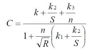
Where:
- A
- pipe cross-sectional area (m2 (ft2))
- C
- Chézy’s (or Kutter) roughness coefficient (m1/2/s, (ft1/2/s))
- S
- Friction slope (m/m, (ft/ft))
- R
- Hydraulic roughness (unitless)
- N
- Kutter’s roughness (unitless)
- k1
- Constant (23.0 SI, 41.65 US)
- k2
- Constant (0.00155 SI, 0.00281 US)
- k3
- Constant (1.0 SI, 1.811 US)
Sewers 1200 mm in diameter (NPS-48) or larger should be designed and constructed to give mean velocities, when flowing full, of not less than 0.9 m/s (3.0 ft/s), based on the Chezy-Manning formula using an n value of 0.013.
5.7.5.1 Allowances for Hydraulic Losses at Sewer Manholes
The following minimum allowances should be made for hydraulic losses incurred at sewer manholes:
| Manhole Type | Loss Incurred |
|---|---|
| Straight Run | Grade of Sewer |
| 45° Turn | 0.03 m (1.2 in) |
| 90° Turn | 0.06 m (2.4 in) |
| Junctions and Transitions | Physical modeling recommended |
Although the needed invert drops for the above hydraulic losses will be adequate for sewers with flows at the low end of the acceptable velocity range, the required drops should be specifically calculated for high velocity sewers.
5.7.5.2 Minimum Flow Depths
Slopes less than those required for a 0.6 m/s (2.0 ft/s) velocity when flowing full may be considered when increasing the slope would require deepening of extensive sections of the system or the addition of a pumping station. In such instances, the reduction of the slope would only apply to 200 mm (NPS-8) and 250 mm (NPS-10) diameter pipes, with the minimum allowable slope being 0.28% for 200 mm (NPS-8) pipe and 0.22% for 250 mm (NPS-10) pipe. Such decreased slopes may be considered where the depth of flow will be 0.3 of the diameter or greater for design average daily flow.
5.7.5.3 Solids Deposition
The pipe diameter and slope should be selected to obtain the greatest practical velocities to minimize solids settling problems. Oversized sewers should not be used to justify using flatter slopes. If the proposed slope is less than the minimum slope of the smallest pipe which can accommodate the design peak hourly flow, the actual depths and velocities at minimum, average and design peak day and design peak hourly flow for each section of the sewer should be calculated by the designer.
| Nominal Sewer Size | Minimum Slope in m/100 m (Feet per 100 Feet)1 |
|---|---|
| 200 mm (8 inch) (NPS-8) | 0.40 |
| 250 mm (10 inch) (NPS-10) | 0.28 |
| 300 mm (12 inch) (NPS-12) | 0.22 |
| 350 mm (14 inch) (NPS-14) | 0.17 |
| 375 mm (15 inch) (NPS-15) | 0.15 |
| 400 mm (16 inch) (NPS-16) | 0.14 |
| 450 mm (18 inch) (NPS-18) | 0.12 |
| 525 mm (21 inch) (NPS-21) | 0.10 |
| 600 mm (24 inch) (NPS-24) | 0.08 |
| 675 mm (27 inch) (NPS-27) | 0.067 |
| 750 mm (30 inch) (NPS-30) | 0.058 |
| 825 mm (33 inch) (NPS-33) | 0.052 |
| 900 mm (36 inch) (NPS-36) | 0.046 |
| 975 mm (39 inch) (NPS-39) | 0.041 |
| 1050 mm (42 inch) (NPS-42) | 0.037 |
1 These minimum slope recommendations should be consistent with local municipal design requirements.
5.7.6 Maximum and Minimum Velocities
All sewers should be designed with such slopes that they will have a minimum sewage flow velocity, when flowing full, of at least 0.6 m/s (2.0 ft/s). In cases where the flow depth in the sewer, under peak flow, will not be 0.3 of the pipe diameter or greater, the actual flow velocity at peak flow should be calculated using a hydraulic elements chart and the slope increased to achieve adequate flushing velocities. In certain circumstances, such as where increased slopes would require deepening of extensive sections of the sewage collection system or the addition of a pumping station, peak sewage flow velocities of less than 0.6 m/s (2.0 ft/s) may be considered provided that the municipality accepts that there may be increased maintenance requirements.
It should be noted that sewers achieving flow velocities less than those required for self-cleansing of grit and organics may have increased maintenance expenses and need frequent cleaning due to the deposition of solids. These increased maintenance costs should be compared with the costs which would have been incurred if sewers were deepened to achieve adequate slopes.
In sizing sanitary sewers and selecting sewer slopes, consideration should be given to possible sulphide generation problems. Sulphide problems can be minimized by designing for sewers to flow less than full under peak flow conditions and to flow at velocities of 0.6 m/s (2.0 ft/s) or higher.
The velocities in sanitary sewer systems should not be more than 3 m/s (10 ft/s), especially where high grit loads are expected. Higher velocities should be avoided unless special precautions are taken. Where velocities greater than 4.6 m/s (15 ft/s) are attained, special provision should be made to protect against pipe displacement by impact and erosion. Velocities in storm sewers should not be greater than 6 m/s (20 ft/s).
5.7.6.1 Steep Slope Protection
Sewers on 20 percent slopes or greater should be anchored securely with concrete anchors spaced as follows:
- Not over 11 m (36 ft) centre to centre on grades 20 percent and up to 35 percent;
- Not over 7.3 m (24 ft) centre to centre on grades 35 percent and up to 50 percent; and
- Not over 4.9 m (16 ft) centre to centre on grades 50 percent and over.
5.7.7 Alignment
In general, sewers equal to or less than 600 mm diameter (NPS-24) should be laid with straight alignment between manholes. Straight alignment should be checked by either using a laser beam or lamping.
Curvilinear alignment of sewers larger than 600 mm in diameter (NPS-24) may be considered on a case-by-case basis provided compression joints are specified and American Society for Testing and Materials (ASTM) or specific pipe manufacturers' maximum allowable pipe joint deflection limits are not exceeded. Curvilinear sewers should be limited to simple curves which start and end at manholes. When curvilinear sewers are proposed, the recommended minimum slopes indicated in Table 5-4 should be increased accordingly to provide a minimum velocity of 0.6 m/s (2.0 ft/s) when flowing full.
Sanitary sewers are generally located at or near the centreline of roads to allow buildings on both sides of the street to be serviced with approximately the same lengths of building sewers. Municipalities generally have standards on the preferred location of services. These standards should be compared with the ministry Guideline F-6, Sewer and Watermain Installation: Separation Distance Requirements.
5.7.8 Changes in Pipe Size
When a smaller sewer joins a large one, the invert of the larger sewer should be lowered sufficiently to maintain the same energy gradient. An approximate method for securing these results is to place the 0.8 depth point of both sewers at the same elevation.
Sewer extensions should be designed for projected flows even when the diameter of the receiving sewer is less than the diameter of the proposed extension. The connection should be done at a manhole constructed with an appropriate flow channel to minimize turbulence.
5.7.9 Pipe Materials
The pipe material selected should be adapted to local conditions, such as:
- Character of industrial wastes;
- Possibility of septicity;
- Soil characteristics;
- Exceptionally heavy external loadings;
- Abrasion; and
- Corrosion.
Sewers should be designed to prevent damage from superimposed live, dead and frost induced loads. Proper allowance for loads on the sewer should be made for soil type, groundwater conditions, as well as the width and depth of the trench. Where necessary, special bedding, haunching and initial backfill, concrete cradle, or other special construction should be used to withstand potential superimposed loading or loss of trench wall stability. The designer should refer to the Ontario Provincial Standards for Roads and Public Works (OPS) for details on sewer pipe materials and installation.
Suitable couplings complying with ASTM specifications should be used for joining dissimilar materials.
For new pipe materials, for which ASTM standards have not been established, the design engineer should provide complete pipe specifications and installation specifications developed on the basis of criteria adequately documented and certified in writing by the pipe manufacturer.
For sewer applications requiring pressure pipe, the designer should refer to Section 5.14 Protection of Drinking Water Systems.
In choosing pipe material, the designer should consider the following factors:
- Life expectancy and use experience;
- Resistance to scour;
- Resistance to acids, alkalis, gasses and solvents;
- Ease of handling and installation;
- Physical strength;
- Type of joint - water tightness and ease of assembly;
- Availability and ease of installation of fittings and connections;
- Availability in sizes required; and
- Cost of materials, handling and installation.
5.7.10 Installation
Installation specifications should contain appropriate requirements based on the criteria and standards established by industry in its technical publications. Requirements should be set forth in the specifications for the pipe and methods of bedding and backfilling thereof so as not to damage the pipe or its joints, impede cleaning operations and future tapping, nor create excessive side fill pressures and ovalation of the pipe, nor seriously impair flow capacity.
Excavation for placing sewer pipes, backfilling and compacting should be specified in accordance with Ontario Provincial Standards Specifications (OPSS) 514, Construction Specifications for Trenching, Backfilling and Compacting. Final backfill should be placed in such a manner as not to disturb the alignment of the pipe.
Ring deflection testing should be performed on all sewers constructed using plastic pipe. The designer should reference OPSS 410, Construction Specifications for Pipe Sewer Installation in Open Cut for details on the testing procedure.
5.7.11 Joints and Infiltration
5.7.11.1 Joints
The types of joints and the materials used should be included in the specifications. Sewer joints should be designed to minimize infiltration and to prevent the entrance of roots throughout the life of the system.
5.7.11.2 Service Connections
Service connections to the main sewer should be made using factory made tees or wyes, strap-on-saddles or other approved saddles. Factory made tees or wyes should be used for all service connections where the diameter of the main pipe sewer is:
- Less than 450 mm (NPS-18); or
- Less than twice the diameter of the service connection.
Strap-on-saddles should be installed before laying the pipe.
Holes in the main sewer pipe should be cut with approved cutters and should be the minimum diameter required to accept the service connection saddle. If mortar-on saddles are used, the inside of the pipe should be mortared at the connection. Service connections should be plugged at the property line with watertight caps or plugs. Plugs or caps should be braced sufficiently to withstand hydrostatic or air test pressures.
The designer of sanitary sewer service connections should consider:
- Minimum Diameter: For gravity flow, 100 mm (NPS-4) or pipe size needed to satisfy requirement of the Part 7 of Division B of the Building Code (Ontario Regulation 350/06) made under the Building Code Act, 1992;
- Sanitary Sewer Service Connection Grades;
- Recommended Grade 2%; and
- Minimum Grade 1%;
- Materials: Reference should be made to the Ontario Provincial Standards - OPSS 410 for acceptable alternate materials for services; and
- Risers: Service risers from main sewers buried more than 4.0 m (13 ft) should be taken off at an angle not less than 45° from the vertical, moved to the vertical by an appropriate elbow and the vertical section provided with a slide fitting. Alternatively, where the main sewer depth is greater than 4.0 m (13 ft), the use of a shallow “local” collector sewer could be considered with service connections made to the shallow sewer. The designer should consult the municipality for local design requirements.
5.7.11.3 Leakage Tests
Leakage tests should be specified. This may include appropriate water or low pressure air testing. The testing methods selected should take into consideration the range in groundwater elevations during the test and anticipated during the design life of the sewer.
5.7.11.4 Water (Hydrostatic) Test
The test section should be slowly filled with water making sure that all air is removed from the line. A period of 24 hours for absorption should be allowed before starting the test except if exfiltration requirements are met by a test carried out during the absorption period.
Water should be added to the pipeline prior to testing until there is a head in the upstream manhole hole of 600 mm (NPS-24) minimum over the crown of the pipe or at least 600 mm (24 in) above the existing groundwater level, whichever is greater. The maximum limit of the net internal head on the line is 8 m (26 ft). In calculating net internal head, allowance for groundwater head, if any, should be made.
The distance from the manhole frame to the surface of the water should be measured. After allowing the water to stand for one hour, the distance from the frame to the surface of the water should again be measured. The leakage should be calculated using volumes.
The leakage at the end of the test period should not exceed the maximum allowable calculated for the test section. In accordance with OPSS 410 allowable leakage is calculated as 0.075 L/mm diameter ⁄ 100 metres of sewer pipe ⁄ hr (8.1 US gal/inch diameter ⁄ mile of sewer pipe ⁄ hr).
An allowance of 3.0 liters per hour per metre of head (0.24 US gal/hr/ft of head) above the invert for each manhole included in the test section should be made.
Manhole should be tested separately if the test section fails.
5.7.12 Design Calculations
A tabular form may be used for recording sewer design calculations including required capacity, sewer size, sewer slope, roughness coefficient used, pipe capacity provided, flow velocity when flowing full, depth of flow, and actual flow velocity at peak flow if depth of flow is less than 0.3 of the pipe diameter. Typical sanitary and storm sewers design sheets are shown in Figures 5-1 and 5-2.
5.7.12.1 Air Test
The designer may consider the use of an air test where water is not readily available or the differential head in the test section is greater than 8 m (26 ft) or freezing temperatures exist. The air test should, as a minimum, conform to the test procedure described in OPSS 410.
5.7.13 Bypasses and Overflows
Bypasses are considered to be flows that are diverted from the system, but not discharged to the environment. In the case of sewers this could include diversion to holding tanks or other sewers. Overflows are sewage flows that are diverted from the sewer and discharged directly to the environment. For additional details see Section 8.5.6 - Bypasses and Overflows.
5.7.14 Foundation Drainage
The connection of foundation drains to a sanitary sewer system is strongly discouraged by the ministry because of the serious negative hydraulic impacts that such connections can have on the sewer system and the potential hydraulic overloading of the sewage treatment plant (Section 5.4.7 - Foundation Drainage).
Typical Sanitary Sewer Design Sheet
Download a typical sanitary sewer design sheet.
Typical Storm Sewer Design Sheet
Download a typical storm sewer design sheet.
5.8 Alternative Installation and Construction Technologies
5.8.1 Horizontal Directional Drilling
Horizontal Directional Drilling (HDD) is a trenchless construction method that uses guided drilling for boring a tunnel with an arc profile. This technique is used for long-distance crossings such as under rivers, lagoons, landfills or highly urbanized areas. The process involves three main stages. The first stage is to drill a pilot tunnel. This small tunnel is then reamed in stages until it is large enough to facilitate the final piping. The pipe is then installed by being pulled back through the prepared tunnel.
The HDD technique can be used in various ground conditions including hard rock, sand, silt and clay formations. The bore hole is supported by drilling fluid which mainly consists of bentonite, which has several functions including transport of cuttings, cooling off the drill bit, sealing and supporting the drilled hole and lubrication to reduce friction during pullback.
5.8.2 Micro Tunnelling
Micro tunnelling is typically used for pipes ranging from 450 to 1400 mm (NPS-18 to NPS-56) in diameter and 12 to 15 m (40 to 50 ft) in depth. Micro tunneling is accomplished using a remote-controlled boring machine to carve out a tunnel and install a new pipe in a nearly simultaneous process.
Micro tunneling causes minimal disruption to surface activities. It is particularly effective where piping is required in below-groundwater conditions, in unconsolidated soils and where above- and below-ground obstructions exist.
5.8.3 Pipe Bursting
Pipe bursting is a semi-trenchless method of installing factory-manufactured pipes and service connections in place of severely damaged water and sewer pipes. It is an ideal solution for upsizing capacity of existing sewer lines ranging from 150 to 900 mm (NPS-6 to NPS-36) in diameter.
Pipe bursting is a good solution for installing new pipes in high-profile areas where disruption to surroundings is an important consideration, because it requires minimal excavation.
In the pipe bursting process, a new polyethylene pipe is pulled through an old pipeline of equal or smaller size. The old pipeline is shattered as the new pipe is pulled through, with the pieces displaced into the surrounding soil. The pipe bursting process is unique in allowing enlargement of existing sewers with minimal excavation.
5.9 Manholes
5.9.1 Location and Spacing
Manholes should be installed:
- At the end of each line;
- At all changes in grade, size, or alignment;
- At all intersections (except curvilinear sewers); and
- At distances not greater than 120 m (400 ft) for sewers of 375 mm diameter (NPS-15) or less and 150 m (500 ft) for sewers of 450 mm diameter (NPS-18) to 750 mm diameter (NPS-30), except that distances up to 185 m (600 ft) may be considered in cases where adequate modern cleaning equipment for such spacing is provided.
Greater spacing may be permitted for larger sewers. Cleanouts may be used only for special conditions and should not be substituted for manholes nor installed at the end of laterals greater than 45 m (150 ft) in length.
5.9.2 Drop Type
A drop pipe should be provided for a sewer entering a manhole at an elevation of 610 mm (24 in) or more above the manhole invert. Where the difference in elevation between the incoming sewer and the manhole invert is less than 610 mm (24 in), the invert should be filleted or benched to prevent solids deposition.
Drop manholes should be constructed with an outside drop connection. Inside drop connections (when necessary) should be secured to the interior wall of the manhole and provide access for cleaning.
The entire outside drop connection should be encased in concrete due to the unequal earth pressures that would result from the backfilling operation in the vicinity of the manhole.
5.9.3 Diameter
The minimum diameter of manholes should be 1200 mm (48 in); larger diameters are preferable for large diameter sewers. A minimum access diameter of 610 mm (24 in) should be provided.
5.9.4 Flow Channel
The flow channel straight through a manhole should be made to conform as closely as possible in shape and slope to those of the connecting sewers. The channel walls should be formed or shaped to the full height of the crown of the outlet sewer in such a manner to not obstruct maintenance, inspection or flow in the sewers.
When curved flow channels are specified in manholes, including branch inlets, minimum slopes indicated in Table 5.4 should be increased to maintain acceptable velocities.
5.9.5 Bench
A bench should be provided on each side of any manhole channel when the pipe diameter is less than the manhole diameter. The bench should be sloped no less than 40 mm/m (½ inch per foot or 4 percent). No lateral sewer, service connection, or drop manhole pipe should discharge onto the surface of the bench.
5.9.6 Water Tightness
Manholes should be of the pre-cast concrete or cast-in-place concrete type. Manhole lift holes and grade adjustment rings should be sealed with non-shrinking mortar.
Inlet and outlet pipes should be joined to the manhole with a gasketed flexible watertight connection that allows differential settlement of the pipe and manhole wall to take place.
Watertight manhole covers are to be used wherever the manhole tops may be flooded by street runoff or high water. Locked manhole covers may be desirable in isolated easement locations or where vandalism may be a problem.
5.9.7 Inspection and Testing
The specifications should include a requirement for inspection and testing for watertightness or damage prior to placing into service. Air testing, if specified for concrete sewer manholes, should conform to the test procedures described in ASTM C 1244.
5.9.8 Access
Manhole steps should be 400 mm (16 in) aluminum or galvanized rungs and should be provided at a spacing of 300 to 400 mm (12 to 16 in).
Safety chains should be provided on the downstream side of manholes for sewers larger than 1200 mm in diameter (NPS-48).
Safety landings should be provided in accordance with Ontario Regulation 632/05 - Confined Spaces, made under the Occupational Health and Safety Act (OHSA).
5.9.9 Corrosion Protection for Manholes
Where corrosive conditions due to septicity or other causes are anticipated, corrosion protection on the interior of the manholes should be provided.
5.9.10 Frost Straps
Frost straps should be provided to hold pre-cast manhole sections together. In areas where the freezing index is greater than 500 freezing degree days Celsius, pre-cast manholes/chambers should have three steel straps extending vertically from top to bottom and held by bolts in the top and bottom sections.
When the design freezing index equals or exceeds 1800 freezing degree days Celsius, an additional granular water draining layer at least 0.3 m (12 in) thick should surround the manhole.
The designer should refer to Chapter 6 - Challenging Conditions Affecting Servicing for further details.
5.10 Pipe Design
5.10.1 Pipe Strength Requirements
Sewer pipes selected for any particular application should be able to withstand, with an adequate margin of safety, all the combinations of loading conditions to which it is likely to be exposed.
Pipes used in gravity flow sewers are usually not subjected to internal pressure, except to a small degree under conditions of surcharge. Therefore, in the design of sewer pipes, internal pressure is usually not a significant factor. In special cases involving excessive surcharge, such as in inverted siphons, pressure pipe may be required.
Sewer pipe installed in a backfilled trench carries the external static, live and hydraulic loads placed on it. The factor of external load is very important in the design of sewer pipes, regardless of the material used.
The design procedures to be used to calculate earth loading, superimposed loads, and the supporting strength of sewer pipe under various types of installations and bedding conditions are covered in pipe supplier’s catalogues or design manuals such as Water Pollution Control Federation (now Water Environment Federation), Design and Construction of Sanitary and Storm Sewers, Manual of Practice MOP-9.
5.10.2 Inverted Siphons
Inverted siphons should have at least two barrels, with a minimum pipe size of 150 mm (NPS-6). They should be provided with necessary appurtenances for maintenance, convenient flushing and cleaning equipment. The inlet and discharge structures should have adequate clearances for cleaning equipment, inspection and flushing. Design should provide sufficient head and appropriate pipe sizes to secure velocities of at least 0.9 m/s (3.0 ft/s) for design average daily flows. The inlet and outlet details should be so arranged that the design average daily flow may be diverted to one barrel and so that either barrel may be cut out of service for cleaning. The vertical alignment should permit cleaning and maintenance. Siphon pipes and chambers, when subject to hydrostatic uplift forces, should have sufficient weight or anchorage to prevent their flotation when empty.
5.11 Sewer System Rehabilitation
5.11.1 General
The selection of a rehabilitation method should be based on a detailed analysis of existing sewer system conditions, including:
- Identification of the need for rehabilitation;
- Evaluation of the physical installation;
- Assessment of expected performance attributes and requirements of potential rehabilitation technologies; and
- Analysis of costs.
Use any one or a combination of several analysis techniques to determine the need for pipe systems.
5.11.2 Flow Analysis
The designer should perform flow analyses to determine whether the existing or rehabilitated conduit will have sufficient capacity to accommodate the required flows. Flow monitoring should provide quantitative data that establish existing average and peak flows as well as the existence and magnitude of infiltration or inflow. Existing flow analysis and future flow forecasts should also be performed to determine the required hydraulic capacity of the pipeline. If insufficient capacity exists, and regardless of the beneficial hydraulic impacts of potential rehabilitation methods, alternative improvement possibilities should be explored.
5.11.3 Sewer Pipe Analysis
The principal method used to evaluate the physical condition of an existing sewer pipe is closed-circuit television (CCTV) systems. Television inspection should be performed using high-resolution, colour, video equipment with accurate distance measurement. A record of the inspection should be kept on a videotape, with headings noting the location, date and firm performing the work. The distance meter should have an accuracy of 60 mm (2.4 in) over the length of the sewer.
The television camera should travel through the sewer line in either direction at a speed no greater than 10 m/min (30 ft/min), stopping as necessary to ensure proper documentation of the sewer’s condition. Written logs should document the video, estimating rates of infiltration and describing the internal condition of the pipeline.
Flow should be minimized or suspended altogether to provide the most comprehensive observations possible. For short reaches in smaller pipelines, it may be possible to briefly stop flow using sewer plugs without causing pipeline surcharging. On larger-diameter pipelines, it may be possible to perform the internal inspection by using hand-held video recording equipment.
Prior to internal observation, it is necessary to clean the host pipeline so that a complete scope of existing conditions can be viewed and a suitable technique can be chosen for performing rehabilitation procedures.
Cleaning requirements and the level of effort may vary depending on pipe age, slope, service and physical integrity. During cleaning, liquids and solids removed from pipelines should be analyzed to identify any hazardous components. Disposal methods and locations of such hazardous components should also be determined.
5.11.4 Temporary Flow Management
Existing or potential flows should be managed during internal inspection, cleaning and rehabilitation activities. A flow management plan should be prepared to ensure that the work program is not adversely affected. Flow management requirements may vary greatly depending on the type of system being evaluated or rehabilitated, separate sanitary, storm sewer systems, combined sewer systems or process pipelines.
A number of different flow management methods may be used to satisfy work program needs. These methods include:
- Flow division through parallel or other available piping systems;
- Stoppage of flows for the duration of the procedure when sufficient storage exists in upstream facilities; and
- Bypassing flows around the work site.
In all instances, all flow sources should be considered as well as their magnitude, frequency and timing when selecting an appropriate flow management method. Contingency plans should be developed to identify backup procedures for coping effectively with extreme or adverse conditions.
5.11.5 Safety
Pipeline rehabilitation involves personnel entering into confined spaces, many of which have potentially hazardous atmospheres. Therefore, the contract document should require implementation of safety plans by all contractors and subcontractors involved. These safety plans should address procedures for confined space entry, including permitting and all other appropriate regulatory requirements established by the Occupational Health and Safety Act (OHSA) and other applicable federal, provincial and local regulations.
5.11.6 Service Connections
Prior to rehabilitation, both active and inactive service connections should be identified using dye testing and other complementary procedures. Active services should be restored using appropriate rehabilitation methods and inactive services may be sealed, if desired.
5.11.7 Sewers and Manholes Rehabilitation
Selection of a sewer rehabilitation technique depends upon several factors, including the condition of the host pipe, hydraulic capacity both before and after rehabilitation and number of service laterals. Basic trenchless sewer rehabilitation methods include slip lining, cured-in-place products, segmental pipe lining, spiral wound pipe lining, close-fit pipe lining, pipe bursting and pipe removal (micro tunneling) and lining. Where applicable, rehabilitation methods may require simple repairs and maintenance such as grouting and sealing, or point repairs.
Rehabilitation of sewer manholes may be required because of excessive leakage or structural concerns. Repairs may include using pressure pointing, chemical grouting to repair critical spots, renovating the whole structure by monolithic surfacing techniques or by installing a new manhole.
5.12 Stream Crossings
5.12.1 Location
5.12.1.1 Cover Depth
The top of all sewers entering or crossing streams should be at a sufficient depth below the natural bottom of the stream bed to protect the sewer. In general, the following cover requirements should be met:
- 0.3 m (1 ft) of cover, where the sewer is located in rock;
- 0.9 m (3 ft) of cover, where the sewer is not located in rock. In major streams, more than 0.9 m (3 ft) of cover may be required; and
- In paved stream channels, the top of the sewer line should be placed below the bottom of the channel pavement.
Less cover may be justified only if the proposed sewer crossing will not interfere with future modifications to the stream channel.
5.12.1.2 Horizontal Location
Sewers along streams should be located at a sufficient distance away from the stream, providing for future possible stream widening and to prevent pollution by siltation during construction.
5.12.1.3 Structures
The sewer outfalls, headwalls, manholes, gate boxes, or other structures should be located so they do not interfere with the free discharge of flood flows of the stream.
5.12.1.4 Alignment
Sewers crossing streams should be designed to cross the stream as nearly perpendicular to the stream flow as possible and should not change grade.
Sewer systems should be designed to minimize the number of stream crossings.
5.12.2 Construction
5.12.2.1 Materials
Sewers entering or crossing streams should be constructed of ductile iron pipe with mechanical joints; otherwise, they should be constructed to remain watertight without changes in alignment or grade. Material used to backfill the trench should be stone, coarse aggregate, washed gravel, or other materials which will not readily erode, cause siltation, damage pipe during placement, or corrode the pipe.
5.12.2.2 Siltation and Erosion
Construction methods that minimize siltation and erosion should be employed. The design engineer should include in the project specifications the methods to be employed in the construction of sewers in or near streams. Such methods should provide adequate control of siltation and erosion by limiting unnecessary excavation, disturbing or uprooting trees and vegetation, dumping of soil or debris or pumping silt-laden water into the stream. Specifications should require that cleanup, grading, seeding and planting or restoration of all work areas should begin immediately. Exposed areas should not remain unprotected for more than seven days.
5.13 Aerial Crossings
Support should be provided for all joints in pipes utilized for aerial crossings. The supports should be designed to prevent frost heave, overturning and settlement.
Precautions against freezing, such as insulation and increased slope, should be provided. Expansion joints should be provided between above ground and below ground sewers. Where buried sewers change to aerial sewers, special construction techniques should be used to minimize frost heaving.
For aerial stream crossings, the impact of flood waters and debris should be considered. The bottom of the pipe should be placed no lower than the elevation of the 50-year flood. Ductile iron pipe with mechanical joints is recommended.
5.14 Protection of Drinking Water Systems
When sewers are proposed in the vicinity of any drinking water system facilities, requirements of the ministry Guideline F-6, Sewer and Watermain Installation: Separation Distance Requirement, should be used to confirm acceptable separation distances.
There should be no physical connections between a drinking water system and a sewer or appurtenance which would permit the passage of any sewage or polluted water into the drinking water supply. No watermain should pass through or come into contact with any part of a sewer manhole.
5.14.1 Separation from Drinking Water System Facilities
Sewers, drains and similar sources of contamination should be kept at least 15 m (50 ft) from drinking water reservoirs below normal ground surface and groundwater well sources. Mechanically-jointed water pipes, pressure tested in accordance with OPSS 701, Construction Specifications for Watermain Installation in Open Cut, at a pressure of 350 kPa (50 psi) without leakage may be used for gravity sewers at lesser separation.
All existing drinking water system facilities, such as tanks, wells, or other treatment units, within 60 m (200 ft) of the proposed sewer should be shown on the plans.
Soil conditions in the vicinity of the proposed sewer within 60 m (200 ft) of drinking water system facilities should be determined and shown on the plans.
5.14.2 Separation from Watermains
5.14.2.1 Vertical Separation
When it is not practical to maintain a separate trench and a minimum horizontal separation distance, the crown of the sewer should be at least 0.5 m (1.6 ft) below the invert of the watermain and separated by in situ material or compacted backfill. Joints should be offset as much as possible between sewers and watermains.
Where this vertical separation cannot be obtained, the sewers should be constructed of watermain quality pipe, pressure tested in place at a pressure of 350 kPa (50 psi) without leakage in accordance with the OPSS 701.
In rock trenches, drainage should be provided to minimize the effects of impounding of surface water and/or the leakage from sewers in the trench.
5.14.2.2 Sewer and Watermain Crossings
Watermains should cross above sewers wherever possible. Whether the watermain is above or below the sewer, a minimum vertical distance of 0.5 m (1.6 ft) between the outside of the watermain and the outside of the sewer should be provided to allow for proper bedding and structural support of the watermain and sewer pipes. Sufficient structural support for the sewer pipes should be provided to prevent excessive deflection of the joints and settling. The length of water pipe should be centered at the point of crossing so that joints in the watermain will be equidistant and as far as possible from the sewer. The crossing should be perpendicular if possible.
When it is impossible to obtain proper horizontal and vertical separation as stipulated above, one of the following methods should be specified:
- The sewer should be designed and constructed equal to the water pipe and should be pressure tested at 350 kPa (50 psi) to assure watertightness; and
- Either the watermain or the sewer line should be encased in a watertight carrier pipe which extends 3 m (10 ft) on both sides of the crossing, measured perpendicular to the watermain.
5.14.2.3 Service Connections
Wherever possible, the construction practices outlined in Section 5.14.2.1 Vertical Separation should be applied to sewer and water service connections.
5.14.2.4 Tunnel Construction
If a tunnel is of sufficient size to permit a person to enter it, a sewer and watermain may be placed through the tunnel providing the watermain is hung above the sewer. If the tunnel is sized only for the pipes or is subject to flooding, the sewers should be constructed of watermain quality pipe, pressure tested in place according to the OPSS 701 at a pressure of 350 kPa (50 psi) without leakage.
5.15 Alternative Sanitary Sewer Systems
5.15.1 Applications
Each application has its own set of site-specific characteristics which may make an alternative sanitary sewer type attractive. The following are general design considerations only. For more information, the designer should refer to: Water Pollution Control Federation (now Water Environment Federation) Alternative Sewer Systems, Manual of Practice FD-12, Facilities Development (1986) and Environmental Protection Agency, Manual: Alternative Wastewater Collection Systems, EPA-625/1-91/024, Office of Research and Development (1991).
5.15.1.1 Population Density
When housing is sparse, resulting in long reaches between services, the cost of providing conventional sewers is often prohibitive. Pressure sewers, small diameter gravity sewers and vacuum sewers are typically less costly on a linear metre (foot) basis, so often prove to be more cost-effective when serving sparse populations.
5.15.1.2 Ground Slopes
If intermittent rises in the grade occur, conventional sewers may become cost-prohibitively deep. The small diameter, variable grade, low pressure sewage collection system in conjunction with septic tank effluent pumping (STEP system) can be economically applied. Vacuum sewers may be particularly adaptable to this topographic condition, as long as head requirements are within the limits of available vacuum.
In flat terrain, conventional sewers become deep due to the continuous downward slope of the main, requiring frequent use of sewage pumping stations. Both the deep excavation and the pumping stations are expensive. Small diameter gravity sewers (SDGS) are buried less deep, which may allow reduced excavation costs or fewer pumping stations. Pressure sewers or vacuum sewers are often found to be practical in flat areas.
In areas where the treatment facility or interceptor sewers are higher than the system, pressure sewers and vacuum sewers are generally preferred, but should be evaluated against SDGS systems with pumping stations.
5.15.1.3 Subsurface Obstacles
Where rock excavation or high groundwater levels are encountered, the shallow burial depth of alternative sewers reduces the amount of rock to be excavated or the need for dewatering.
5.15.2 Pressure Sewer Systems
Pressure sewers are small diameter pipelines buried just below frost level. These pipes can follow the profile of the ground because gravity flow is not needed. Each home connected to the pipeline requires either a grinder pump (GP) or a septic tank effluent pump. Main diameters typically range from 50 to 150 mm (NPS-2 to NPS-6) with service lateral diameters of 25 to 38 mm (1 to 1.5 in). Polyvinyl Chloride (PVC) is the most common piping material for these systems.
5.15.2.1 System Layout
Pressure sewer systems should be laid out taking the following into consideration:
- Branched layout rather than gridded or looped;
- Maintenance of cleansing velocities especially when grinder pump type pressure sewers are used;
- Minimizing high head pumping and downhill flow conditions;
- Locating on lot facilities close to the home for ease of maintenance; and
- Providing each home its own tank and pump.
The designer should also refer to Section 7.9 - Forcemains for further details.
5.15.3 Vacuum Sewer Systems
Vacuum sewer systems include a vacuum station, collection piping, sewage holding tanks and valve pits. In these systems, sewage from an individual building flows by gravity to the location of the vacuum ejector valve. This valve seals the line leading to the main sewer in order to maintain required vacuum levels. When a given amount of sewage accumulates behind the valve, the valve opens and then closes allowing sewage to enter the main sewer and be taken away. Vacuum pumps in a central location maintain vacuum in the system.
5.15.3.1 House Services
Each house on the system should have its own holding tank and vacuum ejector valve. Holding tank volume is usually 115 L (30 US gal). The level in the holding tank is monitored by a sensor. When the tank is filled, the valve is signaled to open. The valve stays open for an adjustable period of time and then closes. During the open cycle, the holding tank contents are evacuated. The time is usually set to hold the valve open for a total time equal to twice the time required to admit the sewage. In this manner, air is allowed to enter the system behind the sewage. The time setting is dependent on the valve location since the vacuum available will vary throughout the system, thereby governing the rate of sewage flow.
The valve pit is typically located along a property line and may be combined with the holding tank. These pits are usually made of fiberglass, although modified concrete manhole sections have been used. An anti-flotation collar may be required.
5.15.3.2 Collection Piping
The vacuum collection piping usually consists of 100 mm and 150 mm diameter (NPS-4 and NPS-6) mains. Smaller mains are not recommended as the cost savings are considered to be insignificant.
Rubber gasketed PVC pipe which has been certified by the manufacturer as being suitable for vacuum service is recommended. Solvent welding should be avoided if possible. The mains are generally laid to the same slope as the ground with a minimum slope of 0.2 percent. For uphill transport, lifts are placed to minimize excavation depth. There are no manholes in the system; however, access can be gained at each valve pit or at the end of a line where an access pit may be installed. Installation of the pipe and fittings should follow water distribution system practices. Division valves are installed on branches and periodically on the mains to allow for isolation. Plug valves and resilient wedge gate valves have been used.
5.15.3.3 Vacuum Station
Equipment in the station includes a collection tank, vacuum reservoir tank, vacuum pumps, sewage pumps and pump controls. Emergency power is vital to these systems and should be provided for in the design.
The collection tank should be made of either steel or fiberglass. The vacuum reservoir tank should be connected directly to the collection tank to prevent droplet carryover and to reduce the frequency of vacuum pumps starts. Vacuum pumps can be either liquid ring or sliding vane type and should be sized for a 3 to 5 hr/d run-time. The sewage discharge pumps should be non-clog type with sufficient net positive suction head (NPSH) to overcome tank vacuum. Level control probes should be installed in the collection tank to regulate the sewage pumps. A fault monitoring system to alert the system operator if low vacuum or high sewage level conditions occur should be incorporated into the design.
5.15.4 Small Diameter Gravity Sewers
SDGS systems are most cost-effective when housing density is low, the terrain has undulations of low relief and the elevation of the system terminus is lower than nearby servicing areas. They can also be effective in very flat areas, rocky or unstable soil conditions and in areas where there is a high water level. SDGS do not have a large amount of excess capacity, that is typical of gravity sewers, and should be designed to allow an adequate amount of future growth.
SDGS require preliminary treatment through the use of interceptor or septic tanks upstream of each connection. The tanks remove solids and allow for the sewer piping to be designed differently than conventional sewers which also carry the solids. Collector mains are smaller in diameter and can be laid with variable or inflective gradients. Fewer manholes are needed and most can be replaced with cleanouts except at major junctions to limit infiltration/inflow and entry of grit. The required size and shape of the mains is dictated primarily by hydraulics rather than solids carrying capabilities.
5.15.4.1 House Services
House connections are made at the inlet to the interceptor tank through which all household sewage enters the system. Interceptor tanks are buried, watertight tanks with baffled inlets and outlets. They are designed to remove both floating and settleable solids from the sewage through quiescent settling over a period of 12-24 hours. Ample volume should be provided for storage of the solids which should be periodically removed through an access port. Typically, a single-chamber septic tank, vented through the house plumbing stack vent, is used as an interceptor tank. Service laterals connect the interceptor tank with the collector main. They are usually 75 to 100 mm (NPS3 to NPS-4) in diameter, but should be no larger than the collector main to which they are connected. They may include a check valve or other backflow prevention device near the connection to the main.
5.15.4.2 Collector Mains
Collector mains are small diameter plastic pipes with typical minimum diameters of 75 to 100 mm (NPS-3 to NPS-4). The mains are trenched into the ground at a depth sufficient to collect the settled sewage from most connections by gravity. Unlike conventional gravity sewers, SDGS are not necessarily laid on a uniform gradient with straight alignments between cleanouts or manholes. In places, the mains may be depressed below the hydraulic grade line. Also, the alignment may be curvilinear between manholes and cleanouts to avoid obstacles in the path of sewers.
Cleanouts, manholes and vents provide access to the collector mains for inspection and maintenance. In most circumstances, cleanouts are preferable to manholes because they are less costly and can be more tightly sealed to eliminate most infiltration and grit which commonly enter through manholes. Vents are necessary to maintain free flowing conditions in the mains. Vents in household plumbing are sufficient except where depressed sewer sections exist. In such cases, air release valves or ventilated cleanouts may be necessary at the high points of the main.
Lift stations are necessary where the elevation differences do not permit gravity flow. Either STEP units or mainline lift stations may be used.