Checklists, Charts and Circuit Diagrams
This chapter includes inspection checklists, charts and circuit diagrams that will help you complete the inspections you need to make, as well as help you prepare for the Ministry of Transportation air brake endorsement practical examination.
Items to bring to practical examination
Drivers completing a practical test must come to the test equipped with the following items:
- Wheel chocks or blocks
- A stopwatch or a watch with a second hand
- Awareness of the size and type of all brake chambers on the vehicle in which they are being tested
- A means of holding the brake pedal in the applied position
- A means of marking the pushrod*
- A device for measuring pushrod stroke*
- A chart of brake-adjustment limits (optional)
- Protective headgear*
- Protective eyewear*
* does not apply to motor coaches
Mechanical Inspection Checklist
Use this checklist as a guide when completing a mechanical inspection of the air brake system components.
Note: When performing an inspection as part of a practical examination, tell the examiner what you are testing at each step of the inspection.
Prepare the vehicle for inspection:
- Apply the spring brakes.
- Put wheel chocks or blocks in place.
Inspect foundation brake components at each wheel for:
- brake-shoe lining not contacting the brake drum
- damaged, missing or malfunctioning foundation brake components
- cracked, loose, missing or contaminated brake lining, improper drum contact or lining thickness that is less than required
Inspect brake chambers at each wheel for:
- audible air leaks
- cracks and non-manufactured holes
- mismatched air brake chamber size on a steering axle
- mismatched slack-adjuster length on a steering axle
Inspect brake drums or rotors at each wheel for:
- cracked or broken brake drum or rotor
Inspect all accessible air lines for:
- audible air leak
- damaged or worn air line
- improper fittings used to connect or repair an air line
Inspect air tanks for:
- insecure mounting
Inspect air-compressors for:
- loose air-compressor drive belt pulley
- loose, cut or frayed air-compressor drive belt
- insecure air-compressor mounting, bracket or fastener
Functional Inspection Checklist
Use this checklist as a guide when completing an inspection of air brake system operation.
Note: When performing this inspection as part of a practical examination, indicate to the examiner what you are testing at the beginning of each segment.
Prepare the vehicle for inspection:
- Apply the spring brakes.
- Put wheel chocks or blocks in place.
Test low-air warning device
- Ensure air pressure is at least 621 kPa (90 psi). (If air pressure is too low, warning will activate as soon as ignition key is turned on.)
- Ensure key is ''on". Engine may be running or shut off. (If ignition key is not turned on the warning will not activate.)
- Press and release the brake pedal several times until the low-air warning device activates.
- Watch the pressure gauges and note the pressure value when the low air warning device activates. (Warning may be only a light or a light and an audible device.)
If the device fails to activate or activates below 380 kPa (55 psi), the vehicle is defective.
Test air pressure build-up time
- If the vehicle has a trailer attached, ensure the trailer supply valve is closed (pulled out).
- Reduce air pressure to below 552 kPa (80 psi).
- Maintain engine speed of 600 to 900 rpm.
- Observe time for pressure to rise from 587 to 690 kPa (85 to 100 psi) while maintaining specified engine speed.
If the air-pressure build-up time is greater than two minutes, the vehicle is defective.
Report defective vehicle conditions
Drivers are required to report defective vehicle conditions.
It is illegal to operate or drive a defective vehicle.
Test air-compressor governor settings
- Observe the air pressure gauges until pressure ceases climbing. (Air dryer purge also signals compressor cut-out.)
- Reduce air pressure slowly and note the point where pressure begins to climb again. (A change in the sound of the air compressor also signals compressor cut-in.)
When actual cut-out pressure is above 1000 kPa (145 psi) or actual cut-in pressure is below 552 kPa (80 psi) the vehicle is defective.
Test air-loss rate
- Ensure vehicle is secure and release the spring brakes.
- Ensure air-system pressure is between cut-in and cut-out settings and shut off the engine.
- Press and hold the brake pedal in the fully applied position.
- Observe the air-pressure gauges for one minute and note any change. (Disregard the initial pressure drop and begin test after pressure has stabilized.)
If the pressure drop exceeds the value specified for the vehicle, the vehicle is defective.
Test tractor (towing vehicle) protection valve
- Ensure air-pressure is within its normal operating range.
- Ensure the trailer supply valve is closed (pulled out).
- Remove the trailer service-line coupler from the trailer or its storage location and place it where it can be observed.
- Press and hold the brake pedal. (Note: If concerned that the vehicle has no anti-compounding valve, ensure the vehicle is secure and release the spring brakes before applying service brakes.)
- Note whether air exhausts from the trailer service-line coupler.
If air exhausts from the trailer service line, the vehicle is defective.
Test automatic application of the trailer spring brakes
- Ensure trailer supply valve is open (pushed in), air pressure is in the normal operating range and trailer is fully charged.
- Close (pull out) the trailer supply valve. (Note: The trailer supply line may also be disconnected but this practice is not recommended while the line is under pressure.)
- Air should be heard exhausting from the trailer spring brakes. (Note: If uncertain that the trailer spring brakes have applied, gently add engine power to confirm brake application.)
If the trailer spring brakes do not apply, the vehicle is defective.
Test spring (parking/emergency) brakes
- Apply the spring-brakes.
- Remove wheel chocks or blocks.
- Apply engine power gently to the wheels and observe the vehicle response.
If the spring brakes fail to hold the vehicle stationary, the vehicle is defective.
Inspect air-tank drain valves
- Ensure air system pressure is within its normal operating range.
- Drain the supply tank until it discharges only clean air.
- Drain the remaining air-tanks.
- Watch the discharge from the air-tanks and ensure that the drain valves function properly.
If any drain valve fails to function properly, the vehicle is defective.
Report defective vehicle conditions
Drivers are required to report defective vehicle conditions. It is illegal to operate or drive a defective vehicle.
Brake-adjustment Inspection Checklist
Use this checklist as a guide when inspecting brake adjustment.
Note: If you are performing this inspection as part of a practical examination, you must know your vehicle’s brake chamber size and type and bring the following items:
- a means of applying the service brakes;
- a means of measuring the applied pushrod stroke
- a means of marking the pushrod if this method will be used
- a chart of adjustment limits (click here to see chart)
Inspect brake adjustment
Ensure air pressure is above 621 kPa (90 psi).
- Release spring brakes.
- Select one of the following methods and indicate which method will be used:
- Method 1: Mark the pushrod at the brake chamber or a suitable fixed reference point. (Use chalk, soapstone, marker or other similar instrument. Pushrod marks must be narrow and precise.)
- Method 2: Measure and note the released position of the pushrod. (Measure the distance from a point on the pushrod to a suitable fixed point at the brake chamber. This is measurement number 1.)
- Raise or lower air pressure by running the engine or pumping the brake pedal until both the primary and secondary air-tank pressure gauges display 621 to 690 kPa (90 to 100 psi).
- Press the brake pedal and use a suitable means to hold the brakes fully applied in order to leave the vehicle and inspect the pushrod stroke.
- Determine the applied pushrod stroke. (Continue to use the previously selected method.)
- Method 1: Measure the distance from the brake chamber or the fixed reference point to the mark on the pushrod.
- Method 2: Measure the applied position of the pushrod. (Re-measure and note the distance from the previously selected point on the pushrod to the previously selected fixed point at the brake chamber. This is measurement number 2.) Subtract measurement number 1 from measurement number 2 to calculate the applied pushrod stroke measurement.
- Identify the brake chamber size. (16, 20, 24, 30, for example.)
- Identify the brake chamber type. (Standard, long-stroke, for example.)
- Identify the adjustment limit of the brake chamber. (This step may involve referring to a chart or table. Click here to see chart.)
- Repeat the above steps at each wheel.
If any brake pushrod stroke exceeds the adjustment limit, the vehicle is defective.
Air Supply Subsystem Circuit Diagram
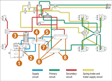
Diagram 12-1: Air Supply Subsystem Circuit Diagram
- Air compressor
- Governor
- Air dryer
- Supply (wet) tank
- Safety valve
- Air tank drain valves
- One-way check valves
- Primary and secondary (dry) tanks
Note: This is only a sample circuit diagram. Components and their positions may be different on your vehicle.
Coach or Bus Brake Subsystem Circuit Diagram
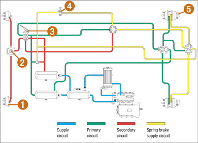
Diagram 12-2: Coach or Bus Brake Subsystem Circuit Diagram
- Service brake chambers
- Front wheel-limiting valve
- Brake pedal
- Spring brake control valve
- Spring brake chambers
Note: This is only a sample circuit diagram. Components and their positions may be different on your vehicle.
Towing-Vehicle Brake Subsystem Circuit Diagram
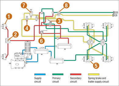
Diagram 12-3: Towing-Vehicle Brake Subsystem Circuit Diagram
- Service brake chambers
- Front wheel-limiting valve
- Brake pedal
- Spring brake control valve
- Spring brake chambers
- Hand valve
- Trailer supply valve
- Tractor protection valve
Note: This is only a sample circuit diagram. Components and their positions may be different on your vehicle.
Trailer Brake Subsystem Circuit Diagram
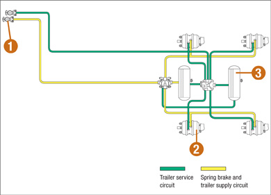
Diagram 12-4: Trailer Brake Subsystem Circuit Diagram
- Trailer couplers "gladhands"
- Spring brake chambers
- Air tanks
Note: This is only a sample circuit diagram. Components and their positions may be different on your vehicle.
Brake Adjustment Limits Chart
Clamp-type Chambers
| Size | Marking | Outside Diameter | Adjustment Limit |
|---|---|---|---|
| 6 | None | 4-1/2" (115mm) | 1-1/4" (32mm) |
| 9 | None | 5-1/4" (133mm) | 1-3/8" (35mm) |
| 12 | None | 5-11/16" (144mm) | 1-3/8" (35mm) |
| 16 | None | 6-3/8" (162mm) | 1-3/4" (45mm) |
| 16 L | L Stamped In Cover, Stroke Tag | 6-3/8" (162mm) | 2" (51mm) |
| 20 | None | 6-25/32" (172mm) | 1-3/4" (45mm) |
| 20 L | L Stamped In Cover, Stroke Tag | 6-25/32" (172mm) | 2" (51mm) |
| 24 | None | 7-7/32" (183mm) | 1-3/4" (45mm) |
| 24 L | L Stamped In Cover, Stroke Tag | 7-7/32" (183mm) | 2" (51mm) |
| 24 LS | Square Ports, Tag & Cover Marking | 7-7/32" (183mm) | 2-1/2" (64mm) |
| 30 | None | 8-3/32" (205mm) | 2" (51mm) |
| 30 | DD3 (Bus/Coach) | 8-1/8" (206mm) | 2-1/4" (57mm) |
| 30 LS | Square Ports, Tag & Cover Marking | 8-3/32" (205mm) | 2-1/2" (64mm) |
| 36 | None | 9" (228mm) | 2-1/4" (57mm) |
Note: L denotes the long-stroke pushrod design.
Note: LS denotes the long-stroke pushrod design with square ports.
Conversion Charts
kPa to psi
| kPa | psi | kPa | psi |
|---|---|---|---|
| 5 | 3/4 | 300 | 43 |
| 10 | 1-1/2 | 350 | 51 |
| 15 | 2-1/4 | 400 | 58 |
| 20 | 3 | 450 | 65 |
| 25 | 3-1/2 | 500 | 72 |
| 30 | 4-1/4 | 550 | 80 |
| 35 | 5 | 600 | 87 |
| 40 | 5-3/4 | 650 | 94 |
| 45 | 6-1/2 | 700 | 101 |
| 50 | 7-1/4 | 750 | 109 |
| 60 | 8-3/4 | 800 | 116 |
| 70 | 10 | 850 | 123 |
| 80 | 11-1/2 | 900 | 130 |
| 90 | 13 | 950 | 138 |
| 100 | 14-1/2 | 1000 | 145 |
| 150 | 22 | 1050 | 152 |
| 200 | 29 | 1100 | 159 |
| 250 | 36 | N/A | N/A |
psi to kPa
| psi | kPa | psi | kPa |
|---|---|---|---|
| 1 | 7 | 60 | 414 |
| 2 | 14 | 65 | 449 |
| 3 | 21 | 70 | 483 |
| 4 | 28 | 75 | 518 |
| 5 | 35 | 80 | 552 |
| 6 | 41 | 85 | 587 |
| 7 | 48 | 90 | 621 |
| 8 | 55 | 95 | 655 |
| 9 | 62 | 100 | 690 |
| 10 | 69 | 105 | 725 |
| 15 | 103 | 110 | 759 |
| 20 | 138 | 115 | 794 |
| 25 | 173 | 120 | 828 |
| 30 | 207 | 125 | 863 |
| 35 | 242 | 130 | 897 |
| 40 | 276 | 135 | 932 |
| 45 | 311 | 140 | 965 |
| 50 | 345 | 145 | 1000 |
| 55 | 380 | 150 | 1035 |
Imperial to Metric Converter
| From | To | Multiply By |
|---|---|---|
| inches | centimetres | 2.54 |
| miles | kilometres | 1.61 |
| feet | metres | 0.31 |
| pounds | kilograms | 0.46 |
| miles per hour | kilometres per hour | 1.61 |
Metric to Imperial Converter
| From | To | Multiply By |
|---|---|---|
| centimetres | inches | 0.39 |
| kilometres | miles | 0.62 |
| metres | feet | 3.28 |
| kilograms | pounds | 2.21 |
| kilometres per hour | miles per hour | 0.61 |