Station and Probe Siting Criteria
5. Station and Probe Siting Criteria
This section describes siting criteria applicable to ambient air monitoring stations, probes, samplers and meteorological sensors. It is largely based on the US Code of Federal Regulations3 (CFR). The section also uses siting criteria information from the ECCC document entitled National Air Pollution Surveillance Network Quality Assurance and Control Guidelines1. Criteria for the siting and exposure of meteorological sensors are based on US EPA4 and World Meteorological Organization (WMO)5 guidance documents.
Siting criteria are included for monitoring the following parameters: SO2, TRS, NOx, CO, O3, particulate matter (SP, PM10, PM2.5 and dustfall), PAH, VOC, fluoridation rate and meteorological parameters (wind speed/direction, temperature and solar radiation).
When planning a new air quality monitoring station, the emitter/proponent should consult with the ministry early in the process. Monitoring plans must be submitted to the ministry and approved prior to the commencement of air quality monitoring activities (Section 1.5).
5.1 Station Siting Criteria
Appendix D of the US EPA Title 40 CFR3 focuses on the relationship between monitoring objectives and the geographical location of monitoring stations. To clarify the nature of this relationship, the concept of spatial scale of representativeness of a monitoring station is defined. The goal in siting stations is to match correctly the spatial scale represented by the sample of monitored air with the spatial scale most appropriate for the monitoring objective of the station. Thus the spatial scale of representativeness is described in terms of physical dimensions of the air parcel nearest to a monitoring station throughout which actual pollutant concentrations are reasonably similar.
The US EPA 40 CFR defines scales of representativeness ranging from microscale to national and global scales. For the purposes of ambient air monitoring of emissions from industrial sources, the scales of representativeness will typically range from the microscale to possibly the urban scale. These are defined in the US EPA 40 CFR as follows:
Microscale - defines concentrations in air volumes associated with area dimensions ranging from several metres up to about 100 metres;
Middle scale - defines concentrations typical of areas up to several city blocks in size with dimensions ranging from about 100 metres to 0.5 kilometres;
Neighbourhood scale - defines concentrations within some extended area of a city that has relatively uniform land use with dimensions in the 0.5 to 4.0 kilometres range; and,
Urban scale - defines the overall, citywide conditions with dimensions on the order of 4.0 to 50 kilometres.
These scales of representativeness relate to the following basic monitoring objectives typically associated with monitoring industrial sources of emissions: compliance with regulatory requirements, population exposure and impact of emissions. Air emission inventories, population density, climatological data, geographical/land use information (GIS), dispersion modelling, public complaints about air quality and the results of short-term screening studies conducted with portable samplers, etc. are all useful in the station site selection process.
5.2 Probe Siting Criteria
Appendix E of the US EPA 40 CFR3 contains specific criteria applicable to locating ambient air monitoring probes after the general station siting has been selected based on the monitoring objectives and spatial scale of representation.
The probe siting criteria discussed below must be followed as closely as possible. It is recognized that practical considerations may require some deviations from the criteria. In such a case, the reasons must be thoroughly documented in a written request for approval by the emitter’s district office of the ministry. Conditions under which the ministry may grant a deviation from the criteria will be similar to those listed in section 11 of Appendix E of the US EPA 40 CFR.
The following is a description of the probe siting criteria by pollutant of interest for ambient air quality monitoring of emissions from industrial point sources. A summary of the criteria, by pollutant, is also presented in Table 3.
5.2.1 Sulphur Dioxide/Total Reduced Sulphur (SO2/TRS)
The probe must be located between 3 and 15 metres above ground and must also be at least 1 metre vertically or horizontally away from any supporting structures, walls, parapets, penthouses, etc. Inlet probes protruding from walls are undesirable and are to be avoided. If the probe is located near the side of a building, then it should be on the side of the building facing the point source being monitored. No furnace, incineration flues or other sources of SO2 and or TRS should be nearby (separation distance should take into account the height of flues, type of waste or fuel burned).
5.2.2 Nitrogen Oxides (NO2)
In siting NO2 analyzers for industrial point source monitoring, it is important to minimize interferences from automotive sources. For neighbourhood and urban scale monitoring, the table below provides required minimum separation distances between a roadway and a probe for various ranges of daily roadway traffic (smaller separation distances than listed in the table, [i.e., less than 10 metres] would classify the monitoring as middle scale).
| Minimum Separation Distance (metres) | Vehicles per Day |
|---|---|
| 10 | < 10,000 |
| 20 | 15,000 |
| 30 | 20,000 |
| 50 | 40,000 |
| 100 | 70,000 |
| 250 | 110,000 |
5.2.3 Particulate Matter
Suspended Particulate (SP)
For all spatial scales, the SP sampler inlet must be between approximately 2 and 15 metres above ground. When determining the sampling location, roadways need to be taken into consideration as SP has large horizontal and vertical concentration gradients immediately adjacent to roadways. The sampler inlet must be at least 1 metre (vertical) and at least 2 metres (horizontal) from a supporting structure (for a rooftop location, the 2 metre separation distance is from walls, parapets or penthouses located on the roof). No furnace or incineration flues should be nearby.
The distance from the sampler to obstacles such as buildings must be at least twice the height of the obstacle protruding above the sampler. The airflow around the sampler must be unrestricted in three of the four cardinal wind directions. There must be no significant obstruction between the sampler and the point source even though other spacing from obstruction criteria are met. Trees provide surfaces for particulate deposition and also restrict airflow, thus the sampler should be placed at least 20 metres from trees.
To minimise the impact of windblown dusts, the SP sampler should not be located in an unpaved area unless there is good vegetative ground cover. For ground level installations, it is highly recommended to install the sampler on a stand (0.5 to 1.0 metre above ground) and to direct the exhaust of the sampler away from the sampler using appropriate ducting. Locations near unpaved parking lots, stockpiles or other fugitive sources are to be avoided unless these sources are part of the monitoring objectives. Activities generating particulate emissions, such as grass cutting near the samplers, are to be avoided on sampling dates.
PM10 and PM2.5 (discrete sampler)
Many of the sample inlet siting criteria are similar to those for SP sampling, and notwithstanding the differences noted below, the criteria for SP sampling must be followed.
While PM10 and PM2.5 exhibit dispersion properties of both gases and settleable particulates, they show vertical and horizontal gradients. PM10 and PM2.5 inlets should be placed at breathing height. However, practical factors such as prevention of vandalism, security and safety precautions must also be considered when siting a particulate sampler.
Given these considerations, the sampler inlet height for microscale PM10 and PM2.5 samplers must be 2 to 7 metres above ground level. For middle or larger spatial scales, increased diffusion results in smaller vertical concentration gradients than for the microscale, and hence the required air intake is 2 to 15 metres above ground.
The sampler inlet should be at least 5 metres from the nearest natural gas combustion exhaust. Sampler inlets should be placed at least 25 metres from major roadways to minimize their influence when monitoring industrial sources.
PM10 and PM2.5 (continuous monitor)
Continuous PM samplers such as the Tapered Element Oscillating Microbalance (TEOM), Beta Gauge or Beta Attenuation Monitor (BAM), etc. require vertical installation of an inlet probe through the roof of the shelter, and according to the instrument operating manual, the sample line must form a straight line with the probe inlet of the sensor unit. Other than this, the probe siting criteria are very similar to those for sampling particulate with discrete samplers: the probe must be located 2 to 15 metres above ground, be at least 1 metre (vertical) 2 metres (horizontal) from support structures and at least 20 metres from trees. The distance from the probe to nearby obstacles such as buildings must be at least twice the height of the obstacle protruding above the probe. Unrestricted airflow is required in three of four cardinal wind directions and the separation distance requirements for discrete particulate samplers from roads and furnace and/or incineration flues apply as well.
Dustfall
The sampling method is described in American Standard for Testing and Materials (ASTM) Method D1739-98 and also in ministry Method DF-E3043A. Dustfall consists of the very coarse particulate matter fraction that settles quickly under the influence of gravity and can result in soiling and nuisance issues. It may contain components of concern for human health (e.g., lead) and can cause damage to nearby vegetation (e.g., salt cake). Although the sampling method is not considered to be rigorous, some regulatory agencies find it useful to determine off-property impacts of coarse particulate emissions from certain industrial source sectors (e.g., cement, aggregate and primary wood products emitters), and have applicable guidelines/criteria. A copy of Method DF-E3043A is available from the ministry’s Laboratory Services Branch (LaSB), Customer Services at
The dustfall sampling method is subject to much interference, such that natural materials (e.g., leaves, insect parts, bird droppings, etc.) not associated with the industrial emissions being monitored can easily bias the results. Hence, both the lab analytical method and the siting criteria must be followed to meet the objectives of the sampling program.
The dustfall collector (polymer jar) should be held in a suitable bracket affixed to a telephone/electrical utility pole (approval from the local utility should be obtained for everyone’s safety) or other supporting device, approximately 3 metres above ground. This vertical separation distance is to minimize re-entrainment of particulate matter from the ground and also to minimize and prevent vandalism. Health and safety concerns regarding the use of ladders to change the jars are best addressed by the use of a long pole equipped with a suitable bracket.
The sampling sites should be selected to avoid unpaved roadways and parking lots, preference being given to sites with good vegetative cover. Also any fugitive source(s) should be documented or preferably avoided through suitable separation distances, depending on the objective of the sampling program. The sampler should be at least 20 metres from buildings, trees and other significant obstacles. There should be unrestricted air flow in three of the four cardinal points, especially between the sampler and the emission source(s) being monitored. For rooftop installations, the sampler should not be near chimneys or flues that could emit soot/coal or other coarse dust and should be positioned away from the edges of the roof to avoid building wake wind effects.
5.2.4 Polycyclic Aromatic Hydrocarbons (PAH)
Since PAH in ambient air are associated mostly with fine particulate matter, the sampler inlet siting criteria is the same as for sampling particulate matter. Hence the sampler inlet height must be 3 to 15 metres above ground and the separation distances from obstacles and furnace/incineration flues etc., is as required for sampling particulate Within the scope of the monitoring objectives, a critical consideration in siting a PAH sampler is to avoid possible nearby PAH sources which could interfere with the sample results. Hence PAH samplers must not be installed on asphalt rooftops and sampling should not be undertaken near sites when rooftop tarring and roadway/parking lot paving activities are occurring.
Cigarette smoke contains PAH. PAH samplers should not be placed near designated smoking areas, and if possible, a “no smoking” sign should be placed near the sampler. Care must be taken when handling PAH samples since a noticeable amount of PAH can be transferred to a filter – everyone should wear gloves when handling filters.
PAH filters typically are shipped in aluminum foil that may potentially be contaminated with paraffin wax. Please ensure with the accredited lab that this is not the case.
5.2.5 Volatile Organic Compounds (VOC)
The sampler inlet siting criteria are the same as for sampling PAH. Within the scope of the monitoring objectives, care must be taken to avoid nearby VOC sources (e.g., automobile exhaust, furnace/incineration flues, etc.) which could interfere with the sample results. Hence minimum separation distances from roadways, specified for monitoring NOx, are required.
5.2.6 Dioxins and Furans (PCDD/PCDF)
The sampler inlet siting criteria are the same as for sampling PAH and particulate matter. Within the scope of the monitoring objectives, care must be taken to avoid possible known nearby sources of PCDD/PCDF which could bias the sample results. Hence minimum separation distances from such sources, using the range of criteria referenced in this document and knowledge of local conditions are required.
5.2.7 Fluoride Sampling
Passive and active sampling methods can be employed to determine the particulate and gaseous fluorides in ambient air.
Passive Sampling – Fluoridation Rate
Sampler siting criteria for the use of lime candles follow the guidelines for siting particulate samplers and trace gas monitors. The candle is usually protected from the elements using a louvered shelter positioned 2 to 3 metres above ground. The sampling site should be located more than 20 metres from trees and its distance from any air flow obstacle must be greater than twice the height of the obstacle above the sampler. Airflow must be unrestricted through an arc of at least 270 degrees.
Active Sampling
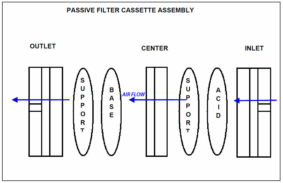
The active sampling method for fluorides follows the dual filter pack method (MOE, 1982). Active samples are collected over a 24 hour period with a start time of 12:00 a.m. (00:00). This method involves drawing a known air volume at a fixed rate through an acid-treated filter paper to collect particulate, which may contain fluoride, and then through an alkali-treated filter to collect fluoride gases. The remaining volume of air is exhausted out of the outlet end of the dry gas metres recording the volume. The two filters are held one above the other in a specially constructed filter holder referred to as a dual filter pack, or assembly, which provides a separate space for each filter. Please refer to the diagram below.
The dual filter assemblies should be positioned 2 to 3 meters above ground. The sampler should be located more than 20 metres from trees, and its distance from any air flow obstacle must be greater than twice the height of the obstacle above the sampler. Airflow must be unrestricted through an arc of at least 270 degrees.
There may be several dual filter assemblies connected to an appropriate manifold equipped with electrically controlled valves programmed to allow sequential operation. The filters are then removed from the sample, treated to dissolve soluble fluorides and analysed by the specific ion electrode method. After removal of the soluble fluorides, the filters may be processed to determine the insoluble content according to a separate procedure (ASTM D3266-79, ASTM D3269-79, EPA Method 300).
Within the scope of the monitoring objectives, care must be taken to try to avoid possible nearby sources of fluorides which could interfere with the sample results. Hence, minimum separation distances from such sources, using the range of criteria referenced in this document and knowledge of local conditions, are required.
5.2.8 Asbestos
The sampler inlet siting criteria are the same as for sampling PAH. Within the scope of the monitoring objectives, care must be taken to avoid nearby asbestos sources which could interfere with the sample results.
5.2.9 Passive Samplers
Passive diffusion sampling provides a cost-effective indicator of the ambient conditions in an area where there may be no power, qualitative results are adequate, or to assist in identifying representative monitoring locations. For credible results, it is recommended that at least duplicate passive samplers be used at each monitoring location. Care must be taken not to touch the diffusion barriers when handling the cartridges or to let the samplers fall to the ground.
Passive samplers sample gaseous pollutants, such as SO2, NO2, O3, hydrogen sulphide (H2S), ammonia (NH3) and NOx, at a sampling rate controlled by diffusion through a static air layer or by permeation through a membrane. Passive samplers are generally simple in structure and do not require electricity. The passive sampling system needs to be installed in a specially designed rain shelter 1 to 3 metres above the ground. The rain shelters also help prevent interference from animals, human beings or the surroundings. After exposure, the samplers are analysed by a laboratory.
A passive sampler’s sampling rate depends on many factors such as temperature, relative humidity, wind direction, wind speed, sampler’s structure and collection media. If a passive sampler will be used year round, the sampling rate needs to be determined. During sampling, the exposure time, as well as the average temperature, relative humidity and wind speed need to be recorded.
| Pollutant | Height Above Ground (metres) |
Distance from Supporting Structure (metres) Vertical |
Distance from Supporting Structure (metres) Horizontal1 |
Other Spacing Criteria |
|---|---|---|---|---|
| SO2 and TRS | 3 to 15 | >1 | >1 |
|
| NOx (middle scale) | 3 to 15 | >1 | >1 |
|
| NOx (neighbourhood scale) | 3 to 15 | >1 | >1 |
|
| CO | 3 to 10 | >1 | >1 |
|
| SP / PM10 (both spatial scales) |
2 to 15 | >1 | >2 |
|
| PM10 and PM2.5 (discrete sampler) |
2 to 73 2 to 154 |
>1 >1 |
>2 >2 |
|
| PM10 and PM2.5 (continuous sampler) |
2 to 15 | >1 | >2 |
|
| PAH/Dioxins VOCs | 3 to 15 | >1 | >2 |
|
| Dustfall Fluorides |
3 |
|
1 When a probe is located on a rooftop, this separation distance is in reference to walls, parapets, or penthouses located on the roof
2 Distance depends on the height of furnace or incinerator flues, type of waste or fuel burned, and quality of fuel (sulphur and ash content). This is to avoid undue influence from nearby sources
3 For microscale measurements
4 For middle or larger scale measurements
5 Separation distances from these sources depend on monitoring objectives
5.2.10 Probe Material
In addition to the siting criteria for stations and sample inlet probes, an important requirement is the use of acceptable probe materials. For reactive gases such as SO2 and NO2, only Pyrex glass and Fluorinated ethylene propylene (FEP) Teflon have been found to be acceptable for use as intake sampling lines. For VOC sampling, FEP Teflon is unacceptable because of VOC adsorption and desorption reactions on the Teflon. Acceptable probe materials for VOC sampling are borosilicate glass, stainless steel or its equivalent.
5.2.11 Meteorological Measurements
The meteorological sensor siting and exposure criteria described below are largely based on US EPA and WMO guidance documents4,5 as referenced. Meteorological measurements include measurements of wind speed, wind direction, temperature, barometric pressure, relative humidity and solar radiation. This document will not cover barometric pressure and relative humidity. As a general rule, meteorological sensors should be sited at a distance, which is beyond the influence of obstructions such as buildings and trees. The other general rule is that the measurements should be representative of meteorological conditions in the area of interest. A summary of the criteria for siting meteorological probes is provided in Table 4.
Wind Speed and Direction
To meet the best exposure criteria, sensors to measure wind are usually mounted on towers or masts. If sensors are mounted improperly, errors due to the influence of nearby obstacles and possibly of the tower itself will be introduced into the measurements. Note that wind direction is to be reported as direction from which the wind is blowing.
Except when measurements of extremely local phenomenon are required (from microscale to neighbourhood scale), measurements representative of a fairly large area (urban to regional scale) are desired. Care must be taken to ensure that the measurements are not adversely influenced by nearby obstacles. The WMO has recommended that the standard height at which surface wind measurements should be taken is 10 metres (however measurements at a height of 3 metres are acceptable for tripod-mounted sensors). Depending on the monitoring objectives/requirements, there may be circumstances for which wind measurements would best be taken at elevations much higher than 10 metres (minimize topographical effects, tracking of emissions from tall stacks, etc.). Such cases would need the approval of the ministry. Ideally, the measurements should be taken over level, open terrain but if obstructions, such as buildings, are present in the area where wind measurements are to be taken, the following criteria must be observed:
- The sensor must be located a distance upwind of a building equal to at least the building height.
- If the sensor is to be located on the roof of the building, it must be at least one and a half (1.5) building heights above the roof. Wind sensors should only be located on building rooftops as a last resort.
- The sensor must be located a distance of at least 5 to 10 building heights downwind of the building.
For rough terrain or valley situations, local effects such as channelling, slope and valley winds need to be considered in the design of the monitoring program. If the program focuses on elevated sources of emissions, it may be desirable to avoid local wind influences. If the emissions of interest are from ground level sources, local influences require careful consideration and the siting of the wind sensors must take into account nearby topographical features, which could unduly influence the measurements.
In addition to the general rules concerning obstructions, other considerations are important with respect to sites near trees. Seasonal effects need to be considered for sites near deciduous trees. For dense continuous forests where an open exposure cannot be obtained, measurements should be taken 10 metres above the height of the general vegetative canopy. Any deviation from these guidance requirements should be completed in consultation with, and with approval by, the Regional Office Techhnical Support Section for approval.
If the anemometer and vane are to be installed on the side of a tower, then precautions must be taken to ensure that the wind measurements are not influenced by the tower. Studies have shown that turbulence in the wake of lattice towers is severe and in the wake of solid towers turbulence is extreme, often with flow reversal. Open lattice towers are preferred. To mitigate these effects, the following exposure criteria should be observed:
- The boom should extend outward from a corner of the tower into the wind direction of primary concern.
- The boom should support the sensor at a distance equal to twice the maximum diameter (or diagonal) of the tower away from the nearest point on the tower.
- The wind sensors should be located at heights of minimum tower density, above or below the horizontal cross members.
- If the width of the tower side is D, for a boom length of 1 tower width, i.e., 1D, measurements of wind speed are true to within 10% for a 330° sector of arc.
- For a boom length of 2D, wind speed is accurate to within 10% for a 330° sector of arc. It is recommended that the wind sensor be mounted on booms at a distance of at least 2D from the tower
For these two arcs, wind direction has been found to be accurate to within 5%. On large TV towers, the sector of arc yielding accurate wind measurements may drop to 180° for boom lengths less than 1D. If more accurate wind measurements are required for an arc greater than that produced by the above exposure criteria, it is recommended that two sets of speed and direction sensors be placed 180° apart in the manner prescribed above. A wind sensor mounted on top of a tower should be mounted at least 1D above the top of the tower structure.
Air Temperature
The sensor must be housed in a ventilated radiation shield (aspiration velocity should exceed 3 m/s) to protect the sensor from thermal radiation. The US EPA recommends the sensor be no closer than four times the obstruction’s height and at least 30 metres from large paved areas. Other situations to avoid include: large industrial heat sources, rooftops, steep slopes, tall vegetation, shaded areas, swamps, etc. The WMO standard for ambient air temperature measurements is 2 metres above ground. The US EPA recommends that the sensor be located at least 2 metres above ground, up to a maximum of 10 metres. Vandalism and security need to be considered in the placement of these sensors. Temperature sensors on towers should be mounted on booms at a distance of about 1D (D is the width of the tower side).
Probe placement for temperature difference measurements depend on the application. For use in estimating stable plume rise, temperature difference measurements should be made across the plume rise layer and a minimum separation of 50 metres is recommended.
Solar radiation
Pyranometers used for measuring incoming solar radiation should be located with an unrestricted view of the sky in all directions during all seasons, with the lowest solar elevation angle possible. They should be located to avoid obstructions casting a shadow on the sensor at any time. Sensor height is not critical for these units. A tall platform or rooftop is a desirable location.
Net radiometers should be mounted about 1 metre above ground and in such a fashion as to avoid obstructions to the field of view both upward and downward. The ground cover should be representative of the general site area. The monitoring objective will govern the collection of solar or net radiation data.
| Sensor Type | Height Above Ground (metres) | Exposure Considerations |
|---|---|---|
| Wind speed and direction | 101 |
|
| Air temperature | 21 |
|
| Solar radiation | 13 |
|
1 World Meteorological Organization recommendation; height can be greater depending on monitoring requirements (e.g., tall stacks)
2 Rooftop installations not recommended
3 Height above ground for net radiometers