Environmental design criteria
Environmental design criteria (3.0)
3.1 General
Chapter 2 described watershed and subwatershed plans, as well as the more detailed plans which are now often being completed at the Secondary Plan level. The objectives of the stormwater management design criteria typically provided in such plans are to:
- Preserve groundwater and baseflow characteristics;
- Prevent undesirable and costly geomorphic change in the watercourse;
- Prevent any increase in flood risk potential;
- Protect water quality; and ultimately
- Maintain an appropriate diversity of aquatic life and opportunities for human uses.
These criteria are developed considering the interactions and cumulative effects which may be expected from urban growth. Cumulative impacts refer to the combined effect of numerous single developments.
Urban development without watershed/subwatershed planning is discouraged because of the difficulty in addressing many environmental impacts at a plan of subdivision or site plan level. Where guidance from a watershed/subwatershed plan is not available, approvals may be delayed due to incomplete information requirements which may extend off site and include:
- cumulative impact of urbanization on aquatic resources;
- wildlife corridors;
- natural area linkages;
- surface and subsurface flow paths;
- rehabilitation areas;
- cumulative impact of individual subdivision/site water management practices; and
- visual impacts.
Although development planning using the subwatershed approach is preferred, there will be cases where a development will be allowed to proceed without a subwatershed plan. While there may be many factors which necessitate this, in general it will occur when the scale of the proposed development is small, the overall level of watershed development (i.e., imperviousness) is limited, and the receiving stream is not overly sensitive in terms of aquatic resources, geomorphology or flooding, nor severely degraded in terms of water quality. The proposed development will typically be an infill (surrounded by existing development), a replacement for existing development, an isolated urban development serving a particular need, or an expansion of the urban fringe. In most cases where a development is allowed to proceed without subwatershed planning, the preparation of a subwatershed plan is determined to be cost ineffective (e.g., there is very little foreseen future development) or cost prohibitive in the near future. The decision to proceed without a subwatershed plan must be confirmed with the approval agencies.
In the absence of watershed/subwatershed planning, subdivision/site planning must occur to ensure that the development is planned with due regard to the surrounding environment. Resource mapping, as described in Appendix A, must be prepared since there will not be any commensurate mapping from a subwatershed plan. This chapter provides guidance on establishing stormwater management design criteria to mitigate the effects of urbanization on the water balance, water quality, stream morphology, and water quantity. Although most of the discussion is focussed on end-of-pipe facilities, lot level and conveyance controls should be utilized to the extent possible in order to maintain the pre-development hydrologic regime and reduce the size of the end-of-pipe facilities.
In some cases, stormwater may be discharged to a receiving drainage system that is part of a highway drainage system such as a highway roadside ditch or a highway storm sewer system. In such cases the impacts on these drainage systems may determine the level of stormwater management control required. Constraints can also be placed by the design capacity and impact of an existing highway culvert or bridge located downstream of a development site. Land development proposals may require approvals from the Ministry of Transportation (MTO) before proceeding. Guidance on how to satisfy MTO requirements and on the design considerations and design practices of stormwater management facilities adjacent to highways can be found in the following references:
- MTO Drainage Management Manual, 1997.
- MTO Stormwater Management Requirements for Land Development Proposals, 1999.
3.2 Water balance
3.2.1 Modelling
As described in Section 1.3, urbanization may reduce groundwater recharge which in turn may reduce baseflow, leading to the impairment of aquatic habitats, as well as the water available for domestic, agricultural, or other uses. Therefore, it is necessary to predict the effect of urban development on the subsurface portion of the hydrologic cycle.
Ideally, this may be accomplished using a groundwater modelling approach. An analysis may be conducted to evaluate the sensitivity of the system to reduced recharge and how urbanization may ultimately affect water users or aquatic habitats. The benefit of this approach is that the sensitivity of the groundwater system, not only to the quantity of recharge but also, to the spatial distribution of recharge may be examined. Once developed, a groundwater model may also be used to evaluate alternative mitigation techniques.
The utility of a modelling approach however, is highly dependent upon the quantity of data required to characterize the subsurface system (i.e., complexity of hydrogeologic system) and the quantity and quality of data which is available or may be collected. It may not be feasible to satisfy the relatively intensive data requirements for modelling. Modelling used without discretion may lead to poor decisions. It is important to stress that care must be taken not to accept results which cannot be defended because of poor quality input to a model.
3.2.2 Water balance methods
In cases in which the available data cannot support more sophisticated approaches, water balance methods are more appropriate for predicting the changes to the hydrologic cycle that may result from urban development. They can be used to determine amounts of water that should be infiltrated to compensate for reductions caused by large paved areas or changes to vegetation.
The water balance method developed by Thornthwaite and Mather (1957) determines the potential and actual amounts of evapotranspiration and water surplus (or excess of precipitation over evapotranspiration). Infiltration factors are used to determine the fraction of water surplus that infiltrates into the ground and the fraction that runs off to nearby streams. Thornthwaite and Mather’s method requires monthly or daily precipitation, monthly or daily temperature, latitude of the site, vegetation type, soil type, and a series of tables. The tables define a heat index, potential evapotranspiration, water holding capacity, and soil moisture retention. Snowfall, and alternating wet and dry cycles are included. Soil water holding capacity is dependent upon the soil type, soil structure and the type of vegetation growing on it. The Thornthwaite and Mather water balance method assumes mature vegetation and does not account for growing seasons where evapotranspiration would be less for immature vegetation.
3.2.3 Water balance example
Water balances should be calculated on a site by site basis. Table 3.1 shows the results of a water balance for various vegetation covers in different soil types for a basin in southern Ontario with a latitude of 45°. Infiltration factors were calculated for each soil and vegetation type and were determined for rolling land. More details on infiltration factors can be found in "Hydrogeological Technical Information Requirements for Land Development Applications" (MOE, 1995).
The results shown in Table 3.1 were computed using average annual monthly values. More accurate answers would be obtained using monthly recorded precipitation and temperature for a period of 10 to 20 years. Depending upon the quality of other inputs to the method, the accuracy of the water balance results may be further improved if daily precipitation and temperature values are used.
Tables 3.1: hydrologic cycle component values
| Soil group | Water Holding Capacity(mm) | Hydrologic Soil Group | Precipitation (mm) | Evapo-transpiration (mm) | Runoff (mm) | Infiltration*(mm) |
|---|---|---|---|---|---|---|
| Fine Sand | 50 | A | 940 | 515 | 149 | 276 |
| Fine Sandy Loam | 75 | B | 940 | 525 | 187 | 228 |
| Silt Loam | 125 | C | 940 | 536 | 222 | 182 |
| Clay Loam | 100 | CD | 940 | 531 | 245 | 164 |
| Clay | 75 | D | 940 | 525 | 270 | 145 |
| Soil group | Water Holding Capacity(mm) | Hydrologic Soil Group | Precipitation (mm) | Evapo-transpiration (mm) | Runoff (mm) | Infiltration*(mm) |
|---|---|---|---|---|---|---|
| Fine Sand | 75 | A | 940 | 525 | 125 | 291 |
| Fine Sandy Loam | 150 | B | 940 | 539 | 160 | 241 |
| Silt Loam | 200 | C | 940 | 543 | 199 | 199 |
| Clay Loam | 200 | CD | 940 | 543 | 218 | 179 |
| Clay | 150 | D | 940 | 539 | 241 | 160 |
| Soil group | Water Holding Capacity(mm) | Hydrologic Soil Group | Precipitation (mm) | Evapo-transpiration (mm) | Runoff (mm) | Infiltration*(mm) |
|---|---|---|---|---|---|---|
| Fine Sand | 100 | A | 940 | 531 | 102 | 307 |
| Fine Sandy Loam | 150 | B | 940 | 539 | 140 | 261 |
| Silt Loam | 250 | C | 940 | 546 | 177 | 217 |
| Clay Loam | 250 | CD | 940 | 546 | 197 | 197 |
| Clay | 200 | D | 940 | 543 | 218 | 179 |
| Soil group | Water Holding Capacity(mm) | Hydrologic Soil Group | Precipitation (mm) | Evapo-transpiration (mm) | Runoff (mm) | Infiltration*(mm) |
|---|---|---|---|---|---|---|
| Fine Sand | 250 | A | 940 | 546 | 79 | 315 |
| Fine Sandy Loam | 300 | B | 940 | 548 | 118 | 274 |
| Silt Loam | 400 | C | 940 | 550 | 156 | 234 |
| Clay Loam | 400 | CD | 940 | 550 | 176 | 215 |
| Clay | 350 | D | 940 | 549 | 196 | 196 |
Notes: Hydrologic Soil Group A represents soils with low runoff potential and Soil Group D represents soils with high runoff potential. The evapotranspiration values are for mature vegetation. Streamflow is composed of baseflow and runoff.
* This is the total infiltration of which some discharges back to the stream as base flow. The infiltration factor is determined by summing a factor for topography, soils and cover.
| Flat Land, average slope < 0.6 m/km | 0.3 |
| Rolling Land, average slope 2.8 m to 3.8 m/km | 0.2 |
| Hilly Land, average slope 28 m to 47 m/km | 0.1 |
| Tight impervious clay | 0.1 |
| Medium combinations of clay and loam | 0.2 |
| Open Sandy loam | 0.4 |
| Cultivated Land | 0.1 |
| Woodland | 0.2 |
As shown in the following simple example, Table 3.1 can be used to determine infiltration amounts for varying land uses:
Pre-development conditions
The site area is approximately 10.0 ha with pasture type vegetation in fine sand soil. The average annual site infiltration would be approximately 307 mm or approximately 30,700 m³ (307 mm × 10.0 ha).
Post-development conditions
Of the total site area 3.5 ha (35 %) would be converted to impervious area. The infiltration for this area would be 0 mm. The remaining 6.5 ha of the site (65 %) is assumed to be covered with urban lawns (shallow rooted crops) with an average annual infiltration of 276 mm or approximately 17,940 m³ (276 mm × 6.5 ha). There would be a net reduction in infiltration of 12,760 m³. If the reduction has a significant impact, then 12,760 m³, or some portion of it, may have to be infiltrated using SWMPs.
3.3 Water quality
3.3.1 Criteria development
During the development of the 1994 SWMP Manual, a review of the existing water quality criteria in Canada and the United States was made. The primary criteria used in most jurisdictions were volumetric (i.e., runoff from a specified design storm was to be captured and treated). In most cases the selected design storm ranged from 12.5 mm to 25 mm. The use of this type of volumetric design storm criteria remains prevalent today, although some jurisdictions have established methods for refining the size of the design event, based on area-specific conditions such as climate or the receiving water body.
An alternate approach to the volumetric sizing of stormwater facilities has been applied in Ontario. Computer modelling of end-of-pipe stormwater management facilities was undertaken to assess the variation in pollutant removal with SWMP type and level of imperviousness. The modelling results were based on many assumptions, primarily related to the proper design of facilities, and the theoretical build-up, wash-off and settling of sediment particles. The approach however allowed the development of volumetric criteria that reflected a twenty year period of climatic record. This meant that the effect of storms in series (i.e., several storms in a few days), event overflows and winter melt conditions were accounted for in selecting the volumetric criteria. It also allowed specification of the volumetric criteria according to some basic characteristics of the different SWMP types (e.g., depth, detention time). An assessment of regional variations in climate indicated that the same volumetric guidelines could be used throughout the province.
The continuous simulation models yielded several useful, theoretical findings:
- The amount of suspended solids settling for a given design storage varies with SWMP type because of their inherent design characteristics. SWMPs therefore require different volumes of storage to provide the same suspended solids removal performance.
- The volume of water in the permanent pool of a wet facility (wet pond, wetland) is more important than the active storage component (that portion of a facility that drains after an event) for suspended solids removal.
- The suspended solids removal performance becomes asymptotic with increasing design storage (there is a limit to storage beyond which there are negligible increases in suspended solids settling).
The variation in performance with SWMP type was explained by the typical configurations of the facilities and the different removal mechanisms. For example, infiltration type SWMPs were assumed to remove 90% to 95% of the suspended solids from water which was infiltrated. This results in a high removal efficiency if the storage is large enough to contain the storm (or polluted portion of the storm). The model only looked at sedimentation, and assumed that re-suspension of previous settled pollutants would not occur. Therefore, wetlands were more effective than wet ponds since they were modelled with a shallower depth.
The importance of the permanent pool was seen to be considerable. The simulations that were conducted indicated that a wet pond without any extended detention storage was still highly effective for solids settling. The results can be explained by the hydraulic operation of these facilities. During a storm, the influent loading is diluted in the permanent pool. Any discharge from the pond during the storm event is therefore diluted (given that the configuration of the pond is appropriately designed). After the storm has subsided there is still a considerable volume of suspended solids which is trapped in the permanent pool and has not settled. These solids have the inter-event times (i.e., 2 to 3 days on average) to settle out in the pond. This combined action of dilution and inter-event settling makes wet facilities efficient.
The diminishing return for large storage volumes can be explained by the frequency distribution of rainfall events. Once the storage exceeds the volume of most small runoff events, the excess storage provides limited benefit. This is particularly true in terms of the permanent pool volume.
The results of modelling led to the development of volumetric criteria which differed in several major aspects from those found in other jurisdictions:
- For wet facilities, the importance of the permanent pool was recognized by specifying a maximum active storage volume (relative to the total volume);
- Different volumetric criteria were specified for the major classes of SWMP to reflect their varying removal efficiencies (which result from their inherent design); and
- Different volumetric criteria were recommended according to the predicted level of long-term sediment removal.
3.3.1.1 Level of protection
The federal Fisheries Act prohibits "the deposit of a deleterious substance of any type in water frequented by fish or in any place under any conditions where the deleterious substance or any other deleterious substance that results from the deposit of the deleterious substance may enter any such water" (subsection 36(3)). Any substance with a potentially harmful chemical, physical (including temperature) or biological effect on fish or fish habitat is considered to be deleterious. The "first-order" impacts of stormwater runoff are primarily related to suspended solids (SS), however, so the design of facilities is usually based on the long-term removal of SS from the stormwater discharge.
The federal Fisheries Act does not differentiate between different types of habitat, but Fisheries and Oceans Canada (Fish Habitat Management) does recognize that some habitats are more resilient to perturbation. Based on this, the levels of protection should be chosen to maintain or enhance the existing aquatic habitat. The level of water quality protection given in watershed management plans, fisheries management plans, official plans, official plan amendments, plans of subdivision, site plans, or other environmental management plans should be adhered to when designing stormwater management facilities. In the absence of these plans, it is possible to select the desired level of protection based on the characteristics of the receiving watercourse. However, the decision regarding the level of protection needed should be made based on input from a qualified aquatic biologist. While general guidance is provided below on the level of protection recommended for the different habitat types, the level of protection should be based on site-specific conditions determined through quantification of pre-development suspended solids loadings to receiving waters and the sediment loading characteristics of the receiving waters. This will require examination of the existing receiving water aquatic habitat and its interaction with the surrounding terrestrial habitat through instream sampling, soil type delineation, vegetation cover, and existing aquatic species inventory as required to justify the level of protection.
Three levels of protection are given, with the goal to maintain or enhance existing aquatic habitat, based on the suspended solids removal performance for the different end-of-pipe stormwater management facilities developed in the continuous simulation modelling. Descriptions of the habitat characteristics corresponding to the three levels of protection are given below.
Enhanced protection
Enhanced protection or greater should be used when sensitive aquatic habitat will be impacted by end-of-pipe discharge. Generally this will include receiving waters that have aquatic communities that have adapted to a low suspended solids environment. Conditions where a minimum of enhanced protection should be used include:
- Areas with high permeability soils (i.e., Soil Conservation Service (SCS) hydrologic classes A and B) conducive to infiltration resulting in low suspended solids loadings from the pre development site;
- Habitat sensitive to sediment and siltation (such as gravel bottom used for bass or brook trout spawning);
- High baseflow discharge areas (such as groundwater upwellings important to brook trout);
- Low upstream sediment loads resulting in clear surface water important to maintaining habitat for sight feeding fish species (such as bass, northern pike, lake trout, and brook trout); and
- Low pre development erosion characteristics (such as dense vegetation, or erosion resistant soils).
Normal protection
Normal protection can be considered when conditions for enhanced protection do not exist. Example habitats where normal protection may be appropriate include:
- Areas with moderate, natural upstream sediment loads (such as some walleye feeding habitat); and
- Spawning habitat less sensitive to suspended solids loadings (such as aquatic and emergent plant beds used by pike and perch).
If there is no subwatershed plan or fisheries information available on the receiving waters, agencies with fisheries and habitat management responsibilities may require sufficient background study to justify the use of normal protection where there is known potential for sensitive aquatic habitat within a reasonable distance downstream. Responsible agencies should be contacted early in the design process in order to establish a reasonable downstream distance based on specific studies and local conditions. Generally, normal protection will be considered suitable where a stable downstream habitat has adapted to moderate sediment loading.
Basic protection
Basic protection would only be acceptable where the receiving aquatic habitat is demonstrated to be insensitive to stormwater impacts and has little potential for immediate or long-term rehabilitation. Generally, basic protection may be applied in the following conditions:
- Areas where downstream aquatic habitat has adapted to high suspended solid loadings prior to anthropomorphic changes to the watershed (for example, aquatic habitat conditions that may be found naturally in areas of fine grained soils); and
- Downstream watercourses have been significantly altered (by urbanization or agricultural practices), hardened, or polluted, and there is little short or long-term potential for rehabilitation.
Proponents proposing basic treatment must seek approval from the appropriate agencies with fisheries and habitat management responsibilities with clear rational and site-specific supporting data collected from baseline studies or from existing resource management agency data bases (such as, fishery management plans, watershed management plans, etc.).
Agencies with fisheries responsibilities may also require habitat compensation where stormwater management design impacts are determined to result in harmful alteration, disruption, or destruction of fish habitat as defined in the Fisheries Act. Habitat compensation typically involves the replacing of damaged habitat with newly created habitat or improving the productive capacity of other aquatic habitat at or near the area of impact.
The levels of protection are based on a general relationship between the long-term average suspended solids removal of the end-of-pipe stormwater management facilities and the lethal and chronic effects of suspended solids on aquatic life. The levels of protection correspond to the following 'long-term average suspended solids removals' which refer to the removal by the SWM facility of suspended solids from the site runoff for the entire range of rainfall events on that site for a long period of time, at least 10 years. The use of a long-term average is to account for the variability in characteristics of rainfall events.
- Enhanced protection corresponds to the end-of-pipe storage volumes required for the long-term average removal of 80% of suspended solids.
- Normal protection corresponds to the end-of-pipe storage volumes required for the long-term average removal of 70% of suspended solids.
- Basic protection corresponds to the end-of-pipe storage volumes required for the long-term average removal of 60% of suspended solids.
For SWMPs designed with a by-pass, the calculation of long-term suspended solids removal must be based on both suspended solids removal in the facility plus suspended solids by-passed around the facility.
3.3.2 Water quality sizing criteria
The volumetric water quality criteria are presented in Table 3.2. The values are based on a 24 hour drawdown time and a design which conforms to the guidance provided in this manual. Requirements differ with SWMP type to reflect differences in removal efficiencies. Of the specified storage volume for wet facilities, 40 m³/ha is extended detention, while the remainder represents the permanent pool.
| Protection Level | SWMP Type | Storage Volume (m³/ha) for Impervious Level: 35% | Storage Volume (m³/ha) for Impervious Level: 55% | Storage Volume (m³/ha) for Impervious Level: 70% | Storage Volume (m³/ha) for Impervious Level: 85% |
|---|---|---|---|---|---|
| Enhanced 80% long-term S.S. removal | Infiltration | 25 | 30 | 35 | 40 |
| Enhanced 80% long-term S.S. removal | Wetlands | 80 | 105 | 120 | 140 |
| Enhanced 80% long-term S.S. removal | Hybrid Wet Pond/Wetland | 110 | 150 | 175 | 195 |
| Enhanced 80% long-term S.S. removal | Wet Pond | 140 | 190 | 225 | 250 |
| Normal 70% long-term S.S. removal | Infiltration | 20 | 20 | 25 | 30 |
| Normal 70% long-term S.S. removal | Wetlands | 60 | 70 | 80 | 90 |
| Normal 70% long-term S.S. removal | Hybrid Wet Pond/Wetland | 75 | 90 | 105 | 120 |
| Normal 70% long-term S.S. removal | Wet Pond | 90 | 110 | 130 | 150 |
| Basic 60% long-term S.S. removal | Infiltration | 20 | 20 | 20 | 20 |
| Basic 60% long-term S.S. removal | Wetlands | 60 | 60 | 60 | 60 |
| Basic 60% long-term S.S. removal | Hybrid Wet Pond/Wetland | 60 | 70 | 75 | 80 |
| Basic 60% long-term S.S. removal | Wet Pond | 60 | 70 | 85 | 95 |
| Basic 60% long-term S.S. removal | Dry Pond (Continuous Flow) | 90 | 150 | 200 | 240 |
For levels of imperviousness below 35%, required storage volumes may be obtained by extrapolating the values provided in Table 3.2. For levels of imperviousness between those included in Table 3.2, required storage volumes may be obtained by interpolation.
It should be noted that the total drainage area contributing to the facility should be included in sizing (lumped imperviousness or separate calculations for internal and external drainage areas is permissible) in most cases. The exception occurs when an external drainage area is itself controlled by a separate water quality facility (and erosion and quantity control are either not required or provided separately). Modelling studies (Marshall Macklin Monaghan Limited, 1997) indicate comparable combined long-term removal rates for ponds in series and separate parallel ponds. More frequent overflows will occur from the most downstream pond, but this can be compensated for by doubling the water quality active storage volume from 40 to 80 m³/ha.
The volumetric criteria specified in Table 3.2 address only water quality, not erosion, baseflow or flooding concerns. Furthermore, the criteria were developed based on the removal of suspended solids via settling, and therefore, may not adequately address contaminants which must be removed by other mechanisms.
3.3.3 Results of monitoring SWMP Performance
In the late 1990's a partnership of government agencies pooled their resources to undertake a series of monitoring studies aimed at assessing the water quality performance of selected SWMPs through the Stormwater Assessment and Monitoring Performance (SWAMP) Program (Meek and Liang, 1998). Most of the facilities monitored did not meet the design guidance provided in this or the previous version of the Manual as they were constructed before this guidance was available. Nevertheless, the results of the monitoring program are of use in assessing the performance of stormwater management facilities.
In addition to the efforts conducted under SWAMP, numerous studies of performance have been conducted both inside and outside of Ontario. Most performance studies in Ontario have been of wet pond or pond/wetland systems. Key results of performance studies, and their implications to SWMP design in Ontario, are summarized below.
- The results of performance studies indicate a fair consistency for most end-of-pipe SWMP types (typically 60-80% suspended solids (SS) removal and 40-50% total phosphorus (TP) removal);
- Extremes in performance are observed in all end-of-pipe SWMP types (from negative performance to 99% removal of SS and TP);
- For wet facilities, the volume of the permanent pool appears to be important. Some facilities with no active storage (i.e., those with permanent pool only) have performed well;
- Greater than anticipated removal rates have been observed in some instances. Flocculent settling may be the mechanism for enhanced removal;
- Dry ponds (i.e., those with no permanent pool) may be more effective than previously credited, when longer detention times can be achieved (e.g., 48 hours); and
- Performance can be enhanced through techniques other than adding volume (e.g., extending the flow path with baffles).
Overall, the results point to an optimistic view of SWMP performance, particularly in retro-fit situations. The results, however, continue to show significant variability from facility to facility. There is not currently a sufficient body of monitoring results to warrant alterations to the volumetric criteria specified in Table 3.2. It is also apparent that many factors other than volume can influence the performance of a SWM facility.
The analysis of the results of performance studies suggests that:
- The current volumetric criteria should be retained;
- There should be greater emphasis on meeting other recommended design criteria (use of forebays, minimum length-to-width ratio, etc.);
- The monitoring of facilities should be continued, but that the emphasis should be shifted to assessing the processes and mechanisms (and associated design elements) that govern performance which may require alternate monitoring techniques (such as dye tracing); and
- The use of more sophisticated settling and flow dynamics models should be investigated, for testing SWMP design characteristics.
3.3.4 Other considerations
3.3.4.1 Bacteria
Recreational activities which involve water contact (i.e., swimming) may require additional water quality controls depending on the distance between the development and the recreation area, and the contributing drainage area upstream of the recreation location compared to the size of development. In areas where there are no recreational activities involving water contact, wet stormwater management facilities and infiltration techniques adequately control bacterial loadings (faecal coliform, E. coli).
In instances where the proposed development is greater than or equal to 10% of the drainage area discharging to a swimming or other recreational area of concern, a subwatershed plan should be undertaken to address the cumulative impact of development.
3.3.4.2 Temperature
Temperature is a major concern in regard to fish and their habitat, especially where discharge is to a cold water stream. Urbanization causes temperature increases in stormwater and ponds can compound this increase since open water will tend to acclimate with the ambient air temperature. Design for temperature mitigation is discussed in Section 4.4. Where temperature is a significant concern it is recommended that the designer consult with the local conservation authority, the federal Department of Fisheries and Oceans (Fisheries and Habitat Management) and the Ontario Ministry of Natural Resources, during the design process.
3.4 Erosion control/geomorphology
This sub-section provides an overview of approaches for the design of end-of-pipe (or centralized) Stormwater Management facilities for the control of in-stream erosion potential. The global intent of SWM measures for the control of in-stream erosion potential is the preservation or enhancement of a "stable," sustainable fluvial system and its associated habitat, aesthetic value and education-recreational potential while accommodating development needs. Two design approaches are described:
- a Detailed Design Approach; and
- a Simplified Design Approach.
These approaches incorporate advances in the field of urban geomorphology and stormwater management. In reading the following sections, the following should be kept in mind:
- The processes that control natural channel systems are complex and span a number of disciplines (e.g., geomorphology, biology, engineering). In order to provide an effective approach to designing a stream system that provides or emulates natural stream qualities, the necessary expertise must be available and integrated in the design process;
- The procedure presented for the Detailed Approach is similar to a Nine-Step Protocol developed by the Ministry of Natural Resources and described in "Adaptive Management of Stream Corridors in Ontario." The Nine-Step Protocol focuses on the broader question of stream management, including stream reconstruction; as such the procedures address the same issues and the same science, but the logical order of analysis differs to a small degree in the two procedures; and
- The approaches, as outlined below, have been applied to over 40 watersheds in Ontario, British Columbia, Texas and Vermont. Confirmation of the approaches would be enhanced through implementation of pilot projects, monitoring, assessment and peer review.
Detailed descriptions of the approaches are provided in the Appendices. Appendix B provides a suggested checklist for the Detailed Design Approach, Appendix C provides additional detail regarding the basis for and application of the Simplified Design Approach, and Appendix D is a technical discussion of one approach, the Distributed Runoff Control approach, which could be used for the design of pond outlet structures.
The following section provides a historical review of stormwater management practices pertaining to erosion control and some of the fundamental concepts and recent findings in the field of urban geomorphology.
3.4.1 Geomorphology concepts
The active channel is that part of the channel which conveys the dry weather flow and flow from frequent precipitation events. Its dimensions are determined through a balance between those forces tending to dislodge and transport boundary materials and those forces tending to resist movement such that the stream is just able to move its sediment load. The forces tending to dislodge and transport boundary materials are referred to as the erosive forces and they are related to the volume and rate at which sediment and water are delivered to the stream.
An increase in erosive forces is one of the potential consequences of urbanization, and uncontrolled runoff. Channels have an innate ability to tolerate some variability in the influx of sediment and water. This threshold varies with the resistance of the boundary materials and the type, density, and distribution of riparian vegetation. However, it has been found that at levels of watershed imperviousness above about 10%, stream channels become unstable and begin eroding (Figure 1.3). Channel enlargement in urban areas is well documented (MacRae, 1996). The degree of enlargement is a function of the magnitude of the change in the sediment – flow regime and the resistance of the boundary materials.
Once a channel has reached its threshold, it begins a three-stage enlargement process. During the first stage, which takes two to three years, the thalweg (the deepest point in a channel’s cross- section) adjusts and the bar forms are reworked. These adjustments may go unnoticed although they may have a detrimental effect on aquatic organisms such as benthic macroinvertebrates. During the second stage, the channel may begin to enlarge rapidly. It may take 35 to 65 years for the channel to adjust to the new sediment-flow regime. The increase in the active channel cross- sectional area may be greater than ten-fold. The final stage involves the re-development of the meander form. The amount of sediment from bank erosion transported by the stream during this stage may be more than ten times that generated during the second stage. However, the adjustment may occur over centuries so the rate of change is less dramatic.
It should be noted that erosion is a normal aspect of river behaviour. Channel function involves conveying water and sediment to larger water bodies. The objective of stormwater management is not to eliminate erosion but to maintain a level of stream erosion such that the channel can continue to fulfill its normal function. Too much control over streamflows may reduce the stream’s ability to transport its sediment load resulting in a choking of the channel. Conversely, not enough control may result in too much erosive power causing the stream to erode its boundary and enlarge.
Stormwater management measures developed to control erosion potential, including those adopted in southern Ontario, were based on control of the peak flow rate. Control involved reduction of the post-development peak flow rate for a specified design storm, to the pre- development flow rate for the same storm. The two year storm is frequently adopted as the design event because it has been found to correspond to the bankfull flow stage, when water fills the active channel without spilling out onto the floodplain. The bankfull flow performs the most work, in terms of sediment moved, and consequently, it was believed to be the flow responsible for the shape of the active channel.
The active channel, however, is not formed by any single event. Its form is the consequence of the sum of forces exerted on the boundary by a range of events, from those that partially fill the active channel (from about mid-bankfull) to the bankfull event. Mid-bankfull flows, which rarely occur prior to urbanization, occur frequently following development. The increase in the frequency of their occurrence is such that they may be the events that perform the most work in shaping the channel.
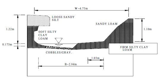
The traditional method adopted for control of erosion potential also does not address the resistance of boundary materials. It assumes the channel is symmetric and the boundary materials are homogeneous (e.g., Enver Creek, Figure 3.1(a)). More typically, channels are asymmetric in form and the boundary materials are heterogeneous deposits (e.g., Serpentine River, Figure 3.1(b)). In the case of Serpentine River, the banks are composed of several different layers of material each of which has unique properties that determine its resistance to erosion. Streams have the tendency to attack the material with the least resistance to erosion. If this material is near the bottom of the bank, the channel will tend to be wider than if the lower materials are more resistant, because the maximum erosive force on the bank is located within the lower third of the bank profile.
Figure 3.1: Channel Forms:
a) Typical Cros -Section Through Reache - Enver Creek
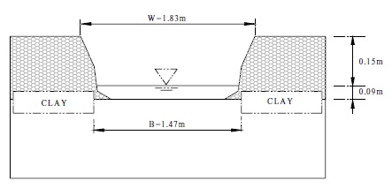
b) Represetative Cross -Section Through Reachf - Serpentine River
The traditional approach to control erosion potential fails to recognize the importance of frequent flow events, the heterogeneity of boundary materials, as well as channel stability. In unstable streams, the innate capacity to absorb a change in the flow regime has been diminished. Consequently, the required degree of control may be greater than for stable systems.
A design methodology that overcomes the limitations of the traditional approach for control of in-stream erosion potential would be preferred. The challenge is to balance the need for a comprehensive characterization of the fluvial system with the need for a relatively simple but universal design procedure that may be applied in circumstances where detailed information may not be available.
3.4.2 Detailed design approach
The Detailed Design Approach may be:
- selected by the proponent for any development regardless of size and location within the watershed provided technical specialists are available for the completion of the technical assessments; or
- considered more appropriate than the simplified approach given the size and location of the development within the watershed and the sensitivity of the receiving waters in terms of morphology and habitat function.
The principal steps involved in the Detailed Design Approach are listed in Table 3.3. A more detailed outline of these steps is provided in Appendix B.
| Step | Description |
|---|---|
| 1 | Clarification of Goals, Objectives and Scope |
| 2 | Resource and Land Use Mapping |
| 3 | Assessment of Channel System
|
| 4 | Stream Stability-Sensitivity Assessment
|
| 5 | Constraint-Opportunity Mapping
|
| 6 | Stormwater Management Alternatives |
| 7 | Design Targets For Control of In-stream Erosion Potential
|
| 8 | Design Criteria For Control of In-stream Erosion Potential
|
| 9 | Selection of Preferred SWM-Stream Restoration Program |
| 10 | Design of Stormwater Management Practices (SWMPs) |
Steps 1, 2, and 3 identified in Table 3.3 represent a desktop level analysis of the channel system to establish the framework for the subsequent investigations. The first element pertains to the definition of long-term goals and objectives for the stream channel. These are often linked to habitat issues. For example, a stream regarded as a valuable fisheries resource, which is currently in a degraded state due to agricultural practices, may be targeted for restoration. The investigations pertaining to channel morphology under this scenario may be different than if the channel system was a small, poorly defined, intermittent stream. Consequently, the identification of likely impacts on stream channel morphology associated with development of the basin is closely linked to habitat targets. The sensitivity of the channel system to a disturbance in the flow-sediment regime and the current morphologic state of the channel system are also significant considerations. If the channel has not been affected by a prior disturbance, this element is relatively straightforward. If the channel has been impacted, additional studies may be required to ascertain the degree of impact, the evolutionary state of the channel and its ultimate form. A checklist to deal with these later investigations is provided in Appendix B.
Step 4 involves the collection of parameters characterizing the channel system that are needed to satisfy the scope of the investigations defined in Steps 1 through 3. A 'like' reach approach has been proposed wherein the channel is divided into reaches of 'like' morphology. This approach assumes that the sensitivity of the channel and its mode of adjustment to a disturbance are similar within reaches having similar morphology. A number of representative cross-sections are selected within distinct reaches to characterize the parameters describing the channel system. These data are used to develop hydraulic parameters and geomorphologic relationships modelling the channel system.
This information is subsequently used in the development and design of the SWM measures and channel restoration programs if required.
Steps 5 through 9 deal with the development, assessment and selection of a preferred SWM alternative. The key elements in this component of the investigation are:
- identification of constraints and opportunities;
- the development of SWM design criteria;
- the development of SWM alternatives consisting of suites of SWMPs;
- selection of a preferred SWM alternative; and
- preliminary design of the SWMPs described in the preferred SWM alternative.
The development of design criteria involves the translation of habitat targets into water quality and quantity specifications. The quantity specifications are related to the types of fluvial features required to meet habitat targets and their stability under the proposed development scenario. For example, the preservation of the benthic macro-invertebrate community of a stream requires a specified particle size distribution for the bed materials within a riffle segment. Secondly, the survival of this community requires that these materials not be mobile over more than some specified time period in any year. The stability of these materials can be determined using critical shear stress concepts wherein the threshold for movement and the duration of exceedance of this threshold represent SWM design criteria.
Once the design targets are specified, lot level and conveyance controls may be investigated and integrated into the preferred SWM alternative. Once the level of control provided by these measures has been established, the active storage volume for end-of-pipe facilities required to meet the design constraints may be approximated. Refinements of the estimate of the active storage volume of the facility may be required until the in-stream erosion targets are closely approximated. Finally the rate of outflow is adjusted until the erosion targets are satisfied.
Rate control may be achieved using various approaches. One approach, Distributed Runoff Control (DRC), is outlined in Appendix D. The focus of this method is the preservation of the balance between the erosive and resisting forces about the channel perimeter such that the stream is just able to move its sediment load. As such, the DRC method incorporates many of the elements described in Section 3.4.1 of this report.
Step 10 concerns the development of the detailed design of the SWMPs described in the preferred SWM alternative. It also involves the development of the Implementation Plan. A key aspect of this Plan is the incorporation of an adaptive management approach. This approach acknowledges that the understanding of stream behaviour is incomplete and that a monitoring program is an essential component of any Implementation Plan. Secondly, the Plan identifies stewardship responsibilities for the channel system and fiscal as well as physical mechanisms for the implementation of adjustment procedures or corrective maintenance.
3.4.3 Simplified design approach
3.4.3.1 Application of simplified design approach
Application of the Simplified Design Approach requires agreement by both the reviewing agency and the proponent of the development.
The Simplified Design Approach may be adopted for watersheds whose development area is generally less than twenty hectares and either one or the other of the following two conditions apply.
A: the catchment area of the receiving channel at the point-of-entry of stormwater drainage from the development is equal to or greater than twenty-five square kilometres; or
B:
- the channel bankfull depth is less than three quarters of a metre;
- the channel is a headwater stream;
- the receiving channel is not designated as an Environmentally Sensitive Area (ESA) or Area of Natural or Scientific Interest (ANSI) and does not provide habitat for a sensitive aquatic species;
- the channel is stable to transitional; and
- the channel is slightly entrenched.
The selection criteria are provided in Table 3.4, and explained below.
| Parameter | Criteria | Comment/Definition |
|---|---|---|
| Subwatershed/Area Plan | n/a | No Area or Subwatershed Plan exists |
| Size of Development | CDADEV ≤ 20 ha | The Catchment Drainage Area of the Development is generally less than or equal to 20 ha |
| Headwater (or First-Order) Stream | 1st | The stream is a first-order channel according to the Horton classification system using 1:50,000 topographic mapping |
| Stability Index Value | SI ≤ 0.4 | The channel is classified as stable or transitional according to the Stability Index value computed using the Rapid Geomorphic Assessment (RGA) form (Appendix C) |
| Entrenchment Ratio | T ≥ 2.2 | The channel is slightly entrenched according to the Rosgen (1996) classification system |
| Bankfull Depth | DBFL < 0.75 m | The bankfull depth is less than 0.75 m in height |
| ANSI/ESA | n/a | The stream is not considered to be an Area of Natural or Scientific Interest, nor part of an Environmentally Significant Area, and does not provide habitat for a sensitive aquatic species |
| Riparian Vegetation | Dense | Riparian Vegetation coverage is dense, covers virtually all of the bank area with a root depth which penetrates to or below the low flow water level |
Subwatershed/Area Plan: If a Subwatershed or Environmental Management Plan already exists for the proposed development area, then these Plans take precedence.
Size of Development: While the Detailed Design Approach represents a more comprehensive method, a simplified approach was considered useful for small developments where detailed environmental data were not already available.
Stream Order: The channel network can be mapped and the channel divided into segments, according to a hierarchy of orders. Each fingertip, or headwater channel, is designated as a segment of the first order. The order increases at the junction of two first-order segments. A stream of higher order implies a stream of greater geomorphic diversity and greater magnitude in dimension. By definition, first-order streams represent those channels having the smallest dimensions within the watershed.
Stability Index Value: A stable stream has an innate ability to absorb a certain amount of change in the sediment-flow regime before the threshold of adjustment is reached. This tolerance is reduced in streams designated as in "transition" or in "adjustment" according to the Rapid Geomorphic Assessment approach (Appendix C). Because a "zero increase" in erosion potential Stability Index Value: A stable stream has an innate ability to absorb a certain amount of change in the sediment-flow regime before the threshold of adjustment is reached. This tolerance is reduced in streams designated as in "transition" or in "adjustment" according to the Rapid Geomorphic Assessment approach (Appendix C). Because a "zero increase" in erosion potential
Entrenchment Ratio: The Entrenchment Ratio provides an indication of the flow conveyance capacity of the active channel. A higher flow conveyance capacity means that flows of higher return period (greater flow rate and volume) will be contained within the active channel. Given the likelihood that flow rate and volume will increase as a consequence of development, this additional conveyance capacity translates into higher in-stream erosion potential. In contrast, a less entrenched channel means that flows of higher return period will spill out over the floodplain thereby dissipating the erosive energy. Consequently, a channel of low entrenchment is preferred.
Bankfull Depth: For bank heights of greater than 0.75 m the characteristics of the soil materials (cohesion, particle size and compaction, stratification, etc.) and the root binding effects of vegetation are generally considered to be the controlling and modifying factors, respectively. For these channel systems a stability analysis based on critical shear stress concepts may be required. For bank heights of less than 0.75 m colonized by dense, herbaceous vegetation, the influence of root binding may become dominant. In first-order tributaries having bankfull widths less than 3 m, channel gradients less than 1.5% and mature, dense woody vegetation, the occurrence of Large Organic Debris (LOD) may also control channel form. Consequently, both biological and pedological (i.e., soil) factors may contribute to channel form in first-order channels.
ANSI/ESA: These designations or any other environmentally significant factors that may be identified may require that the Detailed Design Approach be adopted.
Riparian Vegetation: As noted under "Bankfull Depth" above, riparian cover is an important determinant in boundary material resistance to erosion. Riparian cover must be dense and complete to be effective.
3.4.3.2 Overview of technical steps
The Simplified Design Approach involves three components:
- a synoptic level geomorphic survey of the stream channel to collect measurements of channel form;
- assessment of the applicability of the Simplified Design Approach for the proposed development; and
- determination of the volume of source control and the active storage volume flow rate for an end-of-pipe facility.
These technical steps are described in more detail in Appendix C.
3.5 Water quantity
The increase in direct runoff, together with the rapid conveyance of runoff in urban areas, results in increased peak streamflows, particularly during the summer and fall. Winter and spring runoff may not change dramatically because pre-development runoff may be high due to frozen or saturated soils. In contrast, little runoff occurs during summer and early fall storms under pre- development conditions due to high evapotranspiration and infiltration rates. Further, improved conveyance systems have less effect on the timing of peak streamflows for low intensity, long duration winter and spring storms than for high intensity, short duration summer and early fall storms.
The impacts of increased peak flow rates include increased risks to life and property. Stormwater management must minimize these risks.
3.5.1 Peak flow rate criteria
Generally, accepted criteria are that maximum peak flow rates must not exceed pre-development values for storms with return periods ranging from 2 to 100 years. When measures to address water balance, erosion potential, and water quality are implemented, post-development runoff may be lower than pre-development runoff.
Peak flow rates must be determined on a site by site basis. Existing rates can be determined utilizing computer simulation modelling or by transposing a frequency analysis of measured peak flow rates on a unit area basis (Table 3.2) to a site. The latter approach will be more accurate. Computer simulation modelling will still be required to determine the impact of post- development attenuated runoff on peak flow rates at locations downstream of the site.
| Parameters | Humber River @ Elder Mills 02HC025 | Rouge River near Markham 02HC022 | Don River @ York Mills 02HC005 |
|---|---|---|---|
| Drainage Area, km² | 303 | 186 | 88 |
| 2 Year Peak Flow Rate, m³/s | 35 | 43 | 25 |
| 2 Year Peak Unit Area, m³/s/ha | 0.0040 | 0.0049 | 0.0028 |
| 100 Year Peak Flow Rate, m³/s | 116 | 73 | 119 |
| 100 Year Peak Unit Area, m³/s/ha | 0.0132 | 0.0083 | 0.0135 |
Transposing a frequency analysis of measured flow rates should only be conducted for drainage areas upstream of the flow measurement location. Generally, unit area peak flow rates decline as drainage area increases. Transposition of measured flow rates upstream of the measurement location can be accomplished using computer simulation models.
3.5.2 Potential impacts of attenuated runoff
Controlling post-development peak flow rates through storage to values less than pre- development conditions (overcontrol) may be required to maintain existing downstream watershed peak flow rates. Downstream rates can increase, although site runoff is controlled to pre-development levels. The timing of detained runoff peaks from specific points of a watershed may result in the coincidence of peaks. Providing site storage in the lower or mid portions of a basin will probably increase downstream peak flow rates as attenuated runoff will peak near the same time as upstream runoff. Controlling runoff in the upper portions may reduce downstream peak flow rates as the peaking times are significantly different. The potential impacts of site attenuated runoff on downstream watershed peaks should be calculated on a site by site basis.
3.6 Stormwater management practice selection and integration
As described in Chapter 2, a Subwatershed Study, and the more detailed Environmental Management Plan, provides a preferred environmental and stormwater management strategy including a series of stormwater management practices. Collectively, the practices included in the management strategy can achieve the environmental goals and objectives established for the Subwatershed.
The previous sections of Chapter 3 describe how objectives may be set for water balance maintenance, water quality protection, and control of erosion and flooding, if objectives have not already been established as part of the environmental planning process. The types of stormwater management controls suitable for addressing each issue have also been introduced (e.g., Table 1.3). Typically, a combination of stormwater management practices is required to meet the set of criteria addressing all water resource concerns. Lot level and conveyance controls, specifically the infiltration-based controls, are required to maintain the natural hydrologic cycle to the greatest extent possible. End-of-pipe facilities are usually required for flood and erosion control and water quality improvement, although lot level and conveyance controls can reduce the size of the end-of-pipe facilities required.
Alternative series of stormwater management practices, each meeting all of the established criteria, may be developed. It is worth re-emphasizing that the cumulative impacts of individual developments cannot be explicitly addressed without a Subwatershed Plan.
It should be confirmed that the proposed alternatives are feasible. Physical site constraints may preclude the use of certain stormwater management controls (Table 4.1). For example, native soils with low percolation rates may limit the use of infiltration type controls. There may be municipal standards or by-laws restricting the use of some SWMPs (e.g., reduced lot grading). Detailed design information for each SWMP, including possible constraints to use, is provided in Chapter 4. The integration of individual SWMPs in a Stormwater Management Plan that mitigates the multiple effects of urban development according to the established criteria is also described more fully in Chapter 4.
Footnotes
- footnote[1] Back to paragraph Table 3.2 does not include every available SWMP type. Any SWMP type that can be demonstrated to the approval agencies to meet the required long-term suspended solids removal for the selected protection levels under the conditions of the site is acceptable for water quality objectives. The sizing for these SWMP types is to be determined based on performance results that have been peer-reviewed. The designer and those who review the design should be fully aware of the assumptions and sampling methodologies used in formulating performance predictions and their implications for the design.
- footnote[2] Back to paragraph Hybrid Wet Pond/Wetland systems have 50-60% of their permanent pool volume in deeper portions of the facility (e.g., forebay, wet pond).