6. Annular Space & Sealing
Chapter Description
This chapter covers the construction process involved in sealing the well casing into the hole to ensure that there is no movement of water or other materials along the annular space as required by the Wells Regulation.
Regulatory Requirements - Annular Space & Sealing Of A New Well
Relevant Sections - The Wells Regulation
- Casing – Subsections 13(12) and 13(20)
- Annular Space – Sections 14 and 14.1 to 14.6
The Requirements - Plainly Stated
The Wells Regulation requires the following regarding creation and sealing of the annular space for new well construction:
- Annular space
- means an open space between a casing or well screen and the side of a well, and includes space between overlapping casings within the well
Subsurface Movement for New Well Construction
The person constructing the well must ensure that any annular space, other than the annular space surrounding the well screen, is sealed to prevent any movement of water, natural gas, contaminants or other material between subsurface formations or between subsurface formations and the ground surface by means of the annular space.
Sealing Annular Space for New Wells
See Table 6-1A and Table 6-1B in this chapter for a summary of the requirements outlined in the Wells Regulation that the person constructing the well must follow when creating and filling the annular space for a new well construction other than jetted wells or wells constructed by use of a driven point.
New Wells Constructed by Use of a Driven Point
A person constructing a well by use of a driven point must ensure that any annular space is filled to the ground surface using a method and material approved by the Director (see “Grout Placement – Annular Space for Driven Points” in this chapter).
New Wells Constructed by Jetting
The requirements in Table 6-1A and Table 6-1B do not apply to a new well that is constructed by jetting. The annular space sealing requirements in “Subsurface Movement for New Well Construction” on the previous page apply to a new well constructed by jetting equipment.
Sealing Casing in Bedrock for New Drilled Wells
If the aquifer is located in a bedrock zone that is not weathered, the person constructing the well must ensure that the casing of a new drilled well is sealed into the bedrock with suitable sealant to prevent impairment of the quality of the groundwater and the water in the well.
Reminder: For clarification of the term “weathered bedrock” and “suitable sealant” see Chapter 2: Definitions & Clarifications, Table 2-2.
Sealing Annular Space between Casings
The person constructing the well must ensure that the annular space between casings of different diameters is sealed with suitable sealant to prevent the entry of surface water or other foreign materials into the well.
New Well Completed with a Permanent Outer Casing – Double Walled Casing
Some new wells are completed with a casing surrounded by a permanent casing of larger diameter (i.e., a permanent outer casing). The person constructing the well must ensure that the annular space around and between the inner casing(s) and the permanent outer casing for a new well is sealed, as follows:
- All construction and sealing requirements for the corresponding well construction method in Table 6-1A and Table 6-1B apply with necessary modifications to the well’s annular space on the outside of the outer casing. As a necessary modification, the depth of the annular space must extend from the ground surface to at least the bottom of the permanent outer casing or 6 m (19.7ft), whichever is less unless.
- If any groundwater is entering the annular space between the inner casing(s) and the permanent outer casing, the entire annular space between the casings must be sealed, with necessary modifications, in accordance to the minimum requirements of Table 6-1A and Table 6-1B. This requirement does not apply to a well pit or a well constructed by the use of a driven point.
- In all cases, the annular space between casings of different diameters must be sealed with suitable sealant to prevent the entry of surface water and other foreign materials into the well.
Annular Space below the Permanent Outer Casing
Person Constructing a Well
Although the person constructing a well is not specifically required to seal the casing below the permanent outer casing; the person must do what is necessary as the Ontario Water Resources Act prohibits every person from discharging or causing or permitting the discharge of any material of any kind into any waters that may impair the quality of any waters. This includes prohibiting contaminated groundwater from impairing the quality of other groundwater zones when constructing a well.
Well Owner
Persons using the above professional judgment and the well owner should be aware of the following requirement.
If the well acts as a pathway for the movement of:
- natural gas,
- contaminants, or
- other materials
between subsurface formations (including aquifers) or between the ground surface and a subsurface formation and where the movement may impair the quality of any waters, the person abandoning the well, often the well owner, must to do one of the following:
- take measures to prevent the movement of the above materials and ensure the measures are functional at all times, or
- immediately abandon the well
See Chapter 14: Abandonment: When to Plug & Seal Wells and Chapter 15: Abandonment: How to Plug & Seal Wells of this manual for further information on abandonment.
Reminder: Definitions for sealant, watertight, tremie pipe and other relevant terms are stated in Chapter 2: Definitions & Clarifications.
Reminder: See Figures 6-6 to 6-13 for illustrations of the sealing requirements described in Table 6-1A and Table 6-1B for most common wells.
| Drilled Well or any other Well ≥ 6 m (19.7ft) deep that is not listed on Table 6-1A or B (except jetted wells & wells constructed using driven points) | Drilled Well or any other Well < 6 m (19.7ft) deep that is not listed on Table 6-1A or B (except jetted wells & wells constructed using driven points) | New Well Pit (see Chapter 9: Equipment Installation) | |
|---|---|---|---|
| Minimum Diameter of Hole Greater Than Outer Casing Diameter to Create Annular Space |
|
|
|
| Minimum Diameter of Hole Greater Than Outer Casing Diameter to Create Annular Space |
|
|
|
| Minimum Depth of Annular Space below Ground Surface at the Diameter Specified in the Previous Row |
|
|
|
| Bottom of Filter Pack Material around Well Screen if present |
|
|
|
| Type of Annular Filter Pack Material around Well Screen |
|
|
|
| Maximum Top of Annular Filter Pack Material around Well Screen and Well Casing |
|
|
|
| Annular Seal Material around Casing in remaining Open Annular Space |
|
|
|
| Where Cement Is Used in Suitable Sealant Mixture |
|
|
|
| Bored Well with Concrete Casing ≥ 6 m (19.7ft) deep | Bored Well with Concrete Casing < 6 m (19.7ft) deep | Dug (or Excavated) Well | |
|---|---|---|---|
| Minimum Diameter of Hole Greater than Outer Casing Diameter to Create Annular Space |
|
|
|
| Minimum Diameter of Hole Greater than Outer Casing Diameter to Create Annular Space |
|
|
|
| Minimum Depth of Annular Space below Ground Surface at the Diameter Specified in the Previous Row |
|
|
|
| Bottom of Filter Pack Material around Well Screen if Present |
|
|
|
| Type of Annular Filter Pack, Granular or Native Material |
|
|
|
| Maximum Top of Annular Filter Pack Material around Well Screen and Well Casing |
|
|
|
| Annular Seal Material around Casing in Remaining Open Annular Space from Filter Pack, Granular or Native Material to ≥ 2.5 m (8.2ft) below Ground Surface |
|
|
|
| Annular Seal Material around Casing from ≥ 2.5 m (8.2ft) below Ground Surface to Ground Surface |
|
|
|
| Where Cement is Used in Suitable Sealant Mixture |
|
|
|
Reminder: When mixing, handling or placing any grout material (wet and dry), it is important to always follow manufacturer’s specifications and recommended procedures. It is also important to consult the Material Safety Data Sheet (MSDS) for additional information on safe handling and usage.
- Tremie Pipe
- is a pipe or tube with an inner diameter that is at least three times the diameter of the largest particle of material to pass through it and that is used to conduct material to the bottom of a hole, including a hole containing standing water. For clarification with respect to a tremie pipe, a pipe or tube means a long, hollow (empty space) cylinder.
Well Record - Relevant Sections
Figure 6-1: Well Record - Relevant Sections - Annular Space
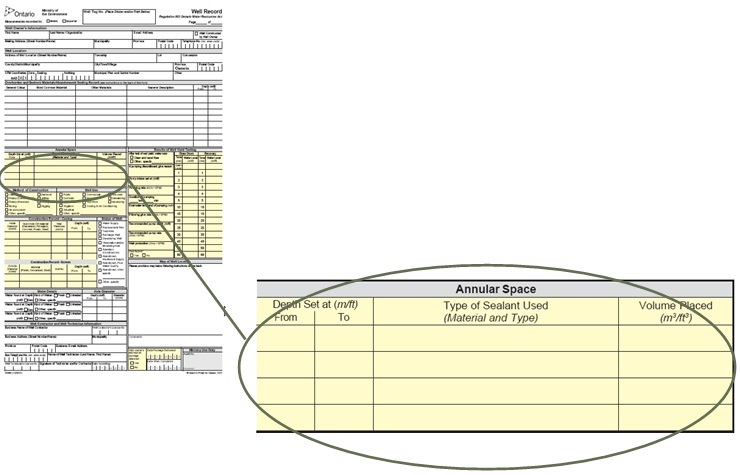
Annular Space
- Depth set at (m/ft) From
- Depth set at (m/ft) To
- Type of Sealant Used (Material and Type)
- Volume placed (m3/ft3)
Notes:
- Record 'Depth Set at' relative to the ground surface
- Record 'Depth Set at' and 'Volume Placed' in the measurement units indicated at the top of the well record (metric or Imperial)
- Calculate 'Volume Placed' using the information found in "Calculating Amount of Materials Required" in this chapter.
Figure 6-2: Well Record - Relevant Sections - Construction Record
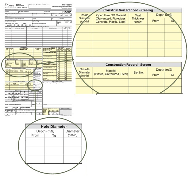
Figure 6-2 shows where the details regarding the construction of the hole and casing the well are to be recorded on the well record.
Construction Record
-
Casing
- Inside Diameter (cm/in)
- Open Hole or Material (Galvanized, Fibreglass, Concrete, Plastic, Steel)
- Wall Thickness (cm/in)
- Depth (m/ft) From
- Depth (m/ft) To
-
Screen
- Outside Diameter (cm/in)
- Material (Galvanized, Plastic, Steel)
- Slot No.
- Depth (m/ft) From
- Depth (m/ft) To
Notes:
- Record the 'Depth' of the well relative to the ground surface
- Record the 'Depth' of the well and 'Wall Thickness' using the measurement units indicated on the top of the record (metric or Imperial)
Hole Diameter
- Depth (m/ft) From
- Depth (m/ft) To
- Diameter (cm/in)
Notes:
- Record the 'Diameter' and 'Depth' of the hole using the measurement units indicated on the top of the record (metric or Imperial)
- Record the 'Depth' of the hole relative to the ground surface
Best Management Practice – Report use of Centralizers
The use of centralizers or breakaway guides and where they are located in the well should be reported on the well record in the “Overburden and Bedrock Materials/Abandonment Sealing Record” section of the Well Record. See Chapter 13: Well Records, Documentation, Reporting & Tagging for the complete well record.
Key Concepts
What To Consider When Sealing The Annular Space
The Annular Space
During construction of a well, an annular space is created when the size of the hole in the ground is larger than the casing and well screen diameter.
Best Management Practice – Annular Space Diameter
An annular space needs to be large enough to ensure sealant will fill and adhere around the entire casing. In most subsurface conditions, the hole diameter should be 102 mm (4 inches) to 203 mm (8 inches) larger than the outer finished casing diameter because it facilitates the use of tremie pipes and the placement of the sealant, and possibly the filter pack, in the annular space.
See Chapter 5: Constructing & Casing the Well for information on creating the hole.
Best Management Practice – Annular Space Depth
A properly sealed annular space running the entire length of the casing stabilizes and improves the overall integrity of the well.
Purpose of the Seal
If a casing is placed into the ground without an annular space, the formation material along the casing becomes loosened and disturbed. The disturbed section along the casing can become a pathway for the migration of contaminants, gas and groundwater.
A properly created and filled annular space around a casing will:
- isolate a discrete zone,
- prevent migration of surface water and other foreign materials into the well and aquifers,
- prevent migration of groundwater or contaminants between water bearing formations and subsurface formations,
- prevent migration of groundwater or contaminants between water bearing formations and the ground surface,
- prevent aquifer depressurization by stopping the upward migration of water along the casing, or
- prevent gas migration.
Examples Of Improperly Sealed Annular Spaces
Figure 6-3: Visible Open Annular Space Adjacent To Drilled Well Casing
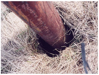
Figure 6-3 shows an annular space that goes from ground surface to the bottom of the casing (not shown) and allows for migration of surface water and other foreign materials into the well and aquifer.
Figure 6-4: Visible Open And Large Annular Space Around Drilled Well
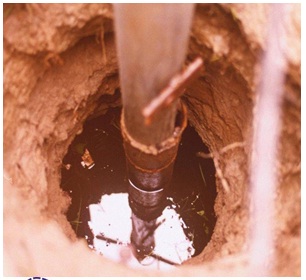
In Figure 6-4, the annular space extends from ground surface, through an upper aquifer and to the bottom of the casing (not shown). The annular space allows for migration of surface water and other foreign materials into the well and aquifers. It also allows contaminated groundwater from this upper aquifer to mix with and impair the waters of a lower aquifer. In this case, the open space also creates a physical hazard.
This photograph also shows the use of casings with differing diameters that appear to be improperly joined.
Figure 6-5: Visible Open Annular Space Below Pitless Adapter And Horizontal Waterline To The Bottom Of The Casing
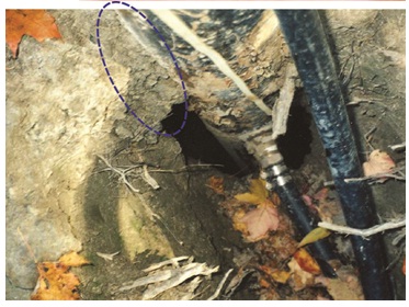
Figure 6-5 shows a visible open space (i.e., annular space) below the pitless adapter and horizontal waterline. The open space extends to the bottom of the casing (not shown in photograph). Above the waterline, the person constructing the well installed a bluish grey coloured bentonite grout in the annular space from above the pitless adapter to the ground surface (see circled area). Thus, no one knew the annular space was improperly filled (or left open) below the pitless adapter until the exterior of the well was excavated. The open space acts as a direct pathway for foreign materials to enter and impair groundwater resources.
Annular Space Sealing Exemptions And Special Cases
The Ontario Water Resources Act prohibits any person from impairing the quality of any waters in Ontario. This section describes regulatory exemptions to the annular space sealing requirements listed in Table 6-1A and Table 6-1B.
These annular space sealing exemptions do not release anyone from complying with the Ontario Water Resources Act general provision regarding the impairment of waters.
The exemption discussed in this section deals with a new well completed with a permanent outer casing - double walled casing.
New Well Completed With A Permanent Outer Casing - Double Walled Casing
In some cases, multiple casings of different diameters are installed in new wells to reach a groundwater zone. This type of installation is common in flowing wells and municipal wells. The annular space around and between the inner casing(s) and the permanent outer casing for a new well must be sealed as follows:
- All construction and sealing requirements for the corresponding well construction method in Table 6-1A and Table 6-1B apply with necessary modifications to the well’s annular space on the outside of the outer casing. As a necessary modification, the depth of the annular space must extend from the ground surface to at least the bottom of the permanent outer casing or 6 m (19.7ft), whichever is less.
- If any groundwater is entering the annular space between the inner casing(s) and the permanent outer casing, the entire annular space between the casings must be sealed, with necessary modifications, in accordance to the minimum requirements of Table 6-1A and Table 6-1B. This requirement does not apply to a well pit or to a well constructed by the use of a driven point.
- In all cases, the annular space between casings of different diameters must be sealed with suitable sealant to prevent the entry of surface water and other foreign materials into the well.
Although the person constructing a well is not specifically required to seal the casing below the permanent outer casing; the person must do what is necessary as the Ontario Water Resources Act prohibits every person from discharging or causing or permitting the discharge of any material of any kind into any waters that may impair the quality of any waters. This includes prohibiting contaminated groundwater from impairing the quality of other groundwater zones when constructing a well.
Persons using the above professional judgement and the well owner should be aware of the following requirement.
The Wells Regulation - If a well acts as a pathway for the movement of:
- natural gas,
- contaminants, or
- other material
between subsurface formations (including aquifers) or between the ground surface and a subsurface formation and where the movement may impair the quality of any waters, the person abandoning the well, often the well owner, must do one of the following:
- take measures to prevent the movement and ensure the measures are functional at all times, or
- immediately abandon the well .
Reminder: See Chapter 14: Abandonment: When to Plug & Seal Wells and Chapter 15: Abandonment: How to Plug & Seal Wells of this manual for further information on well abandonment.
Requirements For Sealing Various Types Of Wells
Figure 6-6 to Figure 6-13 show cross-sectional illustrations and relevant graphics for the construction of various new wells. The figures show the Wells Regulation requirements for minimum hole size, annular space filling products around well screens and suitable sealant in the annular space around the casings.
Reminder: All figures and diagrams are for illustrative purposes only and do not necessarily represent full compliance with other requirements found in the Wells Regulation (e.g., well covering during construction).
Reminder: During and after construction the person constructing the well must ensure surface drainage is such that water will not collect or pond in the vicinity of the well.
Reminder: The person constructing the well must also cover the upper open end of the well securely to prevent entry of surface water and other foreign materials into the well during well construction.
Reminder: For details on the hole, casing and other construction requirements not shown in Figure 6-6 to Figure 6-13, refer to the following chapters in this manual:
- Chapter 5: Constructing & Casing the Well
- Chapter 7: Completing the Well’s Structure
Reminder: Each of the wells shown in Figure 6-6 to Figure 6-13 may encounter conditions that may require specialized design or construction. For example:
- flowing artesian conditions, presence of gas, or
- breathing (sucking and blowing) conditions where the well and aquifer formation are significantly affected by changes in atmospheric pressure.
Therefore the illustrations and graphics may not depict every circumstance.
Figure 6-6: Drilled Well In Overburden - Well Screens That Are Artificially Packed Or Naturally Developed
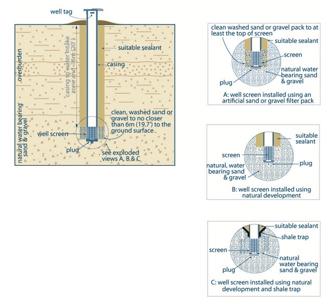
The left side of Figure 6-6 shows a cross-sectional diagram of a drilled well in overburden with a well screen. The bottom of the well is completed with a well screen that is located in a water bearing sand and gravel overburden. A plug is located on the bottom of the well screen. The well screen is attached to the casing. The casing extends vertically from the top of the well screen (the water intake zone) to above the ground surface. There is text adjacent to the casing in the diagram. The text indicates that the casing is required to extend from the ground surface to at least 6 metres (19.7 feet) below the ground surface. The top of the casing is capped with a vermin proof well cap and a well tag is affixed to the outside of the casing above the ground surface. The annular space around the casing is filled with suitable sealant and the annular space around the well screen is filled with cleaned wash sand or gravel. It is a requirement that the clean washed sand and gravel can be no closer than 6 metres (19.7 feet) to the ground surface. The ground surface adjacent to the casing is mounded to prevent the ponding of water in the vicinity of the well.
There is a circle drawn around the bottom of the well that includes the well screen, the overburden near the well screen and the casing just above the well screen. There is text that states “see exploded views A, B and C” with an arrow pointing from the text to the circle.
The right side of Figure 6-6 shows three exploded views (A, B and C).
Exploded View A shows a cross-sectional diagram of a well screen installed using an artificial sand or gravel pack. The diagram shows the bottom of a well completed with a well screen that is located in the natural water bearing sand and gravel overburden. A plug is located on the bottom of the well screen. The well screen is attached to the bottom of the casing. The annular space around the outside of the casing is filled with suitable sealant. The annular space around the outside of the well screen is filled with cleaned wash sand or gravel.
Exploded View B shows a cross-sectional diagram of a well screen installed using natural development. The diagram shows the bottom of a well completed with a well screen that is located in the natural water bearing sand and gravel overburden. A plug is located on the bottom of the well screen. The well screen is attached to the bottom of the casing. The annular space around the outside of the casing is filled with suitable sealant. The overburden has collapsed around the outside of the well screen. The overburden around the well screen is developed to remove fine subsurface material and allow groundwater to enter the well through the well screen.
Exploded View C shows a cross-sectional diagram of a well screen installed using natural development and a shale trap. The diagram shows the bottom of the well completed with a well screen that is located in the natural water bearing sand and gravel overburden. A plug is located on the bottom of the well screen. The well screen is attached to the casing. A shale trap is located around the outside the bottom of the casing. There is an annular space around the outside of the casing and immediately above the shale trap. The annular space around the outside of the casing above the shale trap is filled with suitable sealant. The overburden has collapsed around the outside of the well screen. The overburden around the well screen is developed to remove fine subsurface material and allow groundwater to enter the well through the well screen.
- The hole diameter must be at least 7.6 cm (3 inches) greater than the final outer casing (see A or B) for at least 6 m (19.7ft) from the ground surface or the full depth of the well (which is less).
- If centralizers are used with rotary equipment or a breakaway guide is used with cable tool equipment the hole diameter must be at least 5.1 cm (2 inches) greater than the final outer casing (see C) for at least 6 m (19.7ft) from the ground surface or the full depth of the well (whichever is less).
- When the only useful aquifer necessitates a shallower well, the sand or gravel must not be closer than 2.5 m to the ground surface.
- This applies to all wells other than wells contructed by the use of a driven or jetted point, dug wells and bored wells with concrete casing. This will apply to bored wells with casing other than concrete (e.g. galvanized or fiberglass).
Reminder: See the “Filter Packs around Well Screens for Drilled Wells” section in Chapter 5: Constructing the Hole, Casing & Covering the Well for filter pack material information and best management practices about filter packs.
Reminder: If centralizers are used with rotary equipment or a breakaway guide is used with cable tool equipment, the hole diameter must be at least 5.1 cm (2 inches) greater than the final outer casing for at least 6 m (19.7ft) from the ground surface or the full depth of the well (whichever is less). For additional information, see the “Centering the Casing” section in Chapter 5: Constructing the Hole, Casing & Covering the Well.
Reminder: This figure is not to scale, it is for illustrative purposes for this chapter only, and does not necessarily represent full compliance with other requirements found in the Wells Regulation.
Figure 6-7: Drilled Well - Without Well Screen
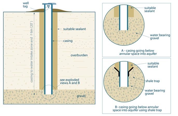
The left side of Figure 6-7 shows a cross-sectional diagram of a drilled well in overburden without using a well screen.
The diagram shows a well completed into gravel overburden. The well is completed with a casing that extends vertically through overburden into a gravel unit. The casing extends from the water intake zone to above the ground surface. There is text adjacent to the casing on the diagram. The text indicates that the casing is required to extend from the ground surface to at least 6 metres (19.7 feet) below the ground surface. A vermin proof well cap is located at the top of the casing and a well tag is affixed to the outside of the casing above the ground surface. The annular space around the outside of the casing is filled with suitable sealant from the ground surface to the top of the gravel. The ground surface adjacent to the casing is mounded to prevent the ponding of water in the vicinity of the well.
There is a circle drawn around the bottom of the well that includes the bottom of the casing and the overburden near the casing on diagram on the left side of Figure 6-7. There is text that states “see exploded views A and B” with an arrow from the text to the circle.
The two exploded views (A and B) are located on the right side of Figure 6-7.
Exploded View A shows a cross-sectional diagram of the bottom portion of the casing driven into an aquifer. The diagram shows the bottom of the well completed with a casing. The bottom of the casing is installed into the water bearing gravel overburden. The annular space located around the outside of the casing above the gravel unit is filled with suitable sealant.
Exploded View B shows a cross-sectional diagram of the bottom portion of the casing driven into an aquifer and a shale trap attached. The diagram shows the bottom of the well completed with a casing. The bottom of the casing is open to the formation. The bottom of the casing is installed into the water bearing gravel unit. A shale trap is located around the outside of the casing and close to the bottom of the casing. The annular space around the outside of the casing and immediately above the shale trap is filled with suitable sealant.
- The hole diameter must be at least 7.6 cm (3 inches) greater than the final outer casing for at least 6 m (19.7ft) from the ground surface or the full depth of the well (whichever is less).
- If centralizers are used with rotary equipment or a breakaway guide is used with cable tool equipment the hole diametermust be at least 5.1 cm (2 inches) greater than the final outer casing for at least 6 m(19.7ft) from the ground surface or the full depth of the well (whichever is less).
- This applies to all wells other than wells constructed by the use of a driven or hetted point, dug wells and bored wells with concrete. This will apply to bored wells with casing other than concrete (e.g. galvanized or fiberglass).
- In this example, the casing has been driven below the bottom of the annular space.
Reminder: If centralizers are used with rotary equipment or a breakaway guide is used with cable tool equipment, the hole diameter must be at least 5.1 cm (2 inches) greater than the final outer casing for at least 6 m (19.7ft) from the ground surface or the full depth of the well (whichever is less). For additional information, see the “Centering the Casing” section in Chapter 5: Constructing the Hole, Casing & Covering the Well.
Reminder: This figure is not to scale, it is for illustrative purposes for this chapter only, and does not necessarily represent full compliance with other requirements found in the Wells Regulation.
Figure 6-8: Examples Of Drilled Wells In Bedrock

Figure 6-8 shows a cross-sectional diagram of three wells (A, B and C) completed in bedrock. The three wells are completed through a layer of overburden underlain by weathered bedrock. The weathered bedrock is underlain by solid (or consolidated) bedrock.
The well on the left of the diagram is example “A”. The well is completed with a casing that extends vertically from above the ground surface through overburden to the top solid bedrock. The bottom of the casing is sealed into the bedrock immediately below the weathered bedrock to prevent impairment of the well water quality in the bedrock. The well is drilled into the solid bedrock as an open hole as the bedrock has enough strength to not collapse into the hole. The well has a vermin proof well cap and has a well tag affixed to the outside of the casing above the ground surface. The ground surface adjacent to the casing is mounded to prevent the ponding of water in the vicinity of the well.
There is an annular space around the outside of the casing from the ground surface to an elevation in the overburden above the top of the weathered bedrock and this annular space is filled with suitable sealant.
The well in the middle of the diagram is example “B” and is considered “better” than example “A”. The well is completed with a casing that extends vertically from above the ground surface through overburden to the top bedrock. A drive shoe (thicker piece of casing) is attached to the bottom of the casing string. The bottom of the casing, with the drive shoe, is sealed and seated at the top of the bedrock immediately below the weathered bedrock. The well is drilled into the solid bedrock as an open hole as the bedrock has enough strength to not collapse into the hole. A vermin proof well cap is located at the top of the casing and a well tag is affixed to the outside of the casing above the ground surface. The ground surface adjacent to the casing is mounded to prevent the ponding of water in the vicinity of the well.
The annular space extending from the ground surface to the weathered bedrock is sealed with a suitable sealant.
The well on the right side of the diagram is example “C” and is considered the “best” of examples “A”, “B” and “C”. The well is completed with a casing that extends vertically from above the ground surface through overburden to and into the solid bedrock. A drive shoe (thicker piece of casing) is attached to the bottom of the casing string. The bottom of the casing, with the drive shoe, is sealed and seated below the top of the solid bedrock. Below the casing, the well is drilled into the solid bedrock as an open hole as the bedrock has enough strength to not collapse into the hole. A vermin proof well cap is located at the top of the casing and a well tag is affixed to the casing above the ground surface. The ground surface adjacent to the casing is mounded to prevent the ponding of water in the vicinity of the well.
The annular space extending from the ground surface to within the solid bedrock, to the bottom of the driveshoe, is sealed with a suitable sealant.
- The hole diameter must be at least 7.6 cm (3 inches) greater than the final outer casing for at least 6 m (19.7ft) from the ground surface or the full depth of the well (whichever is less).
- If centralizers are used with rotary equipment or a breakaway guide is used with cable tool equipment the hole diameter must be at least 5.1 cm (2 inches) greater than the final outer casing for at least 6 m (19.7ft) from the ground surface or the full depth of the well (whichever is less).
- In this example, the casing in A has been driven below the bottom of the annular space so further annular space is created.
Reminder: If centralizers are used with rotary equipment or a breakaway guide is used with cable tool equipment, the hole diameter must be at least 5.1 cm (2 inches) greater than the final outer casing for at least 6 m (19.7ft) from the ground surface or the full depth of the well (whichever is less). For additional information, see the “Centering the Casing” section in Chapter 5: Constructing the Hole, Casing & Covering the Well.
Reminder: This figure is not to scale, it is for illustrative purposes for this chapter only, and does not necessarily represent full compliance with other requirements found in the Wells Regulation.
Figure 6-9: Drilled Well In Overburden-Natural Development, Casing Pulled Back Exposing Screen Method
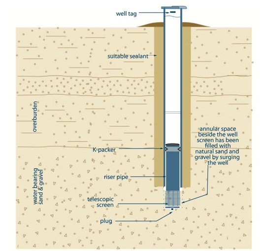
Figure 6-9 shows a cross-sectional diagram of a drilled well in the overburden using natural development, casing pulled back method.
The diagram shows a hole extending vertically into an overburden subsurface. A casing extends from above the ground surface into the hole. The annular space between the outside of the casing and the side of the hole is filled with suitable sealant. A well screen is shown within the bottom of the casing and extends out of the bottom of the casing into the bottom of the hole in the subsurface. The well screen is located in a water bearing sand and gravel. The well screen is made up of a K-packer, riser pipe, screen, coupling and plug. The K-packer is located at the top of the well screen and seals the inner casing and to the outside of the well screen. The riser pipe extends from the K-packer to below the bottom of the casing in the subsurface. The screen is located below the riser pipe in the subsurface. The coupling and plug are located below the screen.
- The hole diameter must be at least 7.6 cm (3 inches) greater than the final outer casing for at least 6 m (19.7ft) from the ground surface or the full depth of the well (whichever is less).
- If centralizers are used rotary equipment or a breakaway guide is used with cable tool equipment the hole diameter must be at least 5.1 cm (2 inches) greater than the final outer casing for at least 6 m (19.7ft) from the ground surface or the full depth of the well (whichever is less)
Reminder: See the “Filter Packs around Well Screens for Drilled Wells” section in Chapter 5: Constructing the Hole, Casing & Covering the Well for filter pack material information and best management practices about filter packs.
Reminder: If centralizers are used with rotary equipment or a breakaway guide is used with cable tool equipment, the hole diameter must be at least 5.1 cm (2 inches) greater than the final outer casing for at least 6 m (19.7ft) from the ground surface or the full depth of the well (whichever is less). For additional information, see the “Centering the Casing” section in Chapter 5: Constructing the Hole, Casing & Covering the Well.
Reminder: This figure is not to scale, it is for illustrative purposes for this chapter only, and does not necessarily represent full compliance with other requirements found in the Wells Regulation.
Figure 6-10: Bored Well With Concrete Casing
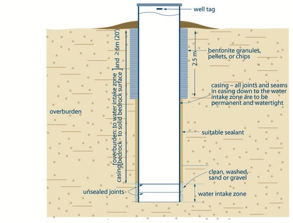
Figure 6-10 shows a cross-sectional diagram of a bored well with concrete casing completed into overburden.
The bored well consists of concrete tiles, arranged vertically on top of one another, from above the ground surface into an aquifer in the overburden. The joints and seams in the concrete tiles are required to be permanently watertight to the water intake zone. These concrete tiles with sealed joints are considered casing. The diagram shows two concrete tiles in the water intake zone that are unsealed. There is text adjacent to the casing on the diagram. The text indicates that the casing is required to extend from the ground surface to at least 6 metres (19.7 feet) below the ground surface. If the well extends into the bedrock, the casing is required to extend to the competent bedrock surface. A well cover is located at the top of the casing and a well tag is affixed to the outside of the casing above the ground surface. The ground surface adjacent to the casing is mounded to prevent the ponding of water in the vicinity of the well.
There is an annular space around the concrete tiles. In the water intake zone, the annular space is filled with cleaned, washed, sand or gravel. From the water intake zone to 2.5 metres (8.2 feet) below the ground surface, the annular space is filled with suitable sealant. From the ground surface to 2.5 metres (8.2 metres) below the ground surface, the annular space is filled with bentonite granules, pellets or chips. There is an annular space around the well screen that is filled with cleaned wash sand or gravel. The clean washed sand and gravel can be no closer than 6 metres (19.7 feet) to the ground surface.
- All concrete tiles with joints that are not sealed with mastic are considered a well screen (water intake zone).
- The hole diameter must be at least 15.2 cm (6 inches) greater than the casing’s outer diameter from the land surface to a depth of 2.5 m (8.2 ft).
- The hole diameter must be at least 7.6 cm (3 inches) greater than casing’s outer diameter from 2.5 m (8.2 ft) to at least 6 m (20ft) below the land surface.
- Sand or gravel must be installed from at least the top of the water intake zone or screen to no closer than 6 m (20ft) below the land surface unless the only useful aquifer available necessitates a shallower well in which case clean, washed sand or gravel must be installed no closer than 2.5 m (8.2 ft) from the land surface.
Reminder: See “Well Screens Using Large Diameter Concrete Tiles” section in Chapter 5: Constructing the Hole, Casing & Covering the Well for information and best management practices on using concrete tiles as well screens.
Reminder: See the “Filter Packs around Well Screens for Drilled Wells” section in Chapter 5: Constructing the Hole, Casing & Covering the Well for filter pack material information and best management practices about filter packs.
Reminder: This figure is not to scale, it is for illustrative purposes for this chapter only, and does not necessarily represent full compliance with other requirements found in the Wells Regulation.
Figure 6-11: Dug Well
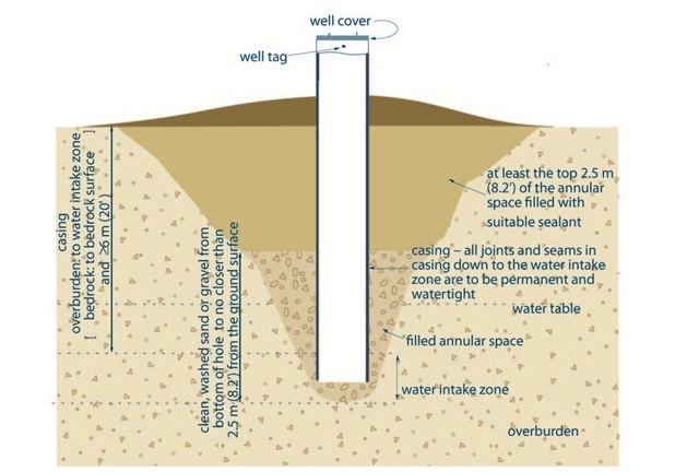
Figure 6-11 shows a cross-sectional diagram of dug well.
The diagram shows a dug well completed into overburden. The well consists of casing that extends vertically from above the ground surface to below the water table in the overburden. The joints and seams in the casing are required to be permanently watertight to the water intake zone. The diagram shows an unsealed joint between two pieces of casing in the water intake zone. The bottom of the casing is open to the formation. There is text adjacent to the casing on the diagram. The text indicates that the casing is required to extend from the ground surface to at least 6 metres (19.7 feet) below the ground surface. The text also indicates that if the well extends into the bedrock, the casing is required to extend to the competent bedrock surface. A well cover is located at the top of the casing and a well tag is affixed to the outside of the casing above the ground surface. The ground surface adjacent to the casing is mounded to prevent the ponding of water in the vicinity of the well.
The area below the casing is filled with clean, washed sand or gravel. There is an annular space around the outside of the casing. The annular space from the bottom of the casing to 2.5 metres (8.2 feet) below the ground surface is filled with clean, washed sand or gravel. From the ground surface to 2.5 metres (8.2 feet) below the ground surface, the annular space is filled with suitable sealant.
- All concrete tiles with joints that are not sealed are considered well screens (water intake zone).
- Sand or gravel can be replaced with native material (soil) that was excavated from the hole, of the well is not constructed in a contaminated area and the horizons of soil are excavated separately, stored separately, kept free from contamination and backfilled in the same relative positions that they originally occupied.
- Suitable sealant that is used to fill annular space must provide appropriate structural strength to support the weight of persons and vehicles that may move over the well area after it is filled.
Reminder: See “Well Screens Using Large Diameter Concrete Tiles” section in Chapter 5: Constructing & Casing the Well for information and best management practices on using concrete tiles as well screens.
Reminder: This figure is not to scale, it is for illustrative purposes for this chapter only, and does not necessarily represent full compliance with other requirements found in the Wells Regulation.
Figure 6-12: Driven Point Well
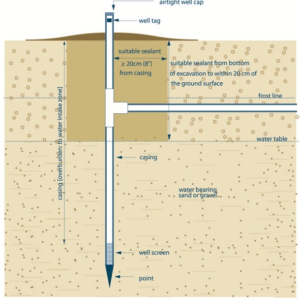
Figure 6-12 shows a cross-sectional diagram of driven-point well.
The diagram shows a driven-point well completed into into an overburden aquifer. The well consists of casing that extends vertically from above the ground surface to into the water table. A well screen is attached to the bottom of the casing and a drive-point is attached to the bottom of the well screen. Below the frost line in the subsurface a horizontal water line connects to the casing. An excavation zone, created to connect the horizontal waterline to the casing, is filled with suitable sealant from the casing to at least 20 centimetres (8 inches) from the casing and from the bottom of the excavation to at least 20 centimetres (8 inches) from the ground surface. An airtight, well cap is located at the top of the casing and a well tag is affixed to the outside of the casing above the ground surface. The ground surface adjacent to the casing is mounded to prevent the ponding of water in the vicinity of the well.
- The excavation has been created as a result of installing pumping equipment. To see how this is filled see Chapter 9: Equipment Installation, for further instructions.
- If any annular space is created during the driving of the casing, the annular space must be completely filled using materials and a method approved in writing by the Director.
Reminder: The diagram above is not to scale and is for illustrative purposes for this chapter only, and does not necessarily represent full compliance with other requirements found in the Wells Regulation.
Figure 6-13: Jetted Well
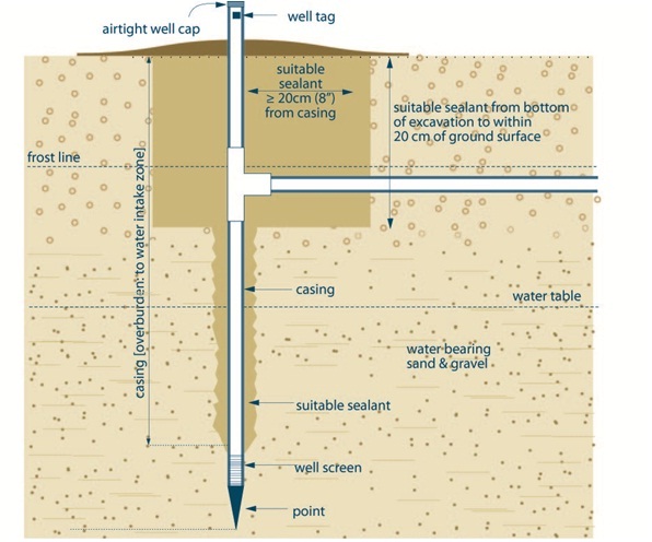
Figure 6-13 shows a cross-sectional diagram of a jetted point well.
The diagram shows a jetted point well completed into an overburden aquifer. The well consists of casing that extends vertically from above the ground surface to within the water table. A well screen is attached to the bottom of the casing and a drive-point is attached to the bottom of the well screen. An excavation zone, created to connect the horizontal waterline to the casing, is filled with suitable sealant from the casing to at least 20 centimetres (8 inches) from the casing and from the bottom of the excavation to at least 20 centimetres (8 inches) from the ground surface. The annular space located between the casing and the side of the hole extending from the screen to the excavation area is sealed with suitable sealant. An airtight well cap is located at the top of the casing and a well tag is affixed to the casing above the ground surface. The ground surface adjacent to the casing is mounded to prevent the ponding of water in the vicinity of the well.
Below the frost line in the subsurface a horizontal water line connects to the casing.
- The excavation has been created as a result of installing pumping equipment. To see how this is filled see Chapter 9: Equipment Installation, for further instructions.
- A person constructing a well by jetting typically creates an annular space around the well casing. The person constructing a well by jetting must ensure that any annular space around a well casing is sealed to prevent any movement of water, natural gas, contaminants, or other material between subsurface formations (aquifers) or between a subsurface formation and the ground surface.
Reminder: The diagram above is not to scale and is for illustrative purposes for this chapter only, and does not necessarily represent full compliance with other requirements found in the Wells Regulation.
Comparision Of Bentonite And Cement Grouts
The most common sealing materials used to seal annular spaces are bentonite and neat cement products. Each have specific, unique and desirable properties. Table 6-2 summarizes the advantages, disadvantages and application of bentonite based sealants (grouts) versus cement based sealants (grouts).
| Sealant | Advantages | Disadvantages |
|---|---|---|
| Bentonite Based Sealants |
|
|
| Cement Based Sealants |
|
|
Notes Regarding Table 6-2
Reminder: Suitable sealant must be compatible with the quality of the water in the well.
Reminder: Sealant must be a bentonite mixture of clean water and at least 20% solids by weight, or a product that will be equivalent with respect to the ability to form a permanent watertight barrier. For example, a mixture of water with cement, concrete or cement with no more than 5% bentonite solids by weight may be an equivalent sealant in some environments.
Reminder: When evaluating bentonite as an annular sealant, consider the following:
- The position of the static water level and its seasonal fluctuations
- The ambient groundwater and mixing water quality
Reminder: In some cases 3 to 8% of bentonite is used as an additive to cement or concrete to improve the workability, slurry weight and density of the cement slurry. This may make it easier to pump or pour the material down a narrow tremie pipe or space. However, bentonite is chemically incompatible with cement and will not swell when mixed with cement. The bentonite additive also reduces the set strength of the seal and lengthens set time
Definitions for sealant, bentonite, watertight, tremie pipe and other relevant terms are provided in Chapter 2: Definitions & Clarifications.
Dry Bentonite Products
Bentonite is manufactured in various forms such as powder, granules, pellets and chips. In some cases, bentonite granules, pellets or chips can be used as a suitable sealant to fill the well’s annular space. See the “Grout Placement – Pouring Bentonite Chips and Pellets from Surface” section in this chapter for further information on the placement of dry bentonite into a well’s annular space. Table 6-3 provides information on the forms of manufactured bentonite.
| Product | Description | Typical Size | Hydration Characteristics |
|---|---|---|---|
| Powder |
|
|
|
| Granules |
|
|
|
| Pellets |
|
|
|
| Chips |
|
|
|
Reminder: Some literature indicates that coated bentonite pellets hydrate more slowly than bentonite chips. Other literature indicates that bentonite chips hydrate more slowly than coated bentonite pellets. A person using a bentonite product should always follow the manufacturer’s specifications for the use and placement of the bentonite product.
Calculating Amount Of Materials Required
Before beginning well construction, the amount of materials (sand, gravel and bentonite and/or cement) required to properly seal the annular space should be calculated. Regardless of the base materials or type of grout, it is the measured amount of water and the consistent use of that ratio of water to the dry product that is the key element to achieving the appropriate grout properties.
The amount of material needed will depend on the volume of annular space that needs to be filled (i.e., width of the annular space and depth of the annular space).
Some things to remember when calculating the amount of materials required:
- The person constructing the well should allow for possible hole increases due to drilling actions, geology and flushing media. Adding 10% to 15% more material to the calculated amount should be considered.
- The volume of the hole that the casing will occupy should be accounted for.
The following formulae can be used to calculate the volume of the annular space.
Method 1
Annular Space Volume = Volume Of Hole − Volume Of Casing, Where:
Volume Of Hole = 3.14 × (Diameter Of Hole ⁄ 2)2 × Depth
And
Volume Of Casing = 3.14 × (Outer Diameter Of Casing ⁄ 2)2 × Depth:
Or
Volume Of Hole = 0.785 × Diameter2 × Depth Of Hole
And
Volume Of Casing = 0.785 × Diameter2 × Depth Of Hole
Method 2
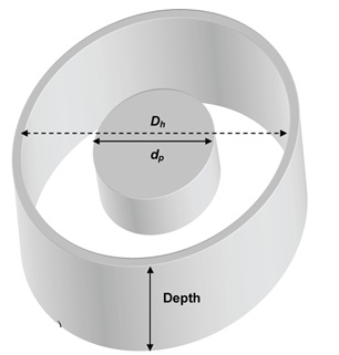
Where:
- Dh
- Diameter of Hole (mm or inches)
- dc
- Outer diameter of casing (e.g. pipe)(mm or inches)
{[Dh(mm)2 − dc(mm)2] ⁄ 1273} × Depth (metres) = Annular Space Volume (Litres)
Or
{[Dh(inches)2 − dc(inches)2] ⁄ 29.45} × Depth (feet) = Annular Space Volume (Imperial Gallons)
Reminder: The exact amount of grout (sealant) required cannot always be determined due to irregularities in the size of the hole and losses into fractured rock. Be prepared with extra material onsite to add to the initial estimate if needed.
Reminder: See the “Tools for Annular Space Sealing” section at the end of this chapter for a Grouts (sealants) application matrix to help calculate the amount of grout required to fill the annular space.
The following tables can be used to calculate the volume of sealant (i.e., bentonite, cement, concrete) yielded per bag of product.
| Volume | 15% Solids Grout | 20% Solids Grout | 23% Solids Grout |
|---|---|---|---|
| Water – Litres | 125 | 91 | 76 |
| Water – Imperial Gallons | 28 | 20 | 17 |
| Yield Volume - Litres | 133.6 | 99.6 | 84.4 |
| Yield Volume – Imperial Gallons | 29.4 | 21.9 | 18.6 |
Reminder: The volumes are calculated using the instructions and information on the package or provided by the manufacturer. Different percentages of bentonite slurry are used for various applications when drilling or sealing.
| Volume | Concrete | Portland Cement |
|---|---|---|
| Water – Litres | 19.7 | 19.7 |
| Water – Imperial Gallons | 4.3 | 4.3 |
| Yield Volume – Litres | 60.3 | 33.3 |
| Yield Volume – Imperial Gallons | 13.3 | 7.3 |
Reminder: Table 6-5 is based on one, 43 kilogram (94 pound) bag of cement. The volume of concrete is based on one, 43 kilogram (94 pound) bag of cement mixed with 0.027 cubic metres (1 cubic foot) of sand or gravel. The volumes are calculated by using the instructions and information on the package or directly from the manufacturer.
Reminder: One litre of water weighs one kilogram and Portland cement produces a slurry weight of 1.87 kg/L. The volumes are calculated using the instructions and information on the package or provided by the manufacturer.
Mixing Bentonite Grout (Sealant)
When mixing grout, it is important to follow the manufacturer’s specifications provided on the packaging or with the product.
Inhibited bentonite grouts (sealants) are a powdered type material that is designed to slow the rate of hydration just long enough to allow the bentonite to be placed into the annular space.
Best Management Practice – Mixing and Placing Bentonite Grout
When mixing bentonite material with clean water, it is important to use a high shear paddle mixer in a mixing drum to thoroughly shear
Positive displacement pumps with minimal shearing action are needed when placing bentonite grout (sealant) in the annular space. This technique allows for proper placement and hydration of the bentonite grout (sealant) in the annular space.
Techniques For Successful Mixing
To ensure that the bentonite sealant will last the life of the well, bentonite must be mixed with clean water. “Clean,” in this context, means water that will not interfere with the reaction to make a bentonite slurry as recommended by the manufacturer and will not impair the water in and around the well.
Best Management Practice – Techniques for Successful Mixing of Bentonite Grout (Sealant)
The following should be considered when mixing bentonite grouts:
- Potable water sources (municipal water, etc.) should not be assumed to be acceptable mixing water for bentonite drilling mud or sealant. Mixing water should always be tested for pH, hardness, total dissolved solids and chlorides before mixing. If available, water quality reports can be reviewed in place of testing the mixing water.
- Bentonite should be mixed with clean water until suspension is achieved. The material should then be immediately pumped into the annular space through a tremie pipe.
- Small batches should be prepared to ensure that at a mixture of least 20% bentonite solids by weight is maintained.
- Gear pumps are better suited for bentonite sealants consisting of bentonite polymer and water mixtures (two step grouts).
- Progressing cavity pumps are better suited for bentonite sealants consisting of bentonite and water mixtures (one step grouts).
Consequences Of Poorly Mixed Bentonite Grout
Mixing water that is not clean (e.g., highly mineralized water), may inhibit the hydration process of the bentonite grout and its effectiveness as a sealant.
If excess “hardness” is present in the mixing water, the polymers and/or bentonite may clump and adhere to the paddles during the mixing phase. In severe cases it can result in plugging of tremie lines and disruption of the grouting process.
Grout that is mixed or sheared too much will start to hydrate too rapidly. This will result in difficulty pumping the grout, plugging up of the tremie line, and wasting a batch.
Reminder: The person constructing the well should follow the manufacturer’s specifications for pH, hardness, chloride, total dissolved solids and other water quality issues (see Table 6-2 for further information on water chemistry and its potential effect on bentonite).
Mixing Cement Or Concrete Grout (Sealant)
Cement grout (sealant) must be made using carefully measured quantities of water and Portland cement (see Table 6-4). In concrete grout, aggregate and other materials (e.g., plasticizers) are added to cement and water. Further information on cement can be found at the Portland Cement Association website titled “Cement and Concrete Basics”.
A paddle mixer in a mixing drum with either a progressive cavity or gear pump is a common choice for mixing and pumping cement or concrete grout (sealant). Small portable grouting machines that combine both the mixing and the pumping operations are also often used. These machines typically have a positive displacement pump because it can work efficiently against much greater head pressures with low loss of grout volume.
Techniques For Successful Mixingfootnote 5
Best Management Practice – Techniques for Successful Mixing
The following should be considered when mixing cement or concrete grouts:
- The mixing water needs to be cool, clean, fresh water free of oil soluble chemicals, organic material, alkalies and other contaminants and have a total dissolved solids concentration of less than 500 mg/L
footnote 6 to ensure proper setting of the grout (sealant). - It is important that grout be mixed thoroughly and ensure it is free of lumps.
- If the mixture is purchased from a ready-mix concrete plant, the correct proportions of cement, water and other aggregate material, if present, should be verified by using equipment such as a drilling fluid balance.
- It is important to use a protective strainer on the tank from which the grout is pumped into the well’s annular space through a tremie pipe.
- The material should be immediately pumped into the annular space through a tremie pipe.
Consequences Of Poorly Mixed Cement Grout
Mixing water that has a high pH or high level of total dissolved solids may result in increased setting times (i.e., slow hydration) and/or failure to set. See Table 6-2 for further information on water chemistry and its potential affect on cement.
If the grout is not thoroughly mixed and free of lumps then partial setting may occur and the effectiveness of the seal will be compromised.
Premature setting may occur due to an incorrect estimate of the hole temperature, the use of hot mixing water, improper water to cement ratios, contaminants in the mixing water, mechanical failures, and interruptions to pumping operations.
Improper water to cement ratios may also cause excessive shrinkage of the grout.
Grout Placement Requirements
The Wells Regulation has specific requirements for the placement of materials in the annular space for new wells (see Table 6-1A and Table 6-1B in the “Requirements Plainly Stated” section of this chapter).
The Wells Regulation requires that any annular space of any new cased well, other than the annular space surrounding the well screen, must be sealed to prevent any movement of water, natural gas, contaminants or other material between subsurface formations or between subsurface formations and the ground surface by means of the annular space. This requirement does not apply to the annular space around an inner casing where a new well has been constructed with a permanent outer casing (see the “New Well Completed with a Permanent Outer Casing – Double Walled Casing” section of this chapter)
For new cased wells, the Wells Regulation requires that
- a tremie pipe be used to install the suitable sealant.
- the bottom of the tremie pipe remain immersed in the rising accumulation of sealant.
This tremie pipe requirement does not apply for new dug wells, wells constructed with the use of a driven point and wells constructed by jetting.
Successful placement of the grout will depend on the temperature, stability, size of the annular space and pressure in the hole, and how well the casing is centered, and the grouting placement. The following best management practice on sealing the annular space provides suggestions to help achieve a successful seal.
Best Management Practice – Sealing the Annular Space
The following will help ensure that the sealant will provide a satisfactory seal:
- During placement of sealant, the sealant returning to the surface should be of the same consistency of that being pumped.
- The first indication of sealant returning to surface is not an indication to stop pumping.
- Where the tremie pipe is placed in the annular space, active pumping of the sealant should continue as the tremie pipe is extracted from the annular space to ensure effective displacement.
- Sealant pump suction and discharge hoses should be adequately sized to overcome friction losses and decrease chances of plugging.
- Suction and discharge hose connections to the pump should be made using quick-connect style couplings. This will save time when attempting to locate a blockage in the hose and allow faster cleanup.
- When the pump is also used for mixing, the discharge hose should be plumbed in such a manner to allow changeover from mixing to pumping sealant without shutting down the pump.
- A pressure gauge should be installed on the pump discharge and monitored to ensure that the working pressure does not exceed the hose and pipe maximum pressure rating. A sudden increase in pressure may indicate that the tremie pipe has become plugged.
Sealant (Grout) Placement Techniques
The following sections provide different techniques used to place suitable sealant into an annular space.
Grout Placement - Inner String Method
In the inner string method of placing grout, the tremie is suspended in the casing. A cementing (float) shoe is attached to the bottom of the casing before the casing is placed in the hole. The tremie pipe is lowered until it engages the shoe.
Placing Grout Using the Inner String Method
To place grout using the inner string method:
- A float shoe or other similar device is attached to the bottom of the casing before the casing is placed in the hole.
- The casing is placed in the hole to the bottom of the well. Then the tremie pipe is lowered inside the casing until it engages the shoe. This permits the grout to pass into the annular space but prevents it from leaking back into the casing while pumping the grout.
- Water or drilling fluid is placed into the casing to prevent the grout from coming back up the casing.
Reminder: For shorter strings of casing [i.e., 6 to 30 metres (20ft to 100ft)], the tremie pipe is sealed at the top of the casing using one or two stacked top well seals. The barrier created by the well seals along with the weight of the drilling fluid or water will minimize the amount of grout that can travel back up the inside of the casing string during and after the pumping process.
- The grout is pumped through the tremie pipe and float shoe and is forced upward around the casing.
- The tremie pipe is disconnected and removed.
- All of the grouting equipment is cleaned.
-
- Where bentonite grout is used and before further well construction proceeds, the bentonite should be allowed time to achieve gel strength. Bentonite takes 8 to 48 hours to achieve full gel strength.
Best Management Practice – Topping Up Settled Bentonite Grout
The bentonite grout should be topped up to the original level before drilling continues if there has been settling or subsidence in the annular space.
- The Wells Regulation - Where cement grout is used, cement must be allowed to set according to manufacturer’s specifications, or 12 hours, whichever is longer. If there has been settling or subsidence in the annular space, the cement grout must be topped up to the original level before drilling continues.
- Where bentonite grout is used and before further well construction proceeds, the bentonite should be allowed time to achieve gel strength. Bentonite takes 8 to 48 hours to achieve full gel strength.
- The float shoe or other device is drilled out or removed from the bottom of the casing.
Reminder: The sealant at the bottom of the casing is susceptible to damage when drilling restarts. The sealant must be physically and structurally sound and capable of withstanding the initial pressures of drilling. After the placement of grout, it is important to prevent flushing media from pushing up and exerting pressure on the grout column when drilling resumes. This upward pressure can be caused by the displacement of water in the casing when using the percussion drilling action or when using air or water based flushing media.
Figure 6-14: Pumping Grout Down Tremie Pipe - Inside Casing
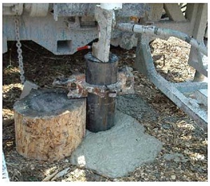
Figure 6-14 shows a steel casing extending out of the ground behind a drill rig. A clamp has been placed around the casing and above a wooden stump to hold the casing in place. A hose from a grout pump (not shown) is attached to a tremie line above the well casing and hidden behind a steel plate. A bentonite grout (suitable sealant) is being forced down the tremie pipe inside the well casing. The grout is being pushed out below the casing and is being forced up the annular space. The benontite grout is seen coming out of the annular space onto the ground surface around the casing.
Figure 6-15: Inner String Method Of Grout Placement
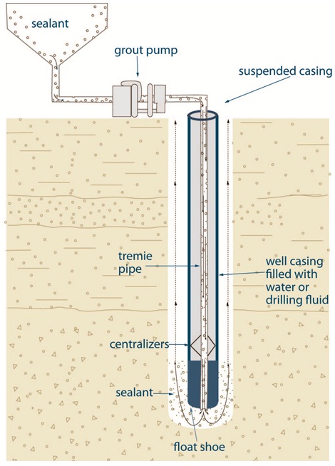
Figure 6-15 shows a cross-sectional diagram of the inner string method to place grout (sealant) into a well.
The diagram shows a vertical hole that extends into the subsurface. A suspended casing has been placed into the hole from above the ground surface to just above the bottom of the hole. A float shoe has been installed at the bottom portion of the casing. A tremie pipe is inserted within the casing and through the float shoe. Centralizers have been installed between the outside of the tremie pipe and the inside of the casing.
An annular space is located between the outside of the casing to the side of the hole. Above the ground surface, a horizontal tremie pipe is attached to the vertical tremie pipe. The horizontal tremie pipe is attached to a grout pump. Another horizontal pipe is attached to the grout pump and a vertical pipe. The vertical pipe is attached to a hopper that contains sealant.
There are arrows and small circles in the diagram demonstrating the flow of sealant through the hopper, horizontal tremie pipe, grout pump and vertical tremie pipe and discharging out of the bottom of the tremie pipe into the bottom of the hole. The arrows are also demonstrating the sealant is being forced upward in the annular space from the bottom of the hole to the ground surface.
Reminder: This figure is not to scale, it is for illustrative purposes for this chapter only, and does not necessarily represent full compliance with other requirements found in the Wells Regulation.
Grout Placement - Tremie Pipe Outside Casing Method
When using this placement method, the grout material is pumped or placed using a tremie pipe that is installed in the annular space.
Best Management Practice – Use of a Grout Pump
When a grout pump is used with a tremie pipe, any fluid (i.e., drilling mud or water) of less weight than the grout will be displaced from the annular space. This technique assists in the proper filling of any voids or spaces with grout (sealant).
Best Management Practice – Use of a Larger Diameter Tremie Pipe
The use as large a tremie pipe:
- reduces the amount of friction loss that is associated with a small diameter tremie pipe,
- reduces the velocity of grout entering the annular space,
- enhances the efficiency of the displacement process and
- significantly improves the effectiveness of the overall seal.
Reminder: The annular space must meet regulatory requirements (see Table 5-5 of and Table 6-1 of this chapter) and be large enough to accommodate the tremie pipe (see Chapter 5: Constructing the Hole, Casing and Covering the Well; “Best Management Practice: Size of Hole”).
Placing Grout Using the Outside Casing Method
To place grout using the tremie pipe outside the casing:
- The lower end of the casing is closed with a drillable plug to ensure the grout that is placed in the annular space cannot enter the casing.
Another option is to drive the casing into the undisturbed formation below the hole.
- The tremie pipe is installed into the annular space. The person constructing the well must ensure that the tremie pipe reaches the bottom of the annular space.
-
- If a pump is used, the grout is pumped down the tremie pipe discharging into the bottom annular space. Continued discharge of grout into the bottom of the annular space causes the rising accumulation of grout to reach the ground surface.
The pump must be capable of developing enough pressure to overcome the friction caused by moving the grout through the tremie pipe and up the annular space.
Issues with a grout pressure head that may prevent the upward placement of grout with a pump are not usually a concern since the grout that is rising to the ground surface is at or below the grout pump elevation.
In some circumstances, it may be advisable to pull the tremie pipe at about the same rate that grout is filling the annular space after the first mixed batch of grout is pumped into the annular space. This will minimize the grout pressure head on the tremie pipe outlet and reduce any chances of the tremie pipe being stuck in the hole due to hydration of the grout.
- If a pump is not used, the grout is poured down a tremie pipe above the ground surface. The grout flows from the tremie pipe into the bottom annular space by the force of gravity. The tremie pipe is raised slowly and the bottom of the tremie pipe remains in the rising accumulation of the grout until the grout reaches the ground surface.
The Wells Regulation - The bottom of the tremie pipe must remain submerged in the rising accumulation of grout until placement of the grout is complete.
- If a pump is used, the grout is pumped down the tremie pipe discharging into the bottom annular space. Continued discharge of grout into the bottom of the annular space causes the rising accumulation of grout to reach the ground surface.
- Grouting may be complete when the grout leaving the annular space at the ground surface is of the same consistency as the grout being introduced into the bottom of the annular space.
- The tremie pipe is disconnect and removed.
- All grouting equipment is cleaned.
-
- Where bentonite grout is used and before further well construction proceeds, the bentonite should be allowed time to achieve gel strength. Bentonite takes 8 to 48 hours to achieve full gel strength.
Best Management Practice – Topping up Settled Bentonite Grout
The bentonite grout should be topped up to the original level before drilling continues if there has been settling or subsidence in the annular space.
- Where cement grout is used, cement must be allowed to set according to manufacturer’s specifications, or 12 hours, whichever is longer. If there has been settling or subsidence in the annular space, the cement grout must be topped up to the original level before drilling continues.
- Where bentonite grout is used and before further well construction proceeds, the bentonite should be allowed time to achieve gel strength. Bentonite takes 8 to 48 hours to achieve full gel strength.
- The plug is drilled out or removed from the bottom of the casing.
Reminder: The sealant at the bottom of the casing is susceptible to damage when drilling restarts. The sealant must be physically and structurally sound and capable of withstanding the initial pressures of drilling. After the placement of grout, it is important to prevent flushing media from pushing up and exerting pressure on the grout column when drilling resumes. This upward pressure can be caused by the displacement of water in the casing when using percussion drilling action or when using air or water based flushing media.
Figure 6-16: Outside Casing Method Of Grout Placement
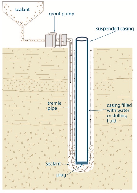
Figure 6-16 shows a cross-sectional diagram of the outside casing method to place grout (sealant) into a well.
The diagram shows a vertical hole that extends into the subsurface. A suspended casing has been placed into the hole from above the ground surface to just above the bottom of the hole. A plug has been placed at the bottom of the casing. An annular space is located from the outside of the casing to the side of the hole. A vertical tremie pipe has been installed inside the annular space, located to the left of the casing, from above the ground surface to the bottom of the casing.
Above the ground surface, a horizontal tremie pipe is attached to the vertical tremie pipe. The horizontal tremie pipe is attached to a grout pump. Another horizontal pipe is attached to the grout pump and a vertical pipe. The vertical pipe is attached to a hopper that contains sealant.
There are arrows and small circles in the diagram demonstrating the flow of sealant through the hopper, horizontal tremie pipe, grout pump and vertical tremie pipe and discharging out of the bottom of the tremie pipe into the bottom of the hole. The arrows are also demonstrating the sealant is being forced upward in the annular space from the bottom of the hole to the ground surface.
Reminder: This figure is not to scale, it is for illustrative purposes for this chapter only, and does not necessarily represent full compliance with other requirements found in the Wells Regulation.
Figure 6-17: Installing Tremie Pipe Outside Casing
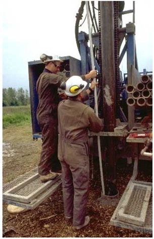
Figure 6-17 shows a tremie pipe being installed in the annular space of a drilled well. The permanent steel casing is being held in place by the drilling rig. A larger diameter starter (or temporary) casing has been installed during the drilling of the hole. The difference in diameter between the two casings has created an annular space large enough to allow for the placement of the tremie pipe.
Figure 6-18: Tremie Remains In Hole During Grout Placement
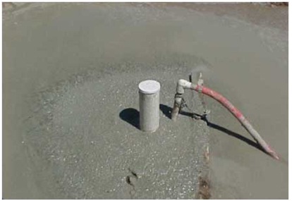
Figure 6-18 shows the tremie pipe remaining in the annular space while grout is being pumped through it to fill the entire annular space. In some cases, the tremie pipe may need to be raised during pumping to ensure the tremie pipe does not get stuck in the curing sealant.
Figure 6-19: A Successful Seal
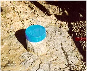
Figure 6-19 shows a suitable sealant that has been placed in the annular space along the casing and up to the ground surface.
Figure 6-20: Example of a Properly Sealed Annular Space
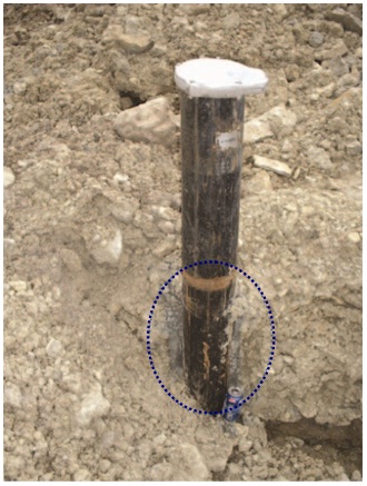
Figure 6-20 shows a hole excavated beside a drilled well. The photograph shows the bluish-grey coloured bentonite grout that has filled the annular space of the drilled well adjacent to the black drilled well casing. The bentonite has also adhered to the sand and gravel overburden. The pop can adjacent to the casing near the bottom of the excavation provides the approximate thickness of the grout.
Figure 6-21: Examples of a Properly Sealed Annular Space - Close Up
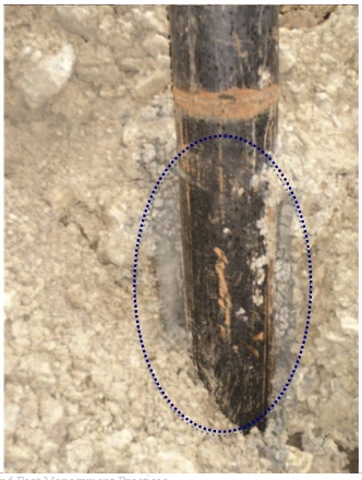
Figure 6-21 shows a close-up of the same drilled well. The photograph shows the bluish-grey bentonite grout that has filled the annular space of the well adjacent to the black drilled well casing and which has adhered to the sand and gravel overburden.
Grout Placement - Pouring Without Tremie Pipe
A tremie pipe is not required when filling the annular space of:
- a new dug well,
- the upper 2.5 m (8.2ft) of a new bored well with approved concrete casing, or
- a new well pit.
The Wells Regulation - The grout (sealant) must provide appropriate structural strength to support the weight of persons and vehicles that may move over the annular space of a dug well or well pit.
Reminder: Care is needed when filling the annular space around a large diameter casing that is thin-walled (e.g., fiberglass or corrugated steel) to reduce the risk of distorting the casing wall or casing joints. Care is also needed when pouring suitable sealant to ensure that bridging will not occur.
Grout Placement - Pouring Bentonite Chips And Pellets From Surface
A dry, manufactured bentonite product, such as chips and pellets, can be placed into the hole’s annular space by a gravity method (i.e., pouring the material from the ground surface) where there is a larger diameter starter (or temporary) casing surrounding a smaller diameter permanent casing. In this case, the starter (or temporary) casing is a pipe that acts as a tremie pipe.
- Tremie Pipe
- A pipe or tube with an inner diameter that is at least three times the diameter of the largest particle of material to pass through it, and that is used to conduct material to the bottom of a hole, including a hole containing standing water.
In this case, the annular space between the starter casing and permanent outer casing must meet the definition of a tremie pipe for this method to be used.
Upon proper placement of the dry bentonite product into the annular space, the starter (or temporary) casing is removed.
If this method of placement of dry bentonite is used, certain precautions should be taken for the reasons discussed below. When pouring dry bentonite from the surface, there is an increased risk of bridging. A high rate of pouring causes the bentonite to clog at an elevation above the bottom of the annular space. In other cases, the bentonite encounters groundwater and hydrates before it settles to the bottom of the annular space. Open gaps, due to bridging, can allow contaminants to travel vertically in the open portion of the well, destabilize the structure of the well and decrease the effectiveness of the plugging materials.
This method may also lead to uneven hydration of dry bentonite in certain situations. As such, improperly hydrated bentonite may not hold the weight of the well column and may cause serious structural problems with the well.
See the best management practice titled “Taking Precautions when Using and Pouring Dry Bentonite Products” in this chapter.
Best Management Practice – Taking Precautions when Using and Pouring Dry Bentonite Products
If sodium bentonite is used and poured in an annular space from the surface using a starter casing or other tremie pipe, the material should be in a pellet or chip form. The material should be screened and placed in accordance with the manufacturer’s specifications.
Precautions when plugging a well with dry bentonite products include the following:
- Installing a considerably larger diameter hole than the casing and the casing has been centered using centralizers.
- Pouring the products at a rate no faster than 3 minutes per 22 kilogram (50 pound) bag.
- Halting the pouring process occasionally and lowering a weighted measuring tape into the well until it reaches the top of the products to confirm that bridging has not occurred.
- Using a tamping device to break any bridges that form.
- Lifting the starter casing as the dry material is added in a manner that keeps the bottom of the tremie pipe immersed in the rising accumulation of dry material, in order to reduce the risk of void spaces between the bentonite and the formation.
- Making sure the bentonite is continually hydrated, where necessary, by periodically adding clean water to the bentonite that has been placed in the well.
- Using a coating on the bentonite that retards swelling for several minutes to allow the bentonite pellets to drop through a shallow water column in the annular space.
- Using slower expanding chips rather than pellets when dropping bentonite through a water column in the annular space.
In situations where there is too much water in the annular space to use a dry bentonite product, a grout mixture and a smaller tremie pipe should be used.
Grout Placement - Displacement Method
The displacement method involves calculating a volume of sealant (grout) material needed to fill the annular space.
Placing Grout Using the Displacement Method
- In many cases, a starter (or temporary) casing is placed into the hole to support the sides of the well. The sealant is typically installed into the drilled hole by a gravity method such as pouring the material from the ground surface. In this case the starter casing acts as a tremie pipe. In other cases, a tremie pipe is lowered into the open hole and the grout is placed into the open hole through a tremie pipe.
Reminder: For further clarification of the definition of Tremie Pipe see Chapter 2: Definitions and Clarifications, Table 2-1 or the “Grout Placement – Pouring Bentonite Chips and Pellets from Surface” section in this chapter.
- A well casing with a plug located on the bottom of the casing is installed into the hole. The grout (sealant) is displaced by the casing and pushed up into the annular space.
Reminder: Plugs should be made of material that is easily drilled through (e.g., wood or cement).
- If the sealant does not fill the entire annular space beside the well casing, then the sealant must be topped up using a tremie pipe to fill the entire annular space to the ground surface.
-
- Where bentonite grout is used, and before further well construction proceeds, allow the bentonite time to achieve gel strength. To achieve full gel strength bentonite takes 8 to 48 hours.
Best Management Practice – Topping Up Settled Bentonite Grout
The bentonite grout should be topped up to the original level before drilling continues if there has been settling or subsidence in the annular space.
- Where cement grout is used, cement grout must be allowed to set according to manufacturer’s specifications, or 12 hours, whichever is longer. If there has been settling or subsidence in the annular space, the cement grout must be topped up to the original level before drilling continues.
- Where bentonite grout is used, and before further well construction proceeds, allow the bentonite time to achieve gel strength. To achieve full gel strength bentonite takes 8 to 48 hours.
- The plug is drilled out or removed from the bottom of the casing.
Reminder: The displacement method using a tremie pipe allows the sealant to be continuously deposited into the hole. The casing with plug can then be installed into the well and meets the requirements of the Wells Regulation. The volume of sealant placed in the hole must be able to rise from the bottom of the annular space to the ground surface.
Figure 6-22: Grout Displacement Method
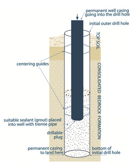
Figure 6-22 shows a cross-sectional diagram of the grout displacement method to place grout (sealant) into a well.
The diagram shows a vertical initial outer drill hole that extends into the subsurface. The subsurface consists of an upper layer of top soil underlain by a consolidated bedrock formation.
A suspended casing has been placed into the hole from above the ground surface to about three quarters of the depth of the hole. The bottom of the casing will eventually rest at the bottom of the initial drill hole. A drillable plug has been placed at the bottom of the casing. Centring guides have been placed on the upper and lower portion of the casing. The centring guides extend from the outside of the casing to the side of the hole. An annular space is located from the outside of the casing to the side of the hole. Suitable sealant (grout) has been placed into the hole with a tremie pipe (not shown) below the casing and around the casing from about half of the depth of the hole to the bottom of the hole.
- Grout measured and placed in hole through a tremie pipe.
- Well casing with bottom drillable plug and centralizers (centering guides) are placed into the well. The bottom of the well casing is placed at the bottom of the inital drill hole in the well.
- Well casing filled with water or pressure applied to hold casing in place until suitable sealant (grout) properly sets.
Reminder: This figure is not to scale, it is for illustrative purposes for this chapter only, and does not necessarily represent full compliance with other requirements found in the Wells Regulation.
Grout Placement - Double Plug Proceduresfootnote 7
The method is more common in the construction of oil and gas wells than water wells. It involves calculating a volume of grout (sealant) material needed to fill the annular space. As this method involves installing the pre-determined batch inside the well casing and pushing it into the annular space from below the well casing, care is needed to determine if the volume of grout (sealant) within the well casing exceeds the volume of the entire annular space.
Reminder: When determining the volume of grout needed, it is important to include an amount of grout that will leave 3 m to 4.6 m (10ft to 15ft) of grout (sealant) in the casing after the annular space has been filled.
Placing Grout Using the Double Plug Method
To place grout using the double plug method:
- A casing with a plug is installed in the hole. The casing is held above the bottom of the well. A pump and pipe are hooked onto the casing above the ground surface.
Reminder: Plugs should be made of material that is easily drilled through (e.g., wood or cement).
- Grout (sealant) is pumped into the casing above the plug. In this case, the casing acts as the tremie pipe.
- A second plug is installed above the grout. The use of a plug helps ensure slurry and water separation, resulting in a proper grout seal at the lower end of the casing.
- Clean water or drilling fluid is then pumped into the casing causing the plugs and grout to move down the casing. As the plugs move down the casing, water or drilling fluid inside the casing is displaced. The process allows the lower plug to fall below the bottom of the casing and the grout moves up and into the annular space.
-
- Where bentonite grout is used, and before further well construction proceeds, the bentonite should be allowed time to achieve gel strength. Bentonite takes 8 to 48 hours to achieve full gel strength.
Best Management Practice – When Bentonite Grout Settles
If there has been settling or subsidence in the annular space, top up the bentonite grout to the original level before drilling continues
- Where cement grout is used, cement grout must be allowed to set according to manufacturer’s specifications, or 12 hours, whichever is longer. If there has been settling or subsidence in the annular space, the cement grout must be topped up to the original level before drilling continues.
- Where bentonite grout is used, and before further well construction proceeds, the bentonite should be allowed time to achieve gel strength. Bentonite takes 8 to 48 hours to achieve full gel strength.
- The plugs are drilled out or removed from the bottom of the casing.
Reminder: Landing collars below the lower plug can be used to reduce the potential for over or under displacement of the grout (sealant). Wire lines attached to the upper plug can also be used to assist in accurately measuring depths when the plugs come together and reduce the risk of damage to the well casing.
Grout Placement - Annular Space For Driven Points
Definition - Construction by a driven point means a method of well construction that uses a solid point or cone that is driven into the ground. This does not include a cutting shoe unless a solid point is installed on an inner rod. This method is not machinery specific.
For example, the type of machinery that can be used to drive the solid point or cone into the ground can include direct push technology, rotary, percussion, pneumatic hammers, sonic, non-powered manual methods, and cone penetration testing equipment.
The Wells Regulation - If a new well is constructed by the use of a driven point, the person constructing the well must ensure that any annular space created is filled to the ground surface using a material and a method approved in writing by the Director. An application must be made to the Director to obtain the written approval.
The request for an approved material and method to seal the annular space of a driven point well must be made and approved prior to constructing the new well. See the following sections in this chapter for details on the written consent process.
Creating And Sealing Annular Spaces Of Driven Point Wells
The driving action during the installation of a driven point well pushes the formation to the sides of the point well and typically does not create a measurable annular space. However, excavations need to be created to connect the driven point well to the horizontal pipe (waterline). The horizontal pipe connects the driven point well to the building’s plumbing. As part of backfilling these excavations, a suitable sealant needs to be placed from the bottom of the trench to within 20 cm (8 inches) of the ground surface. This suitable sealant also needs to be placed from the well casing a minimum distance outward of 20 cm (8 inches) in the excavation. The sealant placed in the horizontal pipe excavation (trench) around the well casing reduces the risk of surface water runoff and other near surface sources of contaminants from migrating down the outside of the well casing and impairing the well water.
Reminder: For further information on backfilling trenches from driven point wells see Chapter 9: Equipment Installation and Figure 6-23 in this chapter.
To ensure that any potential annular space that may be present below the ground surface, or disturbed formation beside the casing, does not act as a pathway for contaminants to enter the water in the well and aquifer, the person constructing a well with the use of a driven point may create an annular space outside of the well casing on purpose. If an annular space is created, the person constructing the well with the use of a driven point must fill the annular space with suitable sealant. If an annular space is created and sealed for a new well constructed with the use of a driven point, the person constructing the well could follow the “Best Management Practice - A Method of Creating and Sealing Annular Space of a Well Constructed with the Use of a Driven Point” in this chapter. However, the Director must provide a written consent to the person constructing the well before an annular space is created and sealed for a new well constructed with the use of a driven-point.
Reminder: For further information on how the Director’s written consent to allow for the creating and sealing of a new well constructed with the use of a driven point see the “Where does the Person Constructing the Well have to go to seek a Written Approval from the Director?” in this chapter.
Best Management Practice – A Method of Creating and Sealing Annular Space of a Well Constructed with the Use of a Driven Point
The person constructing the well with the use of a driven point should do the following:
- A hole should be excavated below the frost line. This hole is part of a trench that will take the horizontal pipe (waterline) from the driven point well to the building’s plumbing.
- Below the excavated area, a well casing with a driven point (or a dynamic cone) that has an outside diameter of at least 11.75 cm (4 5⁄8 inches) into the water producing zone should be driven into the ground. The casing can be driven into the ground with machinery such as direct push technology or by manual methods.
- A driven point well screen and casing that has a diameter of about 6.7 cm (2 5⁄8 inches) should be placed into the 11.75 cm (4 5⁄8 inches) diameter casing. The driven point well should be centered in the 11.75 cm (4 5⁄8 inches) diameter working casing.
-
The 11.75 cm diameter casing is pulled out of the ground leaving the one-time use drive point in the well while doing one of the following:
- The annular space around the screen portion of the drive point is filled with a clean sand or gravel. The top of the sand or gravel should come no closer than 6 m (19.7ft) below ground surface or no closer than 2.5 m (8.2ft) below ground if the only useable aquifer necessitates a shallower well. Recognizing there is a potential for the sand or gravel to bridge due to the small diameter of the well and annular space, it is important to calculate the volume of the annular space around the screen and ensure the same volume of sand or gravel materials is placed into the well. Clean sand or gravel will also need to be poured slowly from the top of the annular space to prevent bridging.
-
The annular space above the sand or gravel is filled by one of the following:
- A tremie pipe is placed in the annular space just above the sand or gravel. The casing portion of the well’s annular space is filled with suitable sealant from the top of the well screen to the floor of the excavation using the tremie pipe and a grout pump. The suitable sealant will typically consist of at least 20% solids of sodium bentonite by weight.
- Sodium bentonite chips or pellets are placed in the annular space. Recognizing there is a potential for the bentonite chips or pellets to bridge due to the small diameter of the well and annular space, it is important to calculate the volume of the annular space and ensure the same volume of plugging materials are added to the well. Sodium bentonite chips and pellets should also be poured slowly from the top of the annular space to prevent bridging. At different intervals, the sodium bentonite chips or pellets will need to be hydrated with clean and potable water to allow the bentonite to expand in the annular space.
- The filling of the well in the excavation should be completed as shown in Chapter 9: Equipment Installation.
Reminder: For Steps 2 through 4, in the Best Management Practice above, different diameters of driven point wells can be used, however, it is important that the initial hole be at least 5 cm (2 inches) larger than the outer diameter of the final well casing to prevent bridging problems in the annular space. This Best Management Practice is shown in Figure 6-23 in this chapter.
Figure 6-23: Suggested Method of Creating and Sealing Annular Space in a Driven Point Well
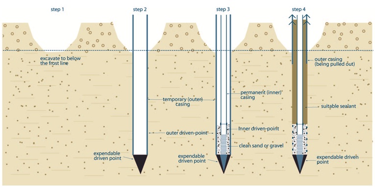
Figure 6-23 shows a cross-sectional diagram of a grout method to creating and sealing an annular space in a driven-point well.
The diagram shows four steps of construction into the subsurface. Near the ground surface, there is a blue dotted horizontal line that represents the frost line.
Step 1 is located on the left side of the diagram. Step 1 shows an excavated hole that extends from the ground surface to below the frost line in the subsurface.
Step 2 shows the same excavated hole as shown in Step 1. Step 2 also shows a vertical temporary (outer) casing that extends from above the ground surface, through the excavated hole and into the subsurface. An expendable driven-point has been placed at the bottom of the temporary (outer) casing.
Step 3 shows the same excavated hole as shown in Step 1. Step 3 also shows the same vertical temporary (outer) casing and expendable driven-point as shown in Step 2. Step 3 shows a permanent (inner) casing within the temporary (outer) casing. The permanent (inner) casing is located from above the ground surface to almost the bottom of the hole created by the temporary (outer) casing and expendable driven-point. A well screen with a driven-point is attached to the bottom of the permanent (inner) casing. The well screen with a driven-point is located within the permanent (outer) casing and expendable driven-point. An annular space has been created between the permanent (inner) casing/well screen and the temporary (outer) casing. Clean sand or gravel has been placed in the annular space from the driven-point to just above the well screen.
Step 4 shows the same excavated hole as shown in Step 1. In addition, Step 4 also shows the same vertical temporary (outer) casing, expendable driven-point, permanent (inner) casing, well screen, inner driven-point and a clean sand or gravel as shown in Step 3. The remaining annular space above the clean sand and gravel has been filled with a suitable sealant. Arrows have been placed on the top of the temporary (outer) casing to represent that the temporary (outer) casing is being pulled out of the ground.
Reminder: Step 4, a T-connection is installed on top of the casing to allow for the horizontal waterline to connect to the well. Additional casing is added on the well from the T-connection to above the ground surface and the trench is backfilled in accordance with the Wells Regulation (see Chapter 9: Equipment Installation).
Lining up the two points helps to centre the inner string. The inner driven point, in some cases, may rest on top of the initial point (e.g., if it is solid).
Reminder: The diagram above is not to scale and is for illustrative purposes for this chapter only, and does not necessarily represent full compliance with other requirements found in the Wells Regulation.
Where Does the Person Constructing the Well Have to Go to Seek a Written Approval From the Director?
If the person constructing the new well is required to seek the written consent of the Director to use an alternate method to fill the annular space of a well constructed by the use of a driven point, the person may contact the Wells Help Desk:
- In writing to Wells Help Desk, Environmental Monitoring and Reporting Branch of the Ministry of the Environment and Climate Change, 125 Resources Road, Toronto, ON M8P 3V6;
- By fax at: 416-235-5960 or
- By e–mail at helpdesk@waterwellontario.ca
For further information, the person constructing the well can contact the Wells Help Desk by telephone at
What Information Is Needed For A Written Approval?
The Ministry assesses each case individually and on its merits. As a minimum, applicant’s contacting the Ministry for a written approval should provide a written request that includes but is not limited to the following information:
- The name of the individual/entity that owns the well
- The location of the well
- The number of wells
- The purpose and use of the well
- The type of casing and well screen that will be used
- The type of sealant material and method being proposed to fill the annular space
- The reason for the proposed sealant material and methods
- If applicable, written certification by the manufacturer/installer/professional engineer that the material and method will properly fill the annular space
- Details on how the person will verify that the placement of the sealant materials in the annular space is uniform and does not bridge
- Details on any flowing well conditions and how the proposed material and method will prevent the vertical movement of groundwater in the annular space and near the well site
- Details on any identified or expected contaminant or mineralized condition and how the proposed material and method will effectively seal the annular space to the ground surface
- Other potential permits or approvals that are being applied for in relation to the construction or use of the well. For example, the need for a Permit To Take Water if the water from the well is being taken at a rate of more than 50,000 litres one any one day for well development purposes.
The person constructing the well may be required to retain a Professional Engineer or Professional Geoscientist who would have to prepare a scientific report showing the appropriate scientific rationale to support the application. The person constructing the well would have to submit the report along with the request for written approval to the Ministry for its consideration.
The Director has reviewed the “Best Management Practice - A Method of Creating and Sealing Annular Space of a Well Constructed with the Use of a Driven Point” and Figure 6-23 in this chapter
In many environments the Director will likely support a material and method for sealing the annular space that is consistent with the “Best Management Practice - A Method of Creating and Sealing Annular Space of a Well Constructed with the Use of a Driven Point” and Figure 6-23 in this chapter. As such, the person constructing the well is encouraged to review the “Best Management Practice - A Method of Creating and Sealing Annular Space of a Well Constructed with the Use of a Driven Point” and Figure 6-23 in this chapter and should indicate on the application, whether and how the standards listed above will be met.
The request for written approval should be submitted to the Ministry along with any and all supporting documents such as a hydrogeological and/or a well design report.
Depending on the case, and as part of the Director’s consideration, the Director may ask other regulators and interested parties to comment on the request.
The person constructing the well and others should be cautioned that obtaining a written consent will not be an automatic process, since the Ministry has to provide for the conservation, protection and management of Ontario’s waters and for their efficient and sustainable use, to promote Ontario’s long-term environmental, social and economic well being.
Based on the information, the Ministry will contact the well owner in writing indicating the Director’s decision.
Tools For Annular Space & Sealing
Table 6-6 provides an example of the types of reference charts and tables that can be used to volumes of holes and casing and determine the approximate amount of suitable sealant needed to fill the annular space.
| Diameter Millimetres |
Diameter Inches |
Volume m3/m |
Volume ft3/ft |
Volume US gal/ft |
Volume Imp gal/ft |
|---|---|---|---|---|---|
| 51 | 2 | 0.002 | 0.022 | 0.161 | 0.134 |
| 64 | 2½ | 0.003 | 0.032 | 0.241 | 0.201 |
| 76 | 3 | 0.005 | 0.054 | 0.402 | 0.335 |
| 89 | 3½ | 0.006 | 0.065 | 0.483 | 0.402 |
| 102 | 4 | 0.008 | 0.086 | 0.643 | 0.536 |
| 114 | 4½ | 0.010 | 0.108 | 0.804 | 0.670 |
| 127 | 5 | 0.013 | 0.140 | 1.046 | 0.871 |
| 140 | 5½ | 0.015 | 0.161 | 1.206 | 1.005 |
| 152 | 6 | 0.018 | 0.194 | 1.448 | 1.206 |
| 165 | 6½ | 0.021 | 0.226 | 1.689 | 1.407 |
| 178 | 7 | 0.025 | 0.269 | 2.011 | 1.676 |
| 191 | 7½ | 0.029 | 0.312 | 2.332 | 1.944 |
| 200 | 7¾ | 0.031 | 0.334 | 2.493 | 2.078 |
| 203 | 8 | 0.032 | 0.344 | 2.574 | 2.145 |
| 216 | 8½ | 0.037 | 0.398 | 2.976 | 2.480 |
| 222 | 8¾ | 0.039 | 0.420 | 3.137 | 2.614 |
| 229 | 9 | 0.041 | 0.441 | 3.297 | 2.748 |
| 241 | 9½ | 0.046 | 0.495 | 3.700 | 3.083 |
| 248 | 9¾ | 0.048 | 0.517 | 3.860 | 3.217 |
| 254 | 10 | 0.051 | 0.549 | 4.102 | 3.418 |
| 279 | 11 | 0.061 | 0.657 | 4.906 | 4.088 |
| 305 | 12 | 0.073 | 0.786 | 5.871 | 4.893 |
| 311 | 12¼ | 0.076 | 0.818 | 6.112 | 5.094 |
| 324 | 12¾ | 0.082 | 0.883 | 6.595 | 5.496 |
| 381 | 15 | 0.114 | 1.227 | 9.169 | 7.641 |
| 438 | 17¼ | 0.151 | 1.625 | 12.144 | 10.120 |
| 445 | 17½ | 0.155 | 1.668 | 12.466 | 10.388 |
| 457 | 18 | 0.164 | 1.765 | 13.190 | 10.992 |
| 508 | 20 | 0.203 | 2.185 | 16.327 | 13.606 |
| 610 | 24 | 0.292 | 3.143 | 23.485 | 19.570 |
| 635 | 25 | 0.317 | 3.412 | 25.495 | 21.246 |
| 762 | 30 | 0.456 | 4.908 | 36.675 | 30.562 |
| 914 | 36 | 0.657 | 7.072 | 52.840 | 44.034 |
Footnotes
- footnote[*] Back to paragraph “Other wells” excludes dug wells, bored wells with concrete casing, jetted wells or wells that are constructed by the use of a driven point.
- footnote[**] Back to paragraph Any annular space that may be created, other than the annular space surrounding a well screen must be sealed to prevent any movement of water, natural gas, contaminants or other material between subsurface formations or between subsurface formations and the ground surface by means of the annular space.
- footnote[1] Back to paragraph David M. Nielsen. Environmental Site Characterization and Ground-Water Monitoring: Second Edition. Taylor and Francis Group, Boca Ratan, FL. 2006. Pages 755 – 769.
- footnote[2] Back to paragraph Halliburton. 2008. Quik Grout Data Sheet. Accessed online.
- footnote[3] Back to paragraph Nielsen, David M. 1991. The Practical Handbook of Environmental Site Characterization and Ground-Water Monitoring, Second Edition. CRC/Taylor & Francis. Boca Raton, FL. Page 665.
- footnote[4] Back to paragraph The term “shear” is explained in the Glossary.
- footnote[5] Back to paragraph Sterrett, Robert J. 2007. Groundwater and Wells-Third Edition. Johnson Screens/a Weatherford Company., New Brighton, MN. Page 453-454.
- footnote[6] Back to paragraph Nielsen, David M. 1991. The Practical Handbook of Environmental Site Characterization and Ground-Water Monitoring, Second Edition. CRC/Taylor & Francis. Boca Raton, FL. Page 765
- footnote[7] Back to paragraph Sterrett, Robert J. 2007. Groundwater and Wells-Third Edition. Johnson Screens/a Weatherford Company., New Brighton, MN. Page 461-462