4. Siting the Well
Chapter Description
Identifying the appropriate location for well construction will dictate the success or failure of any construction activity. Whether the goal is to find a water supply for potable, agricultural or industrial purposes, a comprehensive planning process will assist in identifying the right site for the well. This chapter provides guidance and minimum requirements for siting a well.
Regulatory Requirements - Well Siting
Relevant Sections - The Wells Regulation
- Location of Wells - Section 12(1) - (6)
- Records - Single Well Record - Section 16.3
The Requirements - Plainly Stated
The Wells Regulation requires the person constructing the well to meet the following when siting a well:
Anyone constructing a new well, other than a test hole or dewatering well, must follow all requirements for siting a well in the Wells Regulation.
The site of a new well must meet the minimum horizontal separation distances from contaminant sources that are provided in Table 4-1 and Table 4-2; and
Once a well has been constructed, the well location must be determined and indicated on the well record using a global positioning system (GPS) receiver, according to the instructions on the well record.
| Sewage System | Well with watertight casing to a depth of ≥ 6m (19.7 ft) | Any other well |
|---|---|---|
| earth pit privy | 15m (50ft) | 30m (100ft) |
| privy vault, pail privy | 10m (33ft) | 15m (50ft) |
| greywater system | 10m (33ft) | 15m (50ft) |
| cesspool | 30m (100ft) | 60m (200ft) |
| treatment units (such as a septic tank) | 15m (50ft) | 15m (50ft) |
| distribution pipe in a leaching or filter bed | 15m (50ft) | 30m (100ft) |
| holding tank | 15m (50ft) | 15m (50ft) |
These separation distances apply to any future earth pit privy, privy vault, pail privy, greywater system or cesspool, and a treatment unit, a distribution pipe in a leaching or filter bed, septic tank or holding tanks that has not been constructed but for which a building permit has been issued.
| Drilled Well with watertight casing that extends to a depth of more than 6 m (19.7ft) | Any other well |
|
|---|---|---|
| source of contaminants | 15 m (50ft) | 30 m (100ft) |
Accessibility and Elevation
A person constructing a new well, other than a test hole or dewatering well, as defined in the Wells Regulation, must locate (site) a new well so that it is:
- accessible for cleaning, treatment, repair, testing, inspection and visual examination at all times before, during and after completion of construction of the well; and
- at a higher elevation than the immediate surrounding area.
Relevant Sections - Additional Regulations Or Legislation
Ontario Regulation 332/12 (Building Code) made under the Building Code Act, 1992 - Tables 8.2.1.5, 8.2.1.6A, 8.2.1.6B and 8.2.1.6C
Key Concepts
What to Consider When Siting A Well
Many different factors must be taken into account before choosing where to place or site the well, including the following:
- Natural elements - such as the topography (land surface) of the site, the flow of groundwater, or the location of the aquifer
- Potential sources of contamination - septic systems, chemical storage (see Chapter 2: Definitions & Clarifications, Table 2-2 “contaminant” for further clarification)
- Safety - presence of overhead power lines or buried utilities
Important Information To Know
The list below includes most, but not all of the information and tools that may be needed to help in the planning and siting of the well:
- Size and shape of the property, property elevations – a diagram or simple map – measuring tools as needed
- Location of natural features – trees, topography, etc.
- Location of all nearby surface water sources such as lakes, rivers and creeks
- Location of springs
- Diagram of the property indicating the slope and contours of land to help determine possible direction of the groundwater flow
- Location or planned location of structures and their purposes – barn, storage shed, house, etc.
- Location or planned location of septic or sewage system, underground or on the surface, fuel storage, and the status of existing system(s)
- Location of land application or storage of pesticides, herbicides, and fungicides, inorganic fertilizers, road salt and nutrients
- Distance to and location of any nearby roads, intersections, parking areas
- Location of electrical lines or other potential overhead or underground utilities or hazards
- Location of any previous or existing wells and status – depth, abandoned, by whom, why, when, etc.
- Planned property uses including future grading of the ground surface
- Planned water uses
- Information about geology and formations, aquifer types likely present (i.e. location, rock type and fracturing of any bedrock outcrops on the property or adjacent properties) from well records, oil and gas records or area hydrogeological and geotechnical reports.
- Position of any features, structures and septic systems or other potential contamination sources on adjacent properties
- Position of wells on adjacent properties
- Accessibility issues to ensure the well is accessible for maintenance
Reminder: Well construction may require additional approvals (e.g. Permit to Take Water or environmental compliance approval for a flowing well discharging greater than 50,000 L/day). These approvals should be requested and obtained in advance of a well construction operation.
Reminder: See “Tools for Siting the Well” in this chapter for information and actions involved with site research and assessment.
Assessing and determining potential sources of contaminants is dealt with on a case by case basis. A source of contaminants list may include but is not limited to the following:
- All components of a sewage system under the Building Code Act or Environmental Protection Act,
- A farm animal feed lot,
- An animal manure pile,
- A barn and barnyard used for domestic animals,
- A lagoon,
- An underground or above ground storage tank and lines that are designed to hold and move petroleum hydrocarbons, volatile organic compounds, polychlorinated byphenyls, phenols and other organic chemicals,
- An open or closed hazardous or non hazardous landfill or dump,
- A sewer line,
- A pond,
- Fertilizers, pesticides, herbicides storage and other chemical storage areas,
- Liquid or solid waste transfer facilities,
- Sewage sludge and bio-solid waste spreading and irrigation sites, and
- Winter sand and salt storage facilities.
Reminder: For a more detailed description of “source of contaminant” and “contaminant” see Chapter 2: Definitions & Clarifications, Table 2-2.
How To Assess Contamination Flow
Contaminants, such as bacteria, hydrocarbons and chemicals, can move easily through soil and even more easily through fractured bedrock. Where fractured bedrock occurs at or near the land surface, the potential for contaminants to get into the groundwater is high.
When contaminants move through soil and fractured rock they generally follow the flow of the groundwater. Therefore, it is important to always take the groundwater flow pattern into consideration when siting a well.
Groundwater flow direction can be complex to determine, but the flow often follows the contour or slope of the land and typically discharges into surface water bodies. Figure 4-1 demonstrates potential risks and the flow of contaminants into and with groundwater.
Scenarios where groundwater flow may be complex include the following:
- Multiple shallow and deep aquifers are present and have different groundwater flow directions,
- Preferential flow pathways exist, such as buried hydro or gas lines,
- Many wells pump groundwater from a single aquifer, and
- Wells are present that pump large volumes of groundwater, at a high rate, from an aquifer.
In these and other complex scenarios, the flow of the groundwater is best determined by a Professional Engineer or Professional Geoscientist.
Figure 4-1: Risk of Contamination
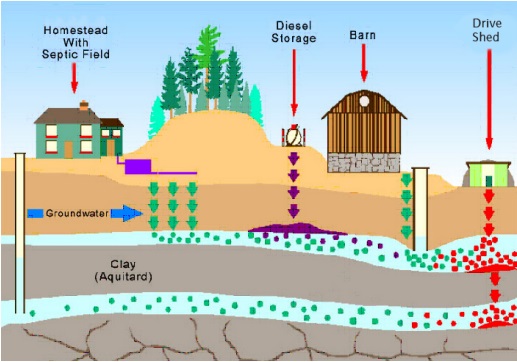
The figure is a cross section illustration of a farm on top of an aquifer system. The farm consists of, from left to right, a homestead with a septic field to the right of the house, followed by a berm with trees, a diesel storage tank, a barn, and a drive shed. There is a well to the left of the homestead, and a well to the right of the barn. The ground consists of, from top to bottom, an unsaturated zone, a vadose zone, an unconfined aquifer, a clay aquitard, a confined aquifer, and fractured bedrock. Groundwater is identified as flowing from left to right across the section.
The well to the left of the homestead is an open pipe well, with the pipe extending from above ground surface and into the confined aquifer. The water level in the well extends upwards into the clay aquitard, indicating that the confined aquifer is pressurized and therefore considered artesian. The well to the right of the barn is also an open pipe well, with the pipe extending from above ground surface and into the top of the unconfined aquifer. The water level in the well is at the same level as the surrounding aquifer .
There are four sources of contaminants illustrated to be entering or already in the aquifer system. The contaminants are identified by arrows in the unsaturated zones, by pools where free product exists, and by dots in the aquifer representing dissolved concentrations. The contaminants include:
- The septic bed to the right of the homestead is discharging effluent downwards through the unsaturated and vadose zones, entering the unconfined aquifer. The contaminants then mix in the aquifer and flow to the right, passing the barn well. They contaminants in the aquifer are identified by green dots.
- The diesel storage tank is discharging light non-aqueous phase liquid (LNAPL) through the unsaturated and vadose zones, and is pooling on top of the unconfined aquifer. Some of the LNAPL is dissolving in the unconfined aquifer and flowing to the right, towards the barn well. The LNAPL pool and dissolved dots are represented in purple.
- Contamination is entering the ground between the barn and the barn well, discharging effluent downwards through the unsaturated and vadose zones, entering the unconfined aquifer. The contaminants then mix in the aquifer and flow to the right, passing the barn well. They contaminants in the aquifer are identified by green dots.
- A dense non-aqueous phase liquid (DNAPL) is discharging from the drive shed, through the unsaturated and vadose zones, and is pooling at the bottom of the unconfined aquifer. The unconfined aquifer has a slight dip to the left (upgradient) and some of the DNAPL is flowing to the left, while dissolved DNAPL is also flowing right in the direction of groundwater flow. Some of the free-product DNAPL is moving down through the clay aquitard at the bottom of the unconfined aquifer and entering the confined aquifer, where it pools at the bottom on the aquifer. The LNAPL pool and dissolved dots are represented in red.
There are also green dots in the confined aquifer, which appear to represent contamination from either the septic bed or contamination from the barn.
Selecting The Site
After the potential sources of contamination and groundwater flow direction have been identified, the well must be sited using the minimum setback distances (see Plainly Stated in this chapter). In addition, the following best management practices are recommended to protect well water quality.
Best Management Practice – Siting the Well Upgradient of Sources of Contamination
Where possible, a well should be located up gradient of potential sources of contamination such as septic systems, storage tanks and others (see Chapter 2: Definitions and Clarifications, Table 2-2 “contaminant”)
Best Management Practice – Exceed Minimum Setback Distance
In some situations it is important to exceed the minimum setback distance specified in the Wells Regulation. For example:
- Any time the natural features of the site indicate that contamination could travel easily and quickly to the water source, and
-
If the well is going to be:
- Situated in a shallow aquifer,
- Set in highly fractured bedrock with thin soil, or
- Located down gradient from a potential contamination source (remember to consider neighbouring properties)
Reminder: The Wells Regulation does not specify a minimum setback distance between a new well and a property line.
Best Management Practice – Recommended Setback Distances from Property Line
Where practical, it is recommended that at least a minimum (or an increased – see the Best Management Practice above) setback distance be applied from the well to all property lines because it is unlikely a well owner can control what happens on adjacent properties. The appropriate setback distance will be dependant on the type of well (e.g. deep drilled or shallow dug) and geologic conditions encountered.
Reminder – See “The Requirements – Plainly Stated” on this chapter for minimum separation distances.
Best Management Practice – Siting the Well in Complex Geology
Where complex geology exists or contamination is likely to be encountered, it is recommended that a Professional Engineer or Professional Geoscientist be retained to site the well.
Best Management Practice – Siting a New Well Near an Existing Water Supply Well
During the planning phase of a new well, all nearby wells should be identified and assessed to determine the impact that the planned well construction could have on the well. If it is determined there is a likelihood that the planned well construction operation may impair the water in a nearby well, drilling should not proceed or proper contingency plans should be put in place to protect the nearby water supply well.
Accessibility And Elevation
The Wells Regulation requires the person constructing a well to site a new well to be accessible for cleaning, treatment, repair, testing, inspection and visual examination at all times before, during and after completion of construction of the well and at a higher elevation than the immediate surrounding area.
The person constructing the well is responsible for ensuring that the new well will be accessible at all times, and taking steps identifying all existing and proposed structures and landscaping that may impact the accessibility. A new well is inaccessible when:
- A building (other than a pump house) or driveway is built over the top of the well
- Buildings or structures are constructed around the well preventing equipment, including a drilling rig or excavator, from accessing the well to rehabilitate, deepen or decommission the well
- The ground surface is landscaped in a manner that prevents equipment, including a drilling rig or excavator, from accessing the well to rehabilitate, deepen or decommission the well
Figure 4-2: Well Located Within A Building
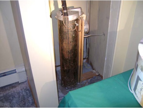
This figure shows a well located within a building. The well is not accessible for significant repairs such as replacing the well casing. New wells in a building, such as a residence, are not allowed under the Wells Regulation.
Clarification of the Term Higher Elevation
For the purposes of constructing a new well on a higher elevation, a new well can be constructed on a sloped property.
However, the Wells Regulation does not allow a new well to be constructed where the ground surface immediately around the well slopes towards the well.
For example, the well cannot be constructed in a ditch.
Where To Record The Well Location
Once a site for the well has been selected, the location of the well must be carefully noted on the well record, including both the Universal Transverse Mercator (UTM) coordinates using a Global Positioning System (GPS) receiver, and an accurate site sketch.
The Wells Regulation requires that a GPS receiver be used to locate the well with accuracy. The UTM coordinates must be recorded as shown in Figure 4-3.
Frequently, well record location data is inaccurate, which limits the usefulness of the record. Providing the most accurate location information is extremely important because it helps to do the following:
- Identify and locate a well in case of a spill,
- Locate a well when maintenance is needed,
- Ensure the correct well is decommissioned in an area with multiple wells,
- Allow for well inspections when a property is being sold, and
- Determine and interpret local groundwater conditions in a given area.
Figure 4-3: Well Record - Recording Well Location
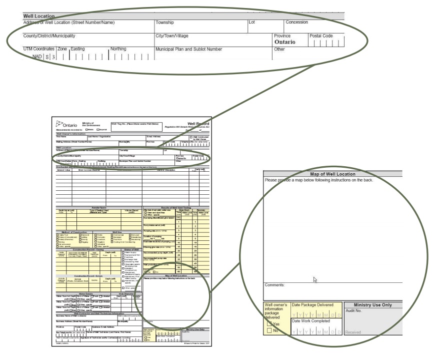
Well Location
- Address of Well Location (Street Number/Name)
- Township
- Concession
- County/District/Municipality
- City/Town/Village
- Province: Ontario
- Postal Code
-
UTM Coordinate: NAD S3
- Zone
- Easting
- Northing
- Municipal Plan and Sublot Number
- Other
Map of Well Location
- Please provide a map bellow following instructions on the back
-
Well owner’s instruction package delivered
- Yes
- No
- Date Package Delivered
- Date Work Completed
Reminder: To allow for the well in the field to be matched with the well record in the Ministry database, it is extremely important that the person constructing the well, fully and accurately completes the well record including all relevant location information. See Chapter 13: Well Records, Documentation, Reporting & Tagging for further guidance on filling out the well record.
Tools For Siting The Well
Site Research & Assessment
| What information is Important? | Why is it important? | What actions should be taken? |
|---|---|---|
| Size and shape of the property. |
|
|
| Position of any features, structures and septic systems or other potential contamination sources on adjacent properties. |
|
|
| Planned property uses as potential sources of contamination. |
|
|
| Distance to and location of any nearby roads, intersections. |
|
|
| Location or planned location of any structures, and their purpose. |
|
|
| Landscaping and final grade of site. |
|
|
| Location or planned location of septic system, underground fuel storage system; and check status of any existing systems. |
|
|
| Information about the geology and the overlying soils. |
|
|
| Topographical features. |
|
|
| Location of previous or existing wells and status. |
|
|
| Position of wells on adjacent properties. |
|
|
| Planned water uses to assess potential water quantity needs. |
|
|
| Location of hydro lines or underground services/utilities. |
|
|
| Accessibility. |
|
|
Footnotes
- footnote[*] Back to paragraph Information provided from Ontario Building Code (Ontario Regulation 332/12 as amended) is current as of January 2014
- footnote[1] Back to paragraph includes a spring used as a source of water for human consumption
- footnote[2] Back to paragraph Agriculture and Agri-Food Canada. 2003. Best Management Practices: Water Wells (BMP12).