5. Constructing, Casing and Covering the Well
Chapter Description
This chapter covers common well construction methods and materials used in Ontario. The minimum requirements for the hole, casing and well screen and advantages and disadvantages of wells constructed using different equipment and materials are also covered. This chapter is structured to parallel the steps involved in the construction of the hole, installation of the casing, creation of the annular space and, where used, installation of the well screen. The filling of sealant in the annular space is covered in Chapter 6: Annular Space & Sealing.
Regulatory Requirements - Hole & Casing
Relevant Sections - The Wells Regualtion
- Log & Field Notes – Section 12.1
- Covering of Well – Section 12.2
- Surface Drainage – Section 12.3
- Well Depth Requirements – Section 12.4
- Well Pits – Subsections 12(7), (7.1), (8) and (9)
- Casing – Section 13
- Deepening of Wells – Section 13.1
- Annular Space – Subsection 14.2(1), Subsection 14.2(2) paragraph 2, Subsection 14.3(1), Subsection 14.4(1), Subsection 14.4(2) paragraph 3, Subsection 14.4(3)
- Double Walled Casing – Section 14.6
- Information – Subsection 16(3)
- Abandonment – Subsection 21(7)
The Requirements - Plainly Stated
Reminder: Figure 5-23 to Figure 5-30 at the end of this chapter show many of the requirements listed in the Plainly Stated section
The Wells Regulation requires the following when a person constructs a water supply well, unless an exemption is provided in this section.
Log Book and Field Notes
The person constructing the well must have an on site, current and detailed:
- log of overburden and bedrock materials encountered when advancing the hole, and
- field notes regarding the construction of the well.
Exemptions - Log Book
The person constructing the well is required to keep up-to-date field notes but is not required to have a log of overburden and bedrock materials if the person is constructing the well by the use of a driven point (e.g., direct push technology, jetting).
Reminder: For further information on log books and field notes requirements and exemptions, see Chapter 13: Well Records, Documentation, Reporting & Tagging.
Covering the Well
Whenever the well is left unattended during construction, the person constructing the well must cover the upper open end of the well securely in order to prevent the entry of surface water and other foreign materials.
Minimum Depth of a New Well
If a new well is being constructed by any method, it must be at least 6 metres (19.7ft) deep unless the only useful aquifer is shallower.
In cases where the only useful aquifer is less than 6 metres (19.7 ft) deep, the well must be at least 3 metres (10 ft) deep.
Reminder: For clarification of the term useful aquifer see Chapter 2: Definitions & Clarifications, Table 2-2.
Well Casing and Well Screen Construction for a New Well
The casing and well screen for a new well must:
- be new materials,
- be clean and free of contamination, and
- not cause contamination of the water with which they are in contact.
Reminder: The requirement for a casing and well screen to be made of new materials prohibits the re-use of a casing or well screen that was previously installed in a finished well (i.e., where its structural stage has been completed). The requirement for a casing to be made of new materials does not apply to starter (working) casing.
Well Casing Sections for a New Well
The casing must be watertight.
Only continuous sections of casing (e.g., no holes or perforations or slots in the well casing) can be used in the construction of a new well.
The casing must meet the minimum standards as outlined in Table 5-1.
Well Casing Seams for a New Well
Any seams in the casing must be permanent and watertight.
Well Casing Joints for a New Well
Joints in casing are not allowed unless they:
- achieve a permanent, watertight bond, such as welded steel joints, and
- are made so that the jointed casing does not impair the quality of water with which it comes in contact.
Concrete Well Casing and Casing Joints for a New Well
If the casing is concrete:
- it must be fully cured and commercially manufactured,
- the concrete sections must be properly aligned so that the joints are flush and the casing is centred, and
- the sections must be joined with a mastic sealing material that remains pliable and waterproof and is approved for potable water use by NSF International.
Reminder: For clarification of the terms “permanent,” “watertight” and “waterproof” see Chapter 2: Definitions & Clarifications, Table 2-2.
Minimum Length of Well Casing Underground for a New Well
Where the useful aquifer is greater than 6 m (19.7ft) below the original ground surface, the casing for a new well must extend at least 6 m (19.7ft) below the original ground surface.
If the only useful aquifer is located between 3 m to 6 m ((10ft to 19.7ft) below the ground surface, the casing for a new well must extend at least 2.5 m (8.2ft) below the level of the original ground surface.
Reminder: For clarification of the terms “useful aquifer”, “permanent”, “watertight” and “waterproof” see Chapter 2: Definitions & Clarifications, Table 2-2.
Surface Drainage (Earth Mounding) around the Well
The person constructing the well must ensure that the slope of the ground surface (surface drainage) is such that water will not collect or pond near the well. Proper surface drainage can be ensured by properly mounding with earth around the well and outward from the well to direct surface drainage away from the well.
Extent of Casing for a New Well in an Overburden Aquifer
Unless exempt, a new well that obtains water from an overburden formation must be cased:
- from the water intake zone,
- to at least 40 cm (16 inches) above the highest point on the ground surface within 3 m (10ft) radially from the outside of the casing after the land is properly mounded for surface drainage as measured on completion of the well’s structural stage.
There is an exemption to this casing requirement which will be discussed in this “Plainly Stated” section (a well constructed by use of a driven point).
Reminder: For clarification of the term “well’s structural stage” see Chapter 2: Definitions & Clarifications, Table 2-2.
Extent of Casing for a New Wells in a Bedrock Aquifer
A new well that obtains water from a bedrock formation, must be cased:
- from the bedrock,
- to at least 40 cm (16 inches) above the highest point on the ground surface within 3 m (10ft) radially from the outside of the casing after the land is properly mounded for surface drainage as measured on completion of the well’s structural stage.
There is an exemption to this casing requirement which will be discussed in this “Plainly Stated” section (a well constructed by use of a driven point).
Reminder: For clarification of the term “well’s structural stage” see Chapter 2: Definitions & Clarifications, Table 2-2.
Sealing Casing in Bedrock for New Drilled Wells
If the aquifer is located in a bedrock zone that is not weathered, the casing of a new drilled well, other than a test hole or dewatering well, must be sealed into the bedrock with suitable sealant to prevent impairment of the quality of the groundwater and the water in the well.
Reminder: For clarification of the term “weathered bedrock” see Chapter 2: Definitions & Clarifications, Table 2-2.
Casing Height Exemption for New Driven Point or Jetted Point Wells
An exemption to the minimum casing height requirement of 40 cm (16 inches) above the ground surface exists if the new well is made by the use of a jetted point or driven point and it has a visible, permanent marker.
In these cases, the casing must:
- extend a sufficient height to permit the attachment of a well tag, and
- be at least as high as the highest point on the ground surface within a 3 m (10ft) radius of the well’s casing for any new well after ground surface is properly mounded with earth to direct surface drainage away from the well as measured on completion of the well’s structural stage.
The permanent marker must also identify the location of the well and be visible at all times of the year.
Reminder: For additional information on casing height and surface drainage see Chapter 7: Completing the Well’s Structure.
Reminder: For clarification of the terms water intake zone and water producing zone see Chapter 2: Definitions and Clarifications, Table 2-2.
Casing Height and Mounding for a New Well in a New Well Pit
If a new drilled well is constructed with a new well pit, the top of the casing of the new drilled well must be at least 40 cm (16 inches) above the floor of the well pit.
The well pit must be cased from the bottom of the well pit to at least 40 cm (16 inches) above the highest point on the ground surface within 3 m (10ft) radially from the outside of the casing as measured upon completion of the well’s structural stage.
The ground surface around the new well pit must be properly mounded to prevent ponding near the well.
New Well Pit Construction for a Well
All new well pits are banned in Ontario, with the exception of:
- wells constructed by diamond drilling equipment that are used in connection with mineral exploration and
- test holes or dewatering wells completed with a properly constructed flush-mounted well pit (vault).
Lightning Rod attachments to Casing for New Wells
A lightning rod is not allowed to be attached, directly or indirectly, to the casing of a new well.
Deepening of an Existing Well
If the well is deepened, all of the casing requirements and exemptions apply, but the existing casing can continue to be used if it appears sound.
A well is not allowed to be constructed by penetrating through the bottom of a bored or dug well by:
- means of drilling,
- the use of a jetted point or
- the use of a driven point.
Information – Encountering Natural Gas
Where a well is constructed and natural gas is encountered, the person constructing the well must immediately notify the well purchaser, the owner of the land on which the well is situated and the Director that the condition exists.
| Casing Type | Wall Thickness | Inside Diameter | Required Standards |
|---|---|---|---|
| Steel |
| > 50.8 mm (2.00 inches) |
|
| Steel |
| ≤ 50.8 mm (2.00 inches) |
|
| Galvanized (bored and dug wells only) | 18 gauge | No minimum diameter | Must be corrugated
|
| Concrete | Nominal thickness of 5.08 cm (2.00 inches) | ≥60.96 cm (24.00 inches) | No standard, but must be fully cured and commercially manufactured |
| Plastic (PVC or ABS) | Minimum thickness of 0.635 cm (0.25 inches) | ≥10.16 cm (4.00 inches) | Must be PVC or ABS and approved for potable water use by ASTM or NSF International |
| Fibreglass | No minimum thickness specified | No minimum diameter | Must be manufactured from virgin resin and virgin fibres and must be approved for potable water use by NSF International |
| High Yield Wells | Minimum thickness dependent on type of material | Minimum diameter size dependent on type of material | Must follow the casing specifications in Table 2 of AWWA A100–06 |
| Double Walled Casings | Minimum thickness dependent on type of material. | Minimum diameter size dependent on type of material | The outer permanent casing in double walled casing construction must be steel pipe that conforms to ASTM A252 or ASTM A500 |
Reminder: See Table 5-7 in this chapter for advantages and disadvantages of different types of well casing.
The Wells Regulation does not allow the use of certain materials as well casing for new well construction. Some examples include the following:
- Casing such as large diameter perforated corrugated pipe (culvert) not approved for potable water use,
- Plastic casing that is not approved for potable water use, and
- Hand lain stone, bricks, wood etc.
Reminder: See the section titled “Improper Casing for New Well Construction” in this chapter for photographs of unapproved types of well casing material.
Relevant Sections - Additional Regulations Or Legislation
Ontario Regulation 213/91 (Construction Projects) as amended made under the Occupational Health and Safety Act
Ontario Regulation 387/04 (Water Taking) as amended made under Ontario Water Resources Act
Relevant Standards
ASTM Standard ASTM A252, 98(2007). “Standard Specification for Welded and Seamless Steel Pipe Piles.” ASTM International, West Conshohocken, PA, 2007, DOI: 10.1520/A0252-98R07, ASTM website.
ASTM Standard A500/A500M, 2007. “Standard Specification for Cold-Formed Welded and Seamless Carbon Steel Structural Tubing in Rounds and Shapes.” ASTM International, West Conshohocken, PA, 2007, DOI: 110.1520/A0500_A0500M-07, ASTM website.
ASTM Standard ASTM D5088, 02(2008) “Standard Practice for Decontamination of Field Equipment Used at Nonradioactive Waste Sites” ASTM International, West Conshohocken, PA, 2007, DOI: 0.1520/D5088-02R08. ASTM website.
ASTM Standard D1173, 2007. “Standard Test Method for Foaming Properties of Surface-Active Agents.” ASTM International, West Conshohocken, PA, 2007, DOI: 10.1520/D1173-07. ASTM website.
ASTM Standard A589/A589M, 2006. “Standard Specification for Seamless and Welded Carbon Steel Water-Well Pipe.” ASTM International, West Conshohocken, PA, 2006, DOI: 10.1520/A0589_A0589M-06, ASTM website.
ASTM Standard F480, 2006b. “Standard Specification for Thermoplastic Well Casing Pipe and Couplings Made in Standard Dimension Ratios (SDR), SCH 40 and SCH 80.” ASTM International, West Conshohocken, PA, 2006, DOI: 10.1520/F0480-06B, ASTM website.
ASTM Standard C990M, 2006 (2009). “Specification for Joints for Concrete Pipe, Manholes, and Precast Box Sections Using Preformed Flexible Joint Sealants.” ASTM International, West Conshohocken, PA, 2009, DOI: 10.1520/C0990-09, ASTM website.
ASTM Standard ASTM C478-07 (2009). “Standard Specification for Precast Reinforced Concrete Manhole Sections.” ASTM International, West Conshohocken, PA, 2009, DOI: 10.1520/C0478-07, ASTM website.
NSF International Standard/American National Standard 61, 2008. “Water Treatment and Distribution Systems - Health Effects.”
NSF International, Ann Arbor, MI 2008. NSF website: Certified fibre-reinforced plastic casing for potable water use (see NSF Products and Service Listings).
American Water Works Association (AWWA). 2003. ANSI/AWWA C 654-03 “Disinfection of Wells.” AWWA, Denver, CO. 2003.
American Water Works Association (AWWA). 2006. ANSI/AWWA A100-06 “Minimum Requirements for Vertical Water Supply Wells.” AWWA, Denver, CO. 2006.
Well Record - Relevant Sections - Hole & Casing
The Wells Regulation - The graphic below shows a sample of the details to be completed on the well record when constructing the hole and installing the casing and well screen in the well.
Figure 5-1: Well Record - Relevant Sections
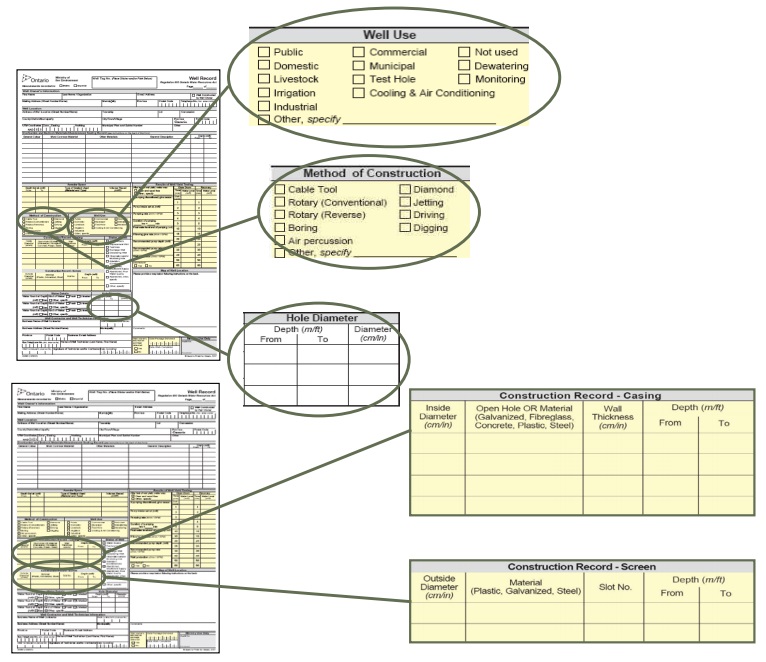
Well Use
- Public
- Domestic
- Livestock
- Irrigation
- Industrial
- Commercial
- Municipal
- Test Hole
- Cooling and Air Conditioning
- Not used
- Dewatering
- Monitoring
- Others; specify
Method of Construction
- Cable Tool
- Rotary (Conventional)
- Rotary (Reverse)
- Boring
- Air percussion
- Diamond
- Jetting
- Driving
- Monitoring
Hole Diameter
- Depth from (m or ft)
- Depth to (m or ft)
- Diameter (cm or in)
Construction Record - Casing
- Inside Diameter (cm or in)
- Open Hole or Material (Galvanized, Fibreglass, Concrete, Plastic, Steel)
- Wall thickness (cm or in)
- Depth from (m or ft)
- Depth to (m or ft)
Construction Record - Screen
- Outside Diameter (cm or in)
- Material (Galvanized, Fibreglass, Concrete, Plastic, Steel)
- Slot No.
- Depth from (m or ft)
- Depth to (m or ft)
Best Management Practice – Reporting Concrete Tile Screens
When constructing a well screen with unsealed concrete tiles, the concrete tiles should be recorded in the “Material” section of the “Construction Record – Screen” box of the well record.
Figure 5-2: Well Record-Relevant Sections(Continued)
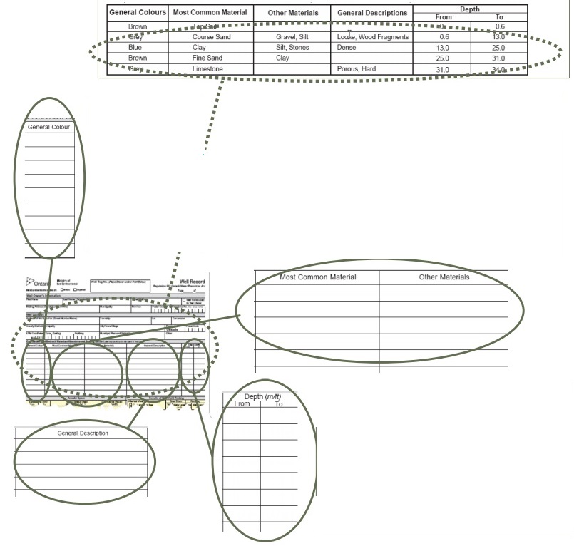
Overburden and Bedrock Materials/Abandonment Sealing Record
The back of the well record provides instructions on how to record the details of this section. The example provided is for construction and is recorded in metric units:
- Coulour
Record the colour of the formation from the list (white, grey, yellow, brown, blue, red, green or black) - Material
Record the material found in the formation (if more than one material exists, record the primary material in the first column and all others in the second column).
Choose materials from the back of the well record (fill, mulch, peat, clay, silt, gravel, stones, boulders, top soil, fine sand, medium sand, coarse sand, limestone, dolomite, shale, sandstone, slate, quartzite, granite and greenstone). - Depth
The depth of each formation encountered must be recorded.
All measurements must be recorded in the units indicated at the top of the well record
All depth measurements are recorded as depth from the ground surface
Reminder: For additional information on filling out the well record see Chapter 13: Well Records, Documentation, Reporting & Tagging.
Key Concepts
Contructing the Hole
Prior to constructing the hole, the person constructing the well should research and assess the site and surrounding area using the tools outlined in Chapter 4: Siting the Well, Table 4-3: Important Information and Actions for Researching and Assessing a Site. Proper research and assessment covers the location of aquifers, nature of geological formations, sources of contaminants, the purpose of the well and site accessibility.
Successful completion of a well depends on the use of equipment and materials that are appropriate for the environmental conditions and geological formations encountered at a site. It is important to consider the characteristics of the drill rig or other well construction equipment including the cutting action and any flushing medium (i.e., drilling of fluid and its circulation path).
Casing
Definition - The Wells Regulation defines casing as “pipe, tubing or other material installed in a well to support its sides, but does not include a well screen.”
Well Screen
Definition - The Wells Regulation defines a well screen as perforated pipe or tubing, unsealed concrete tiles or other material installed in a well to filter out particulate matter, and form the water intake zone.
To prevent water bearing formation collapse into the well and reduce sediment or particles in the well water, a well screen should be installed in all unconsolidated formations, in most semi-consolidated formations and sometimes in bedrock.
Common Types of Well Construction
There are four main types of wells constructed in Ontario:
- Drilled
- Bored/Augered
- Dug (by hand or excavating equipment)
- Driven or jetted
Table 5-2, below provides general characteristics, advantages and disadvantages of the common types of wells.
| Well Type | Suitable Geologic Materials | Advantages | Disadvantages |
|---|---|---|---|
| Drilled Wells [Commonly 15.9 cm (6 inches) in diameter, up to 9,000 m (30,000 ft) deep] |
|
|
|
| Dug Wells [Commonly > 1 m (3 ft) in diameter, up to 10 m (30 ft) deep] |
|
|
|
| Bored Wells [Commonly > 1 m (3 ft) in diameter, up to 30 m (100 ft) deep] |
|
|
|
| Driven-point or Jetted Driven Point wells [Commonly > 5 cm in diameter] |
|
|
|
What to Consider when Constructing a Water Supply Well
Persons constructing water supply wells should research, and be familiar with, the geologic formations in the areas where they construct the wells.
Geologic Formations
Geological materials encountered during well construction could include:
- overburden formations – such as clay, silt, sand, gravel, or stones
- bedrock formations – such as sandstone, limestone, granite, or other bedrock
Reminder: See Chapter 2: Definitions & Clarifications, Table 2-1, for definitions of “overburden” and “bedrock.”
Advancing holes require construction equipment and tools, cutting actions and flushing media appropriate to the geologic formations encountered in each specific hole.
Location Of The Aquifer
Well purchasers, with the assistance of their licensed well technicians or environmental consultants (i.e., Professional Engineers or Professional Geoscientists), can assess and review groundwater reports and well records near the area of the proposed well to understand the subsurface conditions and their implications prior to constructing the wells.
Contaminated Sites
If there is any known or suspected contamination at the site, it is important to consider the following questions:
- What decontamination procedures must be established from hole to hole?
- How are water and/or soil to be contained if contaminated?
- Where will contaminated water and/or soil be stored or disposed of?
- Who will handle the storage and disposal of contaminated water and/or soil?
- What additional health and safety precautions should be taken?
- What is the contingency plan for the rescue of any affected personnel, including identification and location of medical and emergency resources for the site?
Reminder: See Chapter 5: Siting Considerations & Initial Planning for further information on geologic formations, aquifer locations, contaminated sites and environmental site characterization
Accessibility or Space to Work on the Site
It is important that the proper authorization to access and enter the property and to do the work be obtained from the owner of the land and any other party that has an interest in the land (e.g., tenant).
Site access or space to work on the site is an important consideration. Overhead or underground utilities or obstructions may not allow certain equipment (e.g., a drilling rig) to be admitted. Small working space or long distances from roadways may also limit equipment access to the well site. In certain situations, separation distances from sources of contaminants should also be considered (e.g., establishing background groundwater quality).
Reminder: See Chapter 4: Siting the Well for further information on accessibility or space to work at the well site.
Purpose of the Water Supply Well
There are many reasons to construct a well. The purpose of the well may also dictate what type of equipment is required to construct the well. For example, a specialized rotary drilling rig may need to be used to construct a deep large diameter municipal well.
Reasons for constructing a well include the following:
- Domestic water supply
- Livestock watering
- Irrigation
- Industrial
- Commercial
- Municipal or communal water supply
- Public supply
- Cooling, air conditioning or heating (geothermal well)
- Dewatering
- Testing and monitoring
- Recharge (where well is located into groundwater or an aquifer)
Constructing Wells by Different Methods
The following sections provide the key considerations when constructing the hole. Figures 5-23 to 5-30 in the “Diagrams for Common Well Types” section, at the end of this chapter, further illustrate well construction considerations.
Choosing a Construction Method
The construction method:
- should be able to penetrate the geological formation,
- should allow the person constructing the well to get representative samples of geological formation material, to identify the boundaries of permeable zones,
- must allow for the proper recording of formations, including aquifers, encountered during construction,
- must not contaminate the groundwater or the environment,
- unless otherwise exempt, must meet the minimum depth and diameter requirements of the Wells Regulation (see Table 5-5 and Figures 5-23 to 5-30 for minimum diameters), and
- should be able to penetrate the geological formation.
Table 5-3 provides methods, characteristics, and some general advantages and disadvantages of various well construction systems in particular formations.
| System | Characteristics | Advantages | Disadvantages |
|---|---|---|---|
| Conventional Rotary Drilling Water or Mud |
|
|
|
| Conventional Rotary Drilling Air |
|
|
|
| Reverse Circulation Rotary |
|
|
|
| Dual Wall Reverse Circulation Rotary |
|
|
|
| Dual Rotary/ Casing Advancement |
|
|
|
| Down-the-Hole Hammer (Air Percussion Rotary) |
|
|
|
| Cored Hole / Diamond Drilling |
|
|
|
| Cable Tool |
|
|
|
| Bucket Auger |
|
|
|
| Excavator |
|
|
|
| Sonic |
|
|
|
| Jetting |
|
|
|
| Driving |
|
|
|
Table 5-4 provides some general information on the speed of the construction equipment, when used in a particular environment and formation, to construct different types of wells. The table does not provide a ranking.
| Type Of Formation | Cable Tool | Dirtect Rotary (with fluids) | Dirtect Rotary (with air) | Down-the-hole-hammer | Drill-through-casing hammer | Reverse Rotary(with fluids) | Reverse Rotary(dual wall) | Hydraulic Perussion | Jetting | Driven** | Auger | Digging |
|---|---|---|---|---|---|---|---|---|---|---|---|---|
| Dune Sand | 2 | 5 | NR | NR | 6 | 5* | 6 | 5 | 3 or 4 | 5 | ||
| Loose sand and gravel | 2 | 5 | NR | NR | 6 | 5* | 6 | 5 | 5 | 3 | 3 or 4 | 5 |
| Quicksand & flowing sand | 2 | 5 | NR | NR | 6 | 5* | 6 | 5 | 5 | n/a | 1 | *** |
| Loose boulders in alluvial fans or glacial drift | 3 or 2 | 2 or 1 | NR | NR | 5 | 2 or 1 | 4 | 1 | 1 | NR | 3 | 2 |
| Clay and silt | 3 | 5 | NR | NR | 5 | 5 | 5 | 3 | 3 | n/a | 3 | 3 |
| Firm shale | 5 | 5 | NR | NR | 5 | 5 | 5 | 3 | n/a | n/a | n/a | n/a |
| Sticky shale | 3 | 5 | NR | NR | 5 | 3 | 5 | 3 | n/a | n/a | n/a | n/a |
| Brittle shale | 5 | 5 | NR | NR | 5 | 5 | 5 | 3 | n/a | n/a | n/a | n/a |
| Sandstone - poorly cemented | 3 | 4 | NR | NR | n/a | 4 | 5 | 4 | n/a | n/a | n/a | n/a |
| Sandstone - well cemented | 3 | 3 | 5 | NR | n/a | 3 | 5 | 3 | n/a | n/a | n/a | n/a |
| Chert nodules | 5 | 3 | 3 | NR | n/a | 3 | 3 | 5 | n/a | n/a | n/a | n/a |
| Limestone | 5 | 5 | 5 | 6 | n/a | 3 | 3 | 5 | n/a | n/a | n/a | n/a |
| Limestone with chert nodules | 5 | 3 | 5 | 6 | n/a | 3 | 3 | 5 | n/a | n/a | n/a | n/a |
| Limestone with small cracks or fractures | 5 | 3 | 5 | 6 | n/a | 2 | 2 | 5 | n/a | n/a | n/a | n/a |
| Limestone - cavernous | 5 | 3 or 1 | 2 | 5 | n/a | 1 | 5 | 1 | n/a | n/a | n/a | n/a |
| Dolomite | 5 | 5 | 5 | 6 | n/a | 5 | 5 | 5 | n/a | n/a | n/a | n/a |
| Basalts - thin layers in sedimentary rock | 5 | 3 | 5 | 6 | n/a | 3 | 5 | 5 | n/a | n/a | n/a | n/a |
| Basalts - think layers | 3 | 3 | 4 | 5 | n/a | 3 | 4 | 3 | n/a | n/a | n/a | n/a |
| Basalts - highly fractured(lost circulation zones) | 3 | 1 | 3 | 3 | n/a | 1 | 4 | 1 | n/a | n/a | n/a | n/a |
| Metamorphic rocks | 3 | 3 | 5 | 5 | n/a | 3 | 4 | 3 | n/a | n/a | n/a | n/a |
| Granite | 3 | 3 | 5 | 5 | n/a | 3 | 4 | 3 | n/a | n/a | n/a | n/a |
NR - Not Rcommended
n/a - Not Applicable
* Assuming sufficient hydrostatic pressure is available to contain active sand (under high confining pressures).
** Driven means manual and mechanical assisted methods (hand held, electric or pneumatic rotary hammers).
*** Digging in quicksand and flowing sand is not recommended because the hole is not cases as it is advanced and the formation will likely slough.
Reminder: Take all possible precautions to ensure that any contaminated water, soil, vapours or airborne contaminants are contained during all phases of construction.
If groundwater is anticipated to discharge or is discharging from a well during construction at a volume of more than 50,000 litres (11,000 Imp gal) on any one day, a Permit To Take Water under the Ontario Water Resources Act may be required. More information on Permit To Take Water approvals can be found on the Ontario website.
Reminder: The person constructing the well should ensure that the groundwater, drill cuttings and other materials discharging from the well do not cause environmental impacts such as erosion, impairment of surface water courses and off-site flooding. The use of settling pits on the property may be needed to contain the materials and prevent the above problems. A sewage works environmental compliance approval under the Ontario Water Resources Act may be required if the person constructing the well discharges the water, drill cuttings or other material and the discharge capacity exceeds 10,000 litres per day. A guide to explain the sewage works process can be found on the Ontario website.
Flushing Methods
Drilling fluids (flushing media) are an important consideration when choosing a construction method. During certain well construction, drilling fluids will help to do the following:
- Lubricate the drill bit, string and bearings to prevent breakdowns,
- Clean and cool the bit to allow for continued long periods of drilling without having to replace the bit,
- Stabilize the hole by exerting enough pressure to prevent caving,
- Seal the hole wall to reduce fluid loss to the formation, and
- Lift well cuttings from the bottom of the hole to the surface to allow drilling to continue into the formation.
There are three main flushing methods:
- Fluid based [e.g., water; water and bentonite (clay additives); water and polymeric additives; and water, bentonite (clay additives), and polymeric additives]
- Air based (e.g., dry air; air and water mist; air with a film of water containing a foam, and air, foam; and film strengthening materials, such as polymers and bentonite)
- Dry or mechanical based (uses a mechanical action)
For additional information on flushing media (drilling fluids) see the following:
- Table 7: Advantages and Disadvantages of Flushing Methods for Drilling Monitoring Wells, from the Fleming College Continuing Education Course Manual: Monitoring Wells – Construction (for Ontario Well Technicians).
- Practical Handbook of Environmental Site Characterization and Ground-Water Monitoring, Second Edition, by David, M. Nielsen (editor), CRC/Taylor and Francis, Boca Raton, FL. 2005
footnote 5 . - Chapters 16, 17 and 18 of Construction, Dewatering and Groundwater Control – New Methods and Applications, Third Edition
footnote 6 , and - Chapter 8: Drilling Fluids, from Groundwater and Wells, Third Edition. Johnson Screens/ a Weatherford Company. New Brighton, Minnesota.
Location of the Aquifer - Shallow or Deep
A shallow aquifer may make it more feasible to use a backhoe or a boring rig to construct a large diameter well. Aquifers located in bedrock formations require specialized equipment designed to deal with these formations.
The Wells Regulation requires that new wells be a minimum 6 m (19.7ft) in depth unless the only useful aquifer (i.e., a water–bearing formation that is capable of transmitting water in sufficient quantities to serve as a source of a water supply) necessitates a shallower well. In no case is the well allowed to be less than 3.0 m (10ft) deep.
As indicated in Chapter 4: Siting the Well, Table 4-3: Important Information and Actions for Researching and Assessing a Site, well purchasers with the assistance of their licensed well contractors or environmental consultants can assess and review groundwater reports and well records near the area of the proposed well to determine potential groundwater locations.
Reminder: See Chapter 2: Definitions & Clarifications, Table 2-2 for clarification of the term “useful aquifer”.
Size Of The Hole
During construction of a well, an annular space is created when the size of the hole in the ground is larger than the casing and well screen diameter.
A properly filled annular space around a casing will:
- isolate a discrete zone,
- prevent migration of surface water and other foreign materials into the well and aquifers,
- prevent migration of groundwater and/or contaminants between water bearing formations and subsurface formations,
- prevent migration of groundwater and/or contaminants between water bearing formations and the ground surface,
- prevent aquifer depressurization by stopping the upward migration of water along the casing, or
- prevent gas migration.
Where an annular space is created, the space must be large enough to ensure:
- filter pack (clean washed gravel and sand) can be placed beside a well screen, if applicable, and
- suitable sealant (grout) can fill and adhere around the entire outer well casing to prevent surface water, groundwater, natural gas and other foreign materials from migrating along the outside of the well casing.
Figures 5-23 to 5-30 at the end of this chapter show many of the requirements listed in Table 5-5.
Table 5-5 may not apply to situations where an inner casing is surrounded by a larger diameter permanent outer casing. For further information see the double walled casing requirements in the “Plainly Stated” section of Chapter 6: Annular Space & Sealing.
In the case of a water supply well constructed by use of a driven point that creates an annular space, see Chapter 6: Annular Space & Sealing, for annular space sealing considerations.
| Bored Well with Concrete Casing ≥ 6 m Deep | Bored Well with Concrete Casing < 6 m (19.7 ft) Deep | Dug(or Excavated) Well Jetted Well or Wells Constructed by the Use of a Driven Point | Drilled Well or Any Other Well ≥6 m Deep That is not Listed on this Table | Drilled Well or Any Other Well < 6 m (19.7 ft) Deep That is not List on this Table | |
|---|---|---|---|---|---|
| Minimum Depth of Annular Space below Ground Surface at the Diameter Specified in the Next Row | ≥ 6 m (19.7 ft)* | Where no well screen is installed:
If well screen installed:
| No minimum | ≥ 6 m (19.7 ft)* | Where no well screen is installed:
If well screen installed:
|
| Minimum Diameter of Hole Greater than Outer Casing Diameter to Create Annular Space | ≥ 15.2 cm (6 inches) from the ground surface to ≥ 2.5 m (8.2 ft) below the ground surface | ≥ 15.2 cm (6 inches) from the ground surface to ≥ 2.5 m (8.2 ft) below the ground surface | No minimum | ≥ 7.6 cm (3 inches) | ≥ 7.6 cm (3 inches) |
| Minimum Diameter of Hole Greater than Outer Casing Diameter to Create Annular Space | ≥ 7.6 cm (3 inches) from ≥ 2.5 m (8.2 ft) below the ground surface | ≥ 7.6 cm (3 inches) from ≥ 2.5 m (8.2 ft) below the ground surface | No minimum |
|
|
* If any annular space is created below 6 m below the ground surface, it must be sealed as described in Chapter 7: Annular Space & Sealing.
** The requirement does not apply to situations where an inner casing is surrounded by a larger diameter permanent outer casing (see the text before Table 5-5 and exemptions in “Plainly Stated” section of this chapter).
Best Management Practice – Determining the Size of Hole
A person constructing a cased well should create a hole diameter of sufficient size that will allow for:
- filling materials (e.g., filter pack) to be placed in the annular space around and above a well screen (if present), and
- suitable sealant to be placed in the annular space around the casing and adhere to the casing and formation.
In most subsurface conditions a person constructing a well should create a water supply well that is at least 10 cm to 20 cm (4inches to 8 inches) larger than the outer diameter of the casing. The larger size of hole facilitates the proper placement of the suitable sealant and filling materials in the annular space using a tremie pipe.
Care should be taken in determining the size of the hole. The person constructing the hole should ensure that the hole is able to accommodate a casing of sufficient size to allow for the installation of necessary downhole equipment (e.g., pumps).
Reminder: The same minimum hole diameter and annular space requirements and exemptions apply whether the casing is cylindrical or not, See Table 5-5 for additional details. For additional information on annular space and sealing requirements, see Chapter 6: Annular Space & Sealing.
Best Management Practice – Size of the Well’s Annular Space
A person constructing a water supply well should always apply the minimum specifications in Table 5-5, the “Determining the Size of the Hole” BMP above and the Optimum Artificial Filter Pack Characteristics” BMP in the Artificial Filter Packs section of this Chapter, regardless of the length of time that a well is scheduled to be in operation
Contructing Straight and Plumb Holes
No single drilling construction method is best for every type of drilled well or every geologic condition. Each situation may call for a change in the cutting action, flushing media and equipment, as the construction progresses.
A crucial part of constructing a good vertical hole is ensuring that the hole is straight and plumb to minimize problems with placing the casing, placing filling material or suitable sealant in the annular space around the entire well screen and casing and installing pumping equipment.
Causes of a Crooked Hole
Some of the more common reasons that a hole is not straight include the following:
- Excessive pull down on drill string.
- Drilling aggressively through changing hard and soft formations.
- Deflecting off boulders.
- Collaring hole on sloping bedrock surface.
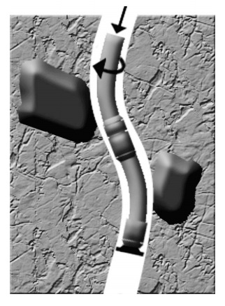
Figure 5-3: A Crooked Hole As A Result Of Drilling Tools Deflecting Off Boulders
Reminder: During construction, a common practice is to use a mirror to reflect sunlight down the hole to permit a visual check on the straightness of the hole. The mirror observation method can be used to check for straightness if a plumb–bob is lowered down the hole. Specifically, a mirror can be used above the water level or when the well is dry to check the following:
- straightness of the hole,
- water levels,
- water entry points in cascading conditions or during pumping,
- condition of the hole or casing,
- occurrence of obstructions in the hole such as boulders, and
- occurrence of leakage of water and unconsolidated material at bedrock – casing interface.
The person constructing the well using rotary drilling equipment should use a mirror and watch the drill string when drilling and tripping in/out to see if the drill string stays in the centre of the casing in the collar area. If the drill string does not stay in the centre of the casing, the hole is not plumb and straight. If using this method, the person constructing the well should ensure that:
- the rig is stable and level, and
- a new or well maintained drill string is used to minimize the degree of deviation within the string.
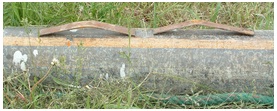
Similarly, the person constructing well using cable tool drilling equipment should look at the relationship of the drill cable to the top of the casing. If the cable is always centred in the casing, then the hole is plumb and straight. If the cable is not centred, then the hole is not plumb and straight.
Best Management Practice – Use Stabilizers and Good Construction Techniques
To help minimize the occurrence of crooked or out of plumb holes, good construction techniques should be used in combination with stabilizers on the drilling tools and inclinometers to measure the angle of the holes.
Figure 5-4: A Drill Bit Stabilizer
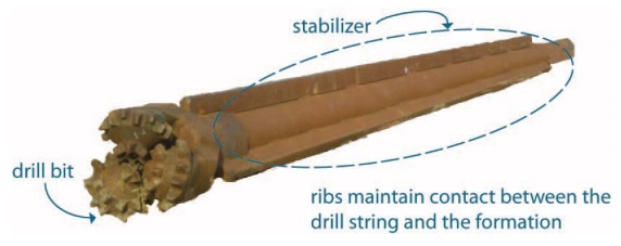
Figure 5-4 shows a drill bit stabilizer. The circled portion shows the stabilizer has three ribs attached to the rod. The use of a stabilizer such as the one shown here, will help keep the hole straight by maintaining wall contact over a long distance.
Creation of Unintended Cavities, Voids and Spaces Outside of the Hole Area
Several factors can contribute to the creation of a cavity, void or space during well construction. These include:
- Cutting action
- Drilling system
- Flushing medium
- Local geology
- Casing accessories such as drive shoes, casing welds, weld rings and couplings
- Drill cuttings being pushed out of the hole
Best Management Practice – Reducing the Risk of Creating Spaces and Voids
To reduce the risk of unintended small voids and spaces that may be difficult to seal, the person constructing the drilled well should:
- Not use a drive shoe with a larger outside diameter than the casing (Table 5-9).
- Minimize the thickness of multiple pass welds (Table 5-9).
- Avoid using a weld ring as it can create a larger annular space (Table 5-9). Instead, a thicker walled casing [e.g., 6.4 mm (0.250 inches) – Table 5-9] should be used to increase the surface area at the ends of the casing to be welded. As an alternative, the person constructing the well should corner cut the casing ends at a 45 degree angle (beveled). The thicker casing provides a stronger welded joint without causing a larger annular space (Table 5-9).
- Minimize the use of band and coupled casing. Welded casing sections should be used instead.
- Use minimum volumes of air or water based flushing media with good drilling practices to minimize hole erosion and to avoid losing circulation.
For a well constructed by the use of a driven point, the person constructing the well should verify that the widest part of the driven point matches the outside diameter of the casing or screen. A wider point could create a very small annular space that is difficult to seal.
If any voids are created on the outside of the casing as a result of the drilling activity, the voids must be filled with suitable sealant or filling material as described in Chapter 6: Annular Space & Sealing.
Covering the Holes
An open hole or excavation is not only a safety hazard for children, farm animals and other living things it is also an open and direct pathway into the aquifer or other subsurface formation. An open well can allow contaminants from spills near the well to enter into the open hole and impair the aquifer.
The Wells Regulation requires that whenever a well under construction is left unattended, including during a minor alteration or the installation of a pump, the person constructing the well must cover the upper open end of the well securely in a manner sufficient to prevent the entry of surface water and other foreign materials into the well.
The person constructing the well must also ensure that the surface drainage is such that water will not collect or pond in the vicinity of the well.
Temporary covers need to prevent surface water or other foreign materials from entering the hole and be secure enough to prevent physical hazards and vandalism. Covering a well may include installing a lockable watertight well cap on top of the well and sealing the cover to the well casing. In cases where there is no casing in the hole, a temporary vertical tube and horizontal cover that is larger than the hole may need to be driven into the ground and around the well.
A person constructing a well must also use covers that meet the requirements of Ontario’s Construction Projects Regulation (Ontario Regulation 213/91
Recording Geological Information
The Wells Regulation requires that the person constructing a new well make a log of the overburden and bedrock materials (geological formations) and keep up-to-date field notes at the well site. This requirement also applies if the person is deepening the well.
A well that is constructed by the use of a driven point are exempt from the requirement to make and keep a log of overburden and bedrock materials but field notes are required to be made, kept up to date, and be available at the well site.
Reminder: See Chapter 13: Well Record, Documentation, Reporting & Tagging for further information on log book and field notes, and an example of a log book entry sheet.
| Major Divisions | Subdivisions | Field Identification | Other Properties |
|---|---|---|---|
| Coarse-Grained Soils/ Sediments | Gravel | Particle size: 6 to 75 mm (¼ to 3 inches) |
|
| Coarse-Grained Soils/ Sediments | Sand | Particle size: < 6 mm (¼ inch), but large enough to be visible to the naked eye |
|
| Fine-Grained Soils / Sediments | Silt |
|
|
| Fine-Grained Soils / Sediments | Clay |
|
|
Reminder: Table 5-6 provides information on one of several grain-size scales used. This is one of several grain-size scales used. A grain-size scale widely used and accepted by geologists, the Udden-Wentworth grain-size scale, is described in Sedimentary Rocks in the Field
The person constructing the well should collect representative samples at measured depths and at intervals that will show the complete geological character of the hole. For example, formation samples could be collected at 1.5 metre (5 feet) intervals and at every change in formation materials. The field notes should document the:
- change in formation materials including the top and bottom of each material/unit encountered,
- observed characteristics of each formation unit,
- depth to groundwater, water quality, natural gas and any other observations (e.g., staining, sheen, odour),
- materials and equipment used at the site and in the well, and
- location information.
Reminder: See Chapter 13: Well Record, Documentation, Reporting & Tagging for further information on log books and field notes and for an example of a log book entry sheet.
Encountering Gas, Contamination and Water Quailty Problems
The Wells Regulation requires that the person constructing the well notify the well purchaser, the owner of the land on which the well is located and the Director if natural gas is encountered.
Definition - Natural gas or other gas is a gas produced from a well that has the potential to create conditions for explosions, poisoning, fire, asphyxiation or other adverse effects at the well site, within the water distribution system connected to the well or within buildings connected to wells. Some problematic gases that have been found in wells in Ontario include methane, hydrogen sulphide, propane, butane, benzene, carbon dioxide and other hydrocarbon based gases.
It is important to be prepared for site-specific conditions, which may include soil and groundwater contamination. Indications of contamination include:
- discolouration or milky colour of the water
- air bubbles in the water
- sheens on the water
- soil staining
- unexpected or foul smell
- hissing or degassing sounds
Best Management Practice – Using Gas Detection Equipment
There is a variety of direct reading instruments used for gas detection including the following:
- combustible gas indicators to measure the risk of fire and explosion, and
- oxygen deficiency meters to assess the level of oxygen in the air.
It is important that the person constructing the well be familiar with:
- gas detection equipment and its limited use and operation, and
- the geology and types of naturally occurring gases that may be encountered in the area.
This information may be available from well records and existing hydrogeological reports.
The person constructing the well should use the gas detection equipment during any well construction in case gas is encountered.
In some cases gas may accumulate in wells after construction. In areas prone to have natural gas, the person constructing the well should use gas detection equipment at least one week after the well has been constructed as a precautionary measure. Also, any person sampling or performing work on a well in areas prone to have natural gas should use gas detection equipment.
Best Management Practice – Encountering Unexpected Contamination or Gas
If unexpected contamination or gas is encountered in the construction (including alteration) of the well, the person constructing the well should stop work immediately to reduce serious dangers to the site crew, well owner and the environment.
To meet the obligation of reporting natural gas to the Director, the person constructing the well should contact the Ministry of the Environment and Climate Change through the Ministry’s Spills Action Centre (SAC) at
Unexpected contamination that is encountered should be reported to the Ministry of the Environment and Climate Change local district office and well owner.
The Ministry can offer assistance and notify other agencies to help reduce serious dangers to the site crew, well owner and the environment.
Best Management Practice – Constructing the Hole in Areas Prone to Explosive Gases
To minimize the risk of gas causing an explosion or fire, a drilling system that uses a water-based drilling fluid and other equipment may be needed to temporarily contain and control the gas during well construction (see the ‘Safety Considerations When Working on Contaminated Sites’ section in this chapter for further information). As each environment is different, the person constructing the well should seek additional advice from a Professional Geoscientist or Professional Engineer on the gas issue before starting or proceeding further with the construction of the well. The Professional Geoscientist or Professional Engineer should create a work plan for the person constructing the well that:
- identifies equipment and procedures to be used to monitor for the presence and migration of hazardous gas;
- identifies measures to be taken to prevent or reduce the likelihood of the migration of hazardous gas,
- identifies measures to be taken to prevent or reduce the likelihood of the migration of hazardous gas,
- identifies a standard of protection that is at least equal to what is required in similar circumstances by “Oil, Gas and Salt Resources of Ontario - Provincial Operating Standards”, version 2.0, dated January 24, 2002 and published by the Ministry of Natural Resources, as amended from time to time, and
- includes a health and safety plan
Reminder: See Chapter 13: Well Records, Documentation, Reporting & Tagging for further information on reporting natural gas or contamination.
Casing
Definition - The Wells Regulation defines casing as pipe, tubing or other material installed in a well to support its sides, but does not include a well screen.
Casing acts to stabilize the hole, prevents unconsolidated overburden materials from entering the well water column, accommodates the pumping, or other equipment, and may be used to seal off or isolate unwanted formations.
The Wells Regulation requires that casings in new wells:
- be made of new materials,
- must not impair the quality of the water,
- must be watertight. Any casing joints and seams must be permanent and also watertight,
- must be clean and free of contamination (including the removal of all visible debris and material prior to the installation of the casing in the hole).
The Wells Regulation - In addition, any casing joints and seams must be permanent and watertight. Any materials used to join casing must not impair the quality of the water.
Best Management Practice – Cleaning Casing
Casing and equipment can be disinfected by following the instructions found in the American Water Well Association Standard C654 titled Disinfection of Wells
Additional information on disinfection of equipment can be found in Chapter 8: Well Disinfection, in the “Initial Steps for New Wells” section.
The Wells Regulation - Where the useful aquifer is greater than 6 m (19.7 ft) below the original ground surface, the casing for a new well must extend at least 6 m (19.7 ft) below the original ground surface.
If the only useful aquifer is located between 3 m to 6 m (10 ft to 19.7ft) below the ground surface, the casing for a new well must extend at least 2.5 m (8.2 ft) below the level of the original ground surface.
Reminder: For clarification of the terms “useful aquifer”, “permanent”, “watertight” and “waterproof” see Chapter 2: Definitions & Clarifications, Table 2-2.
Seating and Sealing Casing into Bedrock
The Wells Regulation - The person constructing a new well must properly seal the casing into the bedrock with suitable sealant to prevent overburden and other foreign materials from migrating under the casing into the well and potentially impairing the quality of the groundwater and water in the well.
Examples of properly sealing the well casing to the bedrock include:
- Seating the bottom of the well casing with a drive shoe into competent bedrock below the top of the overburden/bedrock interface.
- Placing bentonite or a cement product that is suitable for the environment in the annular space at the overburden/bedrock interface.
- A combination of seating the bottom of the well casing and placing a bentonite or cement product in the annular space at the overburden/bedrock interface.
Best Management Practice – Ensuring the Casing is Sealed in the Bedrock
To ensure that the casing is properly sealed into the bedrock, the person constructing the well should use one or both of the following methods:
- Downhole video camera for visual confirmation, or
- Hydraulic packer testing (i.e., sealing the well with an inflatable packer immediately below the well casing and filling the well column above the packer with water. If the water level or pressure in the casing drops then the bottom of the casing is not sealed).
Casing Materials
Choosing the casing material that is best for the specific situation includes consideration of the:
- physical strength to withstand the stress and weight of the formation with depth and seasonal changes such as freezing and thawing,
- resistance to the chemical composition of the groundwater and formation,
- formation characteristics,
- production capacity of the aquifer,
- potential contamination (chemical or biological) in the groundwater,
- purpose for the well, including water uses planned for the well, and
- size of the hole.
The Wells Regulation sets minimum specification standards including wall thicknesses for different types of casing materials in new wells including steel, concrete, fibreglass, and plastic. The casing standards are shown in Table 5-1 in this chapter and the descriptions with advantages and disadvantages are shown in Table 5-7.
| Casing Materials | Characteristics | Advantages | Disadvantages |
|---|---|---|---|
| Steel | Typically used in drilled wells. Reminder: Wall thickness requirements and relevant standards in Table 5-1: Minimum Casing Specifications for New Well Construction |
|
|
| Stainless Steel | Typically used in drilled wells and in highly corrosive environments so that the life of the well is increased. Reminder: Wall thickness requirements and relevant standards in Table 5-1: Minimum Casing Specifications for New Well Construction. |
|
|
| Concrete |
Reminder: Wall thickness requirements in Table 5-1: Minimum Casing Specifications for New Well Construction. |
|
|
| Thermal plastic - PVC |
Reminder: The Wells Regulation does not permit the use of large diameter corrugated plastic pipe that is not approved for potable water use as casing for a new well. Reminder: Wall thickness requirements and relevant standards in Table 5-1: Minimum Casing Specifications for New Well Construction. |
|
|
| ABS (Plastic) |
Reminder: Wall thickness requirements and relevant standards in Table 5-1: Minimum Casing Specifications for New Well Construction. |
|
|
| Fibreglass |
Reminder: Wall thickness requirements in Table 5-1: Minimum Casing Specifications for New Well Construction. |
|
|
| Galvanized Steel |
Reminder: Wall thickness requirements and relevant standards in Table 5-1: Minimum Casing Specifications for New Well Construction. |
|
|
Best Management Practice – Proper Use of Large Diameter Fibreglass Casing
It is the responsibility of the well technician to ensure that larger diameter fibreglass casing typically used in a dug and bored well is appropriate for the geologic environment and well depth. It is important that persons constructing large diameter wells consult with the manufacturers who make fibreglass casing for wells. To reduce the risk of well casing collapse, the fibreglass manufacturer should recommend a casing design for the installation. It is important that the person constructing the well then follow the manufacturer’s recommendations.
Best Management Practice – Proper Use of Concrete Casing
The person constructing the well with concrete casing should consider using concrete tiles designed to ASTM C478–07 titled Standard Specification for Precast Reinforced Concrete Manhole Sections
The structure of the concrete tiles should be sufficient to prevent well collapse.
Concrete tiles should be carefully and evenly backfilled on the outside to ensure the tiles remain plumb.
Joining Casing Lengths
Well Casing Joints for New Wells
The Wells Regulation - Joints in casing are not allowed, unless the joints:
- achieve a permanent, watertight bond, such as welded steel joints, and
- are made so that the jointed casing does not impair the quality of water with which it comes in contact.
Joints for Concrete Casing in New Wells:
The Wells Regulation - If the casing is concrete:
- it must be fully cured and commercially manufactured,
- the concrete sections must be properly aligned so the joints are flush and the casing is centred and plumb, and
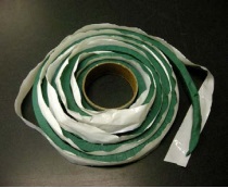
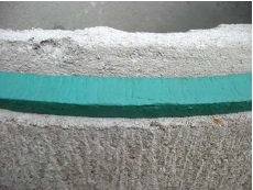
- the sections must be joined with a mastic sealing material (typically butyl rubber material) that remains pliable and waterproof and is approved for potable water use by NSF International Standard - NSF 61.
After the casing length has been attached, additional sand/cement mortar mixes could also be placed on the outside of the casing joint area to help seal the joint.
Best Management Practice – Proper Joining of Concrete Casing
All concrete tile joints should be designed to ASTM C990–06 titled Standard Specification for Joints for Concrete Pipe, Manholes, and Precast Box Sections Using Preformed Flexible Joint Sealants
Reminder: For unsealed joints in concrete tiles used as well screens see the section “Well Screens using Large Diameter Concrete Tiles,” of this chapter.
Table 5-8 provides suggestions and photographs for achieving watertight joints.
Even though Table 5-8 provides suggestions for joining casing, a person constructing a well should determine the type of bond used to seal the joint, or if the casing should even have joints, depending on the well design, environmental conditions and formation.
Reminder: Follow the manufacturer’s specifications regarding how to create permanent watertight joints between casing sections. Table 5-8 provides some suggestions for achieving permanent watertight joints.
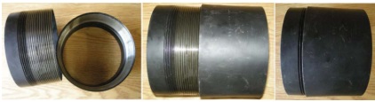
| Casing Type | Method for Achieving Permanent Watertight Joints | Graphic |
|---|---|---|
| Steel Casing | Types of joints:
When welding, use appropriate welding rod for creating the casing joints |
|
| Concrete | Typically joined using bell and spigot method (see fibreglass casing type below). Use mastic sealant (typically butyl rubber material) that is approved for potable water use by the NSF International Standard 61. Concrete tile joints should be designed and sealed to ASTM C990–06 titled Standard Specification for Joints for Concrete Pipe, Manholes, and Precast Box Sections Using Preformed =Flexible Joint Sealants |
|
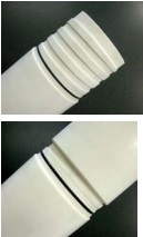
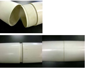
| Plastic | Types of joints:
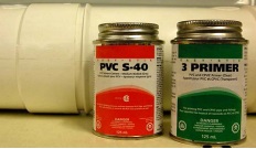
For PVC, use O ring on male thread as per ASTM Standard F480–06be1 “Specification for Thermoplastic Well Casing Pipe and Couplings Made in Standard Dimension Ratios (SDR), Schedule 40 and Schedule 80” For ABS use ABS primer and glue that is approved for potable water use by the NSF International. See best management practice following this table. |
|
| Fibreglass | Joined by male and female joint “bell and spigot”. The casing sections are attached with screws and also sealed with an epoxy. The epoxy must be a material that does not impair the quality of the well water | 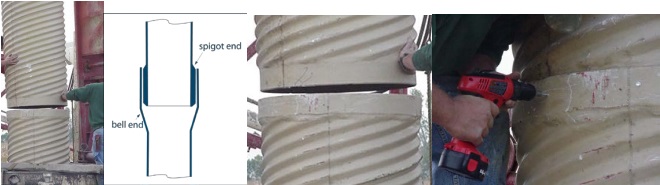 |

Best Management Practice – Joining Sections of PVC Casing
When joining sections of PVC casing, follow ASTM Standard Specification for Thermoplastic Well Casing Pipe and Couplings Made in Standard Dimension Ratios (SDR), Schedule 40 and Schedule 80, ASTM Standard F480, ASTM, West Conshohocken, PA, 2004u.
| Type | Method | Advantages | Disadvantages |
|---|---|---|---|
| Threaded Connections – Acme, Buttress, standard pipe, and square threads |
|
|
|
| Type | Method | Advantages | Disadvantages |
|---|---|---|---|
| Welding Via Application of Heat |
|
|
|
| Threaded Joints |
|
|
|
Improper Casing for New Well Construction
There are some commonly used casing materials that are not allowed for new well construction. Some examples of improper casing include large diameter perforated corrugated pipe (culvert) that is not approved for potable water use; plastic casing that is not approved for potable water use; hand lain stone, bricks or wood. Figures 5-5 to 5-12 provide examples of improper casing used in wells.
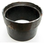
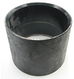
Figure 5-5: Interior of a Well with Plastic Corrugated Pipe
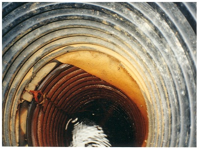
Figure 5-5 shows the interior of a well with plastic corrugated culvert pipes used as casing to support the new well’s sides. Note the two pieces of corrugated pipe separated to allow waterlines and a cloth material into the well.
Figure 5-6 Perforated Hole in Plastic Corrugated Pipe
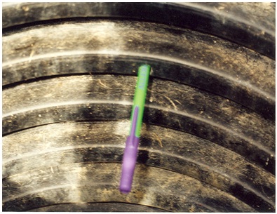
Figure 5-6 shows a pen placed in a perforated hole in the plastic casing. The separated casings and perforated openings allow for foreign materials and contaminants to enter the well. Plastic corrugated pipe is also not approved for potable water use and thus, there is a potential for the piping itself to impair the well water.
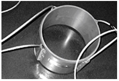
Figure 5-7: Installing Not Approved Galvanized Casing
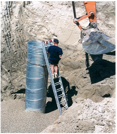
Figure 5-7 shows a person installing galvanized steel casing into a well. However, the spiraling seam in the galvanized casing (typical of a cardboard tube holding a roll of paper towel or holiday paper) has not been welded. The seam is not watertight and allows for foreign materials and contaminants to enter into the well. In addition, the individual is not employing proper safety procedures when working within the excavation of the well.
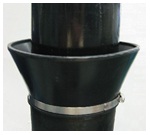
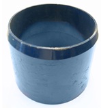
Figure 5-8: Plastic Casing - Type Not Approved
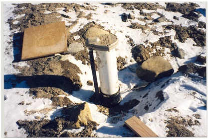
Figure 5-8 shows plastic casing extending out of the top of drilled wells. The plastic pipe is not approved for potable water use and thus, there is a potential for the piping itself to impair well water. If the plastic pipe is approved casing, it will have labeling that identifies the pipe as approved for potable water use. Also, the plastic pipe has been attached improperly to steel casing by a clamping device. The attachment has a space that is not watertight and can allow for surface water and other foreign materials to enter the well and impair the well water.
Figure 5-9: Plastic Casing - Type Not Approved
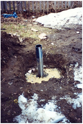
Figure 5-9 shows another photograph similar to Figure 5-8 of plastic casing extending out of the top of drilled wells. The plastic pipe is not approved for potable water use and thus, there is a potential for the piping itself to impair well water. If the plastic pipe is approved casing, it will have labeling that identifies the pipe as approved for potable water use. Also, as in Figure 5-9, the plastic pipe has been attached improperly to steel casing by a clamping device. The attachment has a space that is not watertight and can allow for surface water and other foreign materials to enter the well and impair the well water.
Figure 5-10: Hand Lain Stone Used As Casing - Not Approved
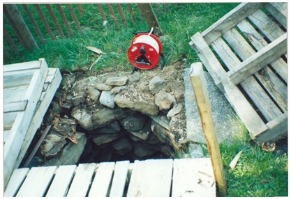
Figure 5-10 shows hand lain stone used as casing. The openings between the stones allow for foreign materials and contaminants to enter into the well. The stone work may also not be structurally adequate to prevent collapse of the well over time. Also, the well cover consists of open wooden pallets that can allow surface water and other foreign materials a route of access into the well leading to the impairment of the well water.
Figure 5-11: Well Within Animal Feedlot - Non-Compliant
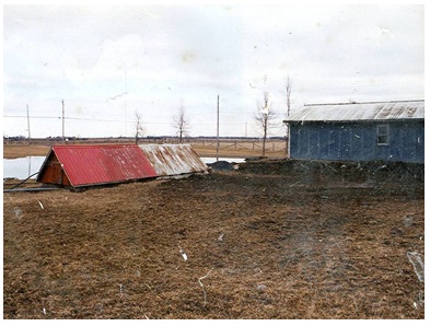
In Figure 5-11 the well is the building with the pitched roof on the left side of the photograph. The rectangular structure is located within an animal feedlot area. The well was used as a source of drinking water for human consumption. See Figure 5-12 for a discussion of the unapproved casing.
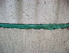
Figure 5-12: Inside the Well Within Animal Feedlot - Unapproved Casing
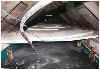
Figure 5-12 shows the interior of the well (building in Figure 5-11). This photograph shows that the well water is a very dark grey colour. Foreign material is floating on the well water. The sides of the well are supported by green painted wooden signs and wood poles. A waterline is extending out of the well water towards the top of the photograph and white styrofoam insulation lies over the well water. The wood used as casing allows for foreign materials and contaminants from the feedlot to enter into the well and impair the well water.
Casing Accessories
Table 5-11 provides details on the most common casing accessories.
| Casing Accessory | Characteristics | Graphics |
|---|---|---|
| Drive Shoes |
|
|
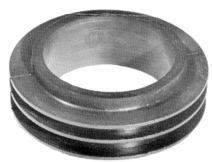
| Weld Rings |
|  |
| Casing Centralizers |
|
|
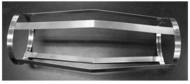
| Breakaway Guide |
|  |
| Shale Trap |
|  |
| K-Packer Device |
|  |
| Examples of casing for drilled wells with different wall thicknesses |
| 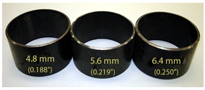 |
Casing Installation Techniques
Casing is installed using one of two techniques:
- Forcing – the forcing techniques include driving, jacking, pushing and rotation.
- Lowering – into an over sized hole.
Safety Note: Extreme care must be used when handling a long string of casing. In deep wells (e.g., 200 m) this is a significant concern for lighter casing materials (e.g., PVC) as well. Devices that require tension alone to hold and secure casing, such as slings and chains, should not be used. Instead, it is advisable to use proper casing elevators.
Centering the Casing
During installation, it is important to ensure casing is centred and vertically plumb in the well.
Proper centering and alignment of the casing in a vertically plumb hole will create an appropriately sized annular space that is consistent around the entire well casing. An appropriately sized annular space allows for even placement of filter pack materials and sealant (grout) around the casing.
Best Management Practice – Centering the Casing
For centering casing in drilled wells, it is important to use and properly attach centralizer devices (see Table 5-11, above) to the outside of the casing. It is important that centralizer devices are made of material that will not impair the quality of the water.
General Guidance for Using the Breakaway Guide:
A breakaway guide (Figure 5-13) may be used to centre the casing in a well constructed by a cable tool drilling rig. The use of a breakaway guide will allow the person constructing the well with a cable tool rig to create a smaller diameter annular space (minimum of 5.1 cm greater than the outer diameter of the casing versus a minimum of 7.6 cm) for a well.
Reminder: For additional information on minimum hole size and annular space requirements see Table 5-5 in this chapter.
When using these breakaway guides, the person constructing the well should:
- Install the working (also called starter or surface) casing as plumb as possible into the hole. The working casing should be used to collar the hole and create a hole that is at least 5.1 cm (2 inches) or greater than the outside diameter of the permanent casing
- Ensure that the drill string is centred in the hole.
- Place the breakaway centralizer guide over the first section of permanent casing so that it is 2 m (6.6 ft) above the bottom of the first permanent casing.
- Install the permanent casing into the well. The breakaway guide is held by cable hooks that rest on the top of the working casing.
- If required, hold the permanent casing at the top with a casing elevator. Drilling the open hole out the bottom of the first permanent casing should continue until the open hole begins to collapse [e.g., 1 to 3 m (3.3 to 6.6 ft)].
- Weld a second length of casing to the first permanent casing.
- Pull out the breakaway centralizer guide using the cables and hooks.
- Fill the annular space with suitable sealant (see Chapter 7: Annular Space & Sealing).
- Continue drilling and advancing casing sections while keeping the sealant (grout) column in the annular space topped up to ground surface during well construction.
- Pull the working casing and top up sealant (grout) to the ground surface when the well is finished.
Figure 5-13 shows a cross-section diagram of this process. The diagram uses the example of a well that is greater than 6 m deep and has a hole diameter (created by the outside diameter of a working casing) slightly greater than the minimum requirement of 5.1 cm larger than the finished permanent casing.
Reminder: All figures and diagrams are for illustrative purposes only and do not necessarily represent full compliance with other requirements found in the Wells Regulation.
Figure 5-13: Example Of The Use Of A Breakaway Centralizer Guide
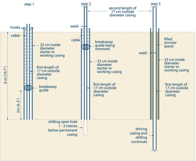
Figure 5-13 shows a cross-sectional diagram of the installation of a breakaway centralizer guide in a drilled well. Figure 5-13 shows three steps.
The first step (Step 1) is shown on the left side of the diagram. Step 1 shows a vertical hole that extends 6 metres (19.7 feet) into the subsurface. A starter casing with an inside diameter of 23 centimeters (9.1 inches), extending from above the ground surface to 6 metres (19.7 feet) below ground has been placed in the hole. Within the starter casing, is a permanent inner casing with an inside diameter of 17 centimetres (6.7 inches). The permanent inner casing extends from above the ground surface to 6 metres (19.7 feet) into the subsurface. A breakaway guide is attached to the outside of the permanent inner casing and extends to the side of the starter casing. The breakaway guide is located about 2 metres (6.5 feet) above the bottom of the permanent inner casing. Hooks are attached to the top of the starter casing. Two cables extend from the hooks to the breakaway guide.
The second step (Step 2) is shown in the centre of the diagram. Step 2 shows a vertical hole extending 7 to 10 metres (23 to 32.8 feet) into the subsurface. A starter casing with an inside diameter of 23 centimeters (9.1 inches), extending from above the ground surface to 6 metres (19.7 feet) below ground has been placed in the hole. Within the starter casing, there is a permanent inner casing with an inside diameter of 17 centimetres (6.7 inches) which extends from above the ground surface to 6 metres (19.7 feet) into the subsurface. The permanent inner casing is comprised of two sections welded together. The joint between the second and first length of permanent inner casing is located above the ground surfaceA breakaway guide is shown attached to the outside of the permanent inner casing and extends to the side of the starter casing. The breakaway guide has been raised from its location in Step 1 to just below the ground surface. Hooks are attached to the top of the starter casing. Two cables extend from the hooks to the breakaway guide. An open hole has been drilled 1 to 3 metres (3.3 to 9.8 metres) below the bottom of the casing.
The third step (Step 3) is shown on the right side of the diagram. Step 3 shows a vertical hole extending greater than 10 metres (32.8 feet) into the subsurface. A starter (or working) casing with an inside diameter of 23 centimetres (9.1 inches) has been placed in the vertical hole. The starter casing extends from above the ground surface to 6 metres (19.7 feet) into the hole in the subsurface. Two sections of permanent inner casing with an inside diameter of 17 centimetres (6.7 inches) are located within the starter casing. The permanent inner casing extends from above the ground surface to the bottom of the hole in the subsurface. The joint between the second and first sections of permanent inner casing is shown below the ground surface. The joint between the two permanent inner casing sections has been welded. The breakaway guide has been removed from the well. The annular space between the permanent inner casing and the starter casing has been filled with a suitable sealant.
- The first weld must be able to pass through casing centralizer guide.
- The casing in step 2 is held in place by the use of an elevator
- The starter, or working, casing must be removed before the structural stage of the well is complete.
- The outer diameter of starter or working casing maskes the hole diameter at least 5.1 cm (2 inches) greater than the permanent casing.
Reminder: The diagram above is not to scale and is for illustrative purposes for this chapter only, and does not necessarily represent full compliance with the requirements found in the Wells Regulation.
Well Screens
To prevent water bearing formation collapse into the well and significantly reduce sediment or particles in the well water, it is important to install a well screen in all unconsolidated formations, in most semi-consolidated formations and sometimes in bedrock.
Definitions - The Wells Regulation defines a well screen as perforated pipe or tubing, unsealed concrete tiles or other material installed in a well to filter out particulate matter and form the water intake zone.
The Wells Regulation requires that well screens for new wells must be made of new materials that are clean and contaminant free. The well screen materials must not impair the quality of the water.
Best Management Practice – Cleaning Well Screens
Well screens, filter packs and equipment should be disinfected by following the instructions found in the most recent version of the American Water Works Association Standard C654 titled Disinfection of Wells.
Well screens that are permitted for use in wells are as follows:
- Commercially manufactured well screens
- Casings that are slotted or perforated to create well screens
- Concrete casings with unsealed joints to create well screens (see “Best Management Practice – Groundwater Entering Large Diameter Wells Cased with Concrete Tiles” on this chapter).
Best Management Practice – Using Clean Pre-Packaged Well Screens
A clean, commercially manufactured pre-packaged well screen that is designed for the formation where the screen will be placed, should be purchased and installed to prevent unconsolidated fines from entering the well and thus creating a hydraulically efficient well.
Reminder: To prevent casing and formation collapse, the person constructing the well should contact the manufacturer of casing before creating a well screen by perforating or slotting the casing.
Well Screen Design Considerations For Drilled Wells
Well Screen Slots, Length and Diameter
Well screen openings (or slots), screen length, and diameter are all selected to allow water to pass through a screen with the least friction, keep out aquifer formation material, and serve as a structural support for the well. Figure 5-14 shows a sample of a telescopic well screen. Telescopic well screens are designed to be pushed out the bottom of the casing. Other well screens are attached to the bottom of the first length of the casing.
Manufactured well screens are made of many materials including steel or plastic. The slots in the well screens may be designed as continuous, louvered, bridged, milled (vertical) and slotted plastic. Table 9.15 on page 398 of Groundwater and Wells: Third Edition
Under certain circumstances and when properly installed, plastic well screens provide wells with adequate structural strength, good hydraulic characteristics, and long life. To prevent the impairment of the well water and aquifer as required by the Wells Regulation, it is important that plastic well screens be approved for potable water use. To ensure sufficient structural strength, the screen manufacturer should be contacted for recommended wall thicknesses when plastic well screens are used.
Manufactured continuous-slot screens have larger open areas compared to the other types of screens. Smaller openings reduce yield, increase drawdown and make well development difficult. Continuous-slot openings are also V-shaped in design. The V-shaped opening allows the open area to widen into the screen. This slot design reduces clogging from elongated or oversized particles.
To ensure optimum use, the well screen entrance velocity needs to be calculated to prevent friction loss and increased rates of encrustation and corrosion.
Best Management Practice - Recommended Maximum Entrance Velocity for Well Screens
It is important that the screen should have a maximum entrance velocity that does not exceed 0.03 metres per second (or 0.1 foot per second) to reduce friction loss and rates of encrustation and corrosion.
The size of the screen slots is determined based on an analysis of the aquifer formation materials. The screen slot size is matched to the grain size distribution of the aquifer formation.
The function of the slot size is important in the well screen. Small openings limit well yield while large openings may not prevent the fine material from entering the well. As a general rule, the slots are sized as shown below in the criteria for selecting a well screen for a drilled well. Then, the formation is developed around the well screen to remove the fines through the screen, leaving the coarser material around the outside of the well screen slots.
Criteria for selecting a well screen for a drilled well include:
- Large percentage of open area
- Generally, where the uniformity coefficient(see definition below) is:
- > 6, the slot size needs to retain no less than 50% of the formation material
- 3 to 6, the slot size needs to retain no less than 60% of the formation material
- < 3, the slot size needs to retain between 70% and 90% of the formation material
- Length of screen
- Planned yield of the well
- Non-clogging slots
- Resistance to corrosion
- Sufficient column and collapse strength
- Ease of well development
- Low potential for encrustation in the formation
- Low head loss through the screen
- Prevention formation collapse during development and when pumping the well
Reminder: Uniformity coefficient is the ratio of the sieve size that retains 40% of the formation material (passes 60% = D60) to the sieve size that retains 90% (passes 10% = effective size)
The Wells Regulation - In cases where a new well with a well screen is constructed by a method other than digging or by the use of a driven or jetted point, the annular space shall be filled with clean, washed gravel or sand:
- from the bottom of the well screen to at least the top of the well screen, and
- not closer than six metres to the ground surface, unless the only useful aquifer available necessitates a shallower well, in which case the top of the gravel or sand shall not be closer than 2.5 metres to the ground surface.
The depth requirement for the top of the sand and gravel layer does not apply if the well is constructed with a casing surrounded by a larger permanent outer casing (sometimes referred to as a double walled casing).
Reminder: The depth requirement for the top of the sand and gravel layer also does not apply to wells constructed by digging or by the use of a driven or jetted point.
Reminder: See Chapter 6: Annular Space & Sealing for further information on requirements for a casing surrounded by a permanent outer casing.
Best Management Practice – Determining Well Screen Slot Size, Length and Target Depth for Wells
Care should be taken to choose the appropriate well screen slot size and length. Care should also be taken to place the well screen at the correct depth. The proper well screen characteristics and depth will allow the well to fulfill its intended purpose.
For example, when formation materials change with depth and the well is naturally developed, the screen slot size may need to be varied over the length of the well screen to match the grain size of the different formation materials.
Best Management Practice – Designing a Well Screen for Drilled Wells to Achieve a Sand-free State
To ensure the well screen chosen will not collapse and will prevent sediment from entering the well water, which could impact the pump operation and water quality, the person constructing the well should:
- only select a well screen that is commercially manufactured,
- ensure that the manufacturer of the well screen being used specializes in overburden grain size analysis, screen slot size and screen design,
- provide manufacturers with well depth and samples of the formation to be screened, or the results of a proper grain sieve analysis,
- determine if an artificial filter pack is necessary to increase well efficiency and to decrease sediment entering the well, and
- make the appropriate selection of manufactured screen material, opening, length and diameter with the assistance of the manufacturer.
Riser Pipes, Leading (Or Lead) Pipes, K-Packers and Plugs for Telescopic Well Screens
A typical manufactured telescopic well screen assembly (shown in Figure 5-14) is installed through the casing of a drilled well. It will consist of the following three following sections:
- A properly sealed plug is located at the bottom of the well screen to prevent formation material from entering through the large opening at the bottom of the well screen. The plug is sealed by either being threaded in or by pressure fitted onto the bottom well screen. The plug should be made of a material (e.g., iron) that can be drilled out of the well for well rehabilitation and abandonment reasons.
- The plug is sealed to a slotted section that has a precisely selected slot size and length.
- A riser pipe is attached above the slotted section of the well screen. The top of the riser pipe is located close to the bottom of the well casing.
A K-packer (shown in Figure 5-14 and Table 5-11) is a commercially manufactured fitting that creates a watertight and sand-tight seal between the riser pipe and well casing. K-packers are commonly made of neoprene rubber, EPDM rubber or rubber and steel. In the past, packers were made of lead (Pb). However, well screen material, including the K-packer, cannot impair the quality of water with which it comes in contact. As lead (Pb) is a contaminant that can leach into the well water, lead (Pb) packers can no longer be used in well construction.
Best Management Practice – Packer Devices for Telescopic Well Screens
Persons installing well screens should use multiple (two or more) K-packers to eliminate the problems created by variations in casing or packer dimensions.
During installation, rubber rings (gaskets) of the K-packer can become damaged by contact with weld slags or beads within casing joints. To reduce damage to the K-packer, a non-toxic (i.e., food grade) lubricant that will not impair groundwater quality should be applied to the neoprene. The person constructing the well should always follow recommendations from the manufacturer regarding the use and installation of K-packers.
A short section of lead or leading pipe [e.g., 1 m (3ft) long] can be added to the bottom of the well screen assembly to create a sump. The term “lead pipe” is not the metal element Pb, but rather a pipe, typically made of stainless steel, that is leading or ahead of the well screen in the hole.
Best Management Practice – Using Bottom Caps or End Plugs
Bottom caps or end plugs should be used on all casing and well screen assemblies. Joints, caps and end plugs must be watertight and may be secured by welds, threads or force fittings. Solvents, glues or adhesives must not be used for casing or screen assemblies where they may impair the quality of the water (see the “Joining Casing Lengths” section of this chapter).
Figure 5-14: Manufactured Telescopic Well Screen Sample for Drilled Wells
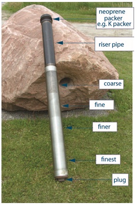
Figure 5-14 shows a sample telescopic screen with multiple slot sizes (from coarse to finest). A typical well screen for domestic use in well construction does not have multiple slot sizes on a small length of screen.
Figure 5-15: An Example of a Telescopic Well Screen Assembly
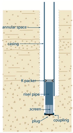
Figure 5-15 shows a cross-sectional diagram of a telescopic well screen assembly. The diagram shows a hole extending vertically into the subsurface. A casing extends from above the ground surface into the hole. An annular space is located between the outside of the casing to the side of the hole. A well screen is shown within the bottom of the casing and extends out of the bottom of the casing into the bottom of the hole in the subsurface. The well screen is made up of a K packer, riser pipe, screen, coupling and plug. The K-packer is located at the top of the well screen and seals the inner casing and to the outside of the well screen. The riser pipe extends from the K-packer to below the bottom of the casing in the subsurface. The screen is located below the riser pipe in the subsurface. The coupling and plug are located below the screen.
Reminder: The diagram above is not to scale and is for illustrative purposes for this chapter only and does not necessarily represent full compliance with other requirements found in the Wells Regulation.
Filter Packs Around Well Screens for Drilled Wells
Filter packs are well sorted gravels or coarse sands that can be:
- developed around the well screen (naturally developed from native granular material),
- selected and placed into the hole surrounding the well screen and developed (artificial filter pack), or
- pre-packed between two manufactured well screens (called pre-packed well screens) and developed.
This packed zone separates the well screen from the natural aquifer material to prevent finer materials from entering the well and increases the effective well diameter. Where possible, the filter pack should extend a sufficient distance above the top of the screen to allow for settling during development.
Reminder: Unless exempt, the person constructing a new well must place filter pack in the annular space around the well screen and casing to the requirements found in the “Plainly Stated” section, Table 6-1A and Table 6-1B of Chapter 6: Annular Space & Sealing.
When selecting a well screen, a slot size should be chosen that will retain approximately 90% of the natural filter pack material after development (see the “Well Screen Slots, Lengths and Diameter,” section of this chapter). The use of a filter pack will generally allow for a coarser well screen slot size. Coarser slot sizes can increase the well efficiency.
Artificial Filter Packs
There are circumstances where an artificial filter pack is preferred over a naturally developed filter pack. Two examples follow:
- Well screens with small screen slots are used with formations having uniform fine grained material. Small slot sizes can create low well efficiency and could reduce the chance of obtaining the desired yield.
- Open hole wells in semi-consolidated bedrock formations can have significant quantities of granular material released off the hole wall. The granular material can enter the water distribution system damaging the pumping equipment and impairing the water quality.
Persons constructing wells can remove formation material around a well screen and replace it with a relatively thin zone of coarse material to increase the well’s efficiency, increase hydraulic diameter and prevent granular material from entering the well. The coarse material that is placed around the well screen is called an artificial filter pack.
As an alternative to placing coarse material around the well screen, the person constructing the well can install a manufactured pre-packed well screen.
The Wells Regulation requires artificial filter pack material or material in a pre-packed well screen to be clean, washed gravel or sand. The gravel or sand must be placed during or after placement of the well screen and casing.
The following best management practices (including Table 5-12) provide artificial filter pack characteristics for obtaining optimum well yield and information on placing artificial filter packs.
Best Management Practice – Optimum Artificial Filter Pack Characteristics
| Characteristics | Advantages |
|---|---|
| Clean and Washed (See “clean” in Chapter 2: Definitions & Clarification; Table 2-1) |
|
| Well rounded and uniform grains |
|
| 90 to 95% quartz grains |
|
| Uniformity coefficient of 2.5 or less |
|
| Filter pack thickness should be no more than 20 cm (8 inches) |
|
| Well screen slot size should retain 90% of filter pack grains |
|
Best Management Practice – Placing Artificial Filter Pack Material
To place an artificial filter pack around a well screen, the hole needs to be properly sized to allow for the well screen and a sufficiently sized annular space around the well screen. The casing and well screen need to be properly centred in the hole to ensure the person constructing the well places a consistent thickness of filter pack material around the well.
To avoid bridging problems, it is important to place artificial filter pack materials in drilled wells:
- using a tremie pipe,
- with a reverse circulation of fluids, or
- with a direct circulation of fluids.
If a tremie pipe is used, the tremie pipe should be raised slowly as the filter material builds up around the well screen. The distance to the top of the filter pack should be carefully monitored using the tremie pipe or a weighted line inserted through the tremie to feel the top of the filter pack.
If a well casing is being raised to expose a well screen and filter pack to the formation (see the section titled: “Pull Back Method”), the person constructing the well should consider the following to prevent finer material from entering the well screen:
- When using a tremie pipe, the artificial filter pack material should be placed in stages as the casing is pulled back to expose the filter pack and well screen to the formation.
- A sufficient depth of filter pack material should be maintained above the well screen slots as the casing is withdrawn.
- The filter pack level should never drop below the bottom of the outer casing.
For more information on filter pack design see Chapter 9 (pages 409 to 419) and Chapter 10 (pages 486 to 491.) of Groundwater and Wells, Third Edition
Well Screen Design Considerations for Large Diameter Wells
Typically, coarse sand or gravel is installed below concrete tiles or other types of casing material to prevent sediment from entering the well water in excavated (dug) and some bored wells. This area of the well is typically called a stone bed and has the following characteristics:
- It is usually about 30 cm (12 inches) to 60 cm (24 inches) thick depending on the environment and well design
- It has to be clean, washed and free of contamination
The following sections provide best management practices for the design of well screens for large diameter wells.
Well Screens Using Large Diameter Fibreglass or Galvanized Material
Best Management Practice – Designing a Well Screen Using Fibreglass or Galvanized Casing in Large Diameter Dug and Bored Wells
In most cases groundwater will enter a large diameter well through the open bottom below the well casing. As a result, slotting of the well casing to create a well screen should not be done.
If it is necessary to obtain groundwater through the sides of the well, then it is important for the person constructing the well to contact the manufacturer of the fibreglass or galvanized casing before creating a well screen by perforating or slotting the casing. Persons constructing wells with these materials should have manufacturer determine and confirm if the type of slotting or perforating will potentially weaken or collapse the casing (and void the warranty) or cause impairment of the well water.
Reminder: It is important to follow the manufacturer’s specifications when backfilling with clean or washed sand and gravel around the outside of fibreglass and galvanized well screens to prevent collapse and warping in particular environments.
Well Screens Using Large Diameter Concrete Tiles
Where the person constructing the well uses concrete tiles as well casing and well screen in bored or dug wells, the well screen begins at the first unsealed joint in the concrete tiles and ends either at the bottom of the unsealed concrete tiles or any gravel or sand installed below the tiles in the excavated hole.
Best Management Practice – Groundwater Entering Large Diameter Wells Cased with Concrete Tiles
Concrete tiles should be:
- designed to ASTM C478–09 titled Standard Specification for Precast Reinforced Concrete Manhole Sections
footnote 22 , - designed in a manner sufficient to prevent well collapse, and
- carefully and evenly backfilled on the outside to ensure the tiles remain plumb.
Groundwater should only enter a large diameter well through the open bottom below the deepest concrete tile. Where groundwater is to enter through the open bottom of the concrete tiles, all concrete tile joints should be designed to ASTM C990–09 titled Standard Specification for Joints for Concrete Pipe, Manholes, and Precast Box Sections Using Preformed Flexible Joint Sealants
Installing Well Screens in Drilling Wells
Properly sized and installed well screens and filter packs reduce the risk of formation collapse and sediment in well water. Failure to install or properly install well screens has been the cause of many problems associated with wells in Ontario such as well plugging, pump and waterline damage, and sediment or granular material in the water supply.
The method of well screen installation is chosen based on practicality and economic feasibility. A particular well design may limit how a well screen can be installed due to:
- aquifer properties,
- methods used to drill the well,
- size and dimensions of the hole, and
- hydraulic conditions,
Some methods of well screen installation include the pull-back, open hole, single string, and bail-down. This section provides general information on all of these methods. The applications, advantages, and disadvantages are summarized in Table 5-13. Outlines of the steps involved in each of these methods are shown following the table.
| Methods | Well Construction Equipment | Advantages | Disadvantages |
|---|---|---|---|
| Pull-back | Best suited for drilling systems that advance the casing as the hole is being constructed. For example:
| Can minimize problems caused by:
Makes it possible to remove and replace the screen without disturbing the casing and sealant (grout) placed around the casing. Allows for the installation of a telescopic screen without having to use a temporary casing. | Heaving formation conditions will create installation problems when using a cable tool or air rotary rig. The person constructing the well may have to employ one of the following options to set the well screen:
Where there is significant side-wall friction, this method requires a great deal of force to pull-back the casing. |
| Open hole (Double string) | Used in rotary drilling rigs in unconsolidated material. | Can minimize problems caused from:
Makes it possible to remove and replace the screen without disturbing the casing and suitable sealant (grout) placed around the casing. Allows for the installation of a telescopic screen without having to use a temporary casing. | Need to use drilling fluid to prevent formation collapse below the well casing. This may make developing more challenging. |
| Open hole (Single string) | Used in narrow drilled wells constructed using rotary drilling rigs in unconsolidated material. | Minimizes the risk of complications due to heaving formations when using mud rotary. Well screen (pipe size) can be installed as part of the casing assembly. | The string offers little column strength and requires support using drilling tools to prevent well screen collapse and crooked wells. For deeper wells in formations that are prone to collapse, an extra outer diameter casing may have to be installed and grouted for a significant portion of the well. Well screen cannot be removed independently of the casing. |
| Bail-down | Used in cable tool rigs and occasionally in rotary drilling rigs in unconsolidated material. Used When:
| Better than the pull back where significant side-wall friction exists. Better than single string methods where high static water level or loose formation materials exist. | Requires special end fittings for the screen. Requires a special nipple that has right and left hand threads and a coupling with right and left hand threads. Requires annular space to be sealed with suitable sealant before installation can start. May require an extra string of casing to rest on top of the screen and provide extra weight. The lower end of this pipe would likely have to be fitted with a coupling or flange to rest squarely on top of a packer without distorting the packer’s shape. |
| Jetting | Used in jetting wells. | Less expensive than other methods. | Only useful for shallow wells obtaining water from sand formations. Possibility of freezing. |
| Driving | Used in Driven wells. | Less expensive than other methods. Not a complicated method. | Only useful for shallow wells obtaining water from sand formations. Possibility of freezing. Possibility of creating small annular space (see Chapter 6: Annular Space & Sealing). |
Pull-Back Methods of Well Screen Installationfootnote 24
The general steps involved in the pull–back method (Figure 5-16) are as follows:
The casing is installed to the full depth of the well. As an alternative, a temporary casing can be installed to the full depth of the well. After the casing is placed in the open hole, any cuttings that settle inside should be carefully cleaned out.
Reminder: Installing the casing to the bottom of the well is particularly important if a delay is anticipated between drilling and well screen installation. The casing will prevent a partial or full collapse of the formation into the hole.
Where a temporary casing has been installed, a permanent smaller diameter well casing is lowered into the temporary casing to the bottom of the hole. A telescopic well screen is pushed inside the permanent casing to the bottom. The bottom of the annular space between the temporary and permanent casings is filled with a filter pack material to a height that extends above the well screen.
Reminder: A weight should be placed on the bottom of the well screen to stop the well screen from migrating upward while the casing is being pulled back prior to proceeding to Step 3. The weight also creates tension to help the person constructing the well determine the exact position of the well screen during the pull-back procedure.
- Where a temporary casing has been installed, the permanent casing is pulled back exposing the well screen and filter pack. Then the temporary well casing is carefully pulled back to expose the well screen and filter pack to the formation.
- In cases where a temporary well casing has not been installed, the casing is pulled back (or lifted) far enough to expose the well screen to the water-bearing formation. The bottom of the casing is raised so that the packer near the top of the well screen remains connected and sealed to the casing and to maximize the screen exposure.
Some methods of lifting the casing include the following:
- jarring and then lifting the casing with the drilling tools, a bumping block or drive clamp,
- lifting the casing using mechanical or hydraulic jacks, and
- using a pulling ring or spider with wedges or slips to grip and lift the casing. Adding clean water to the well during this process may also help.
In situations where no temporary casing has been installed, the well screen will need to be held in place until it is set in the formation. It is important that care be taken to prevent the movement of the well screen during the development and the placement of the suitable sealant in the annular space. See the Tips for Installing Telescopic Well Screens in the next section for further information on preventing the movement of the well screen
Reminder: In situations where a temporary casing has been installed and lifted to expose the well screen and filter pack, the temporary casing must be fully removed from the well after the suitable sealant has been placed into the annular space (See Chapter 6: Annular Space & Sealing).
Tips For The Installation Of A Telescopic Well Screen
Tips for the installation of a telescopic screen are as follows:
- To ensure extra safety when installing the well screen and maximizing exposure of the well screen to the aquifer, a riser pipe (see Figure 5-14 ) with K-packers should be attached to the top of the screen. The riser pipe and K-packers will seal the top of the well screen to the bottom of the casing and prevent the well screen from slipping out of the bottom of the well casing. This will also prevent formation material from entering the well between the well screen and casing.
- When developing the well by surging water into and out of the well screen in loose sand formations, the well screen can easily slip out of the bottom of the casing. A riser pipe with multiple K-packers is especially helpful to hold the well screen in place during development of the well.
- To ensure the well screen is placed in the correct location below the well casing, the depths from the ground surface should be accurately and carefully measured.
Figure 5-16: Drilled Well In Overburden-Casing Pull-Back Method To Expose Well Screen
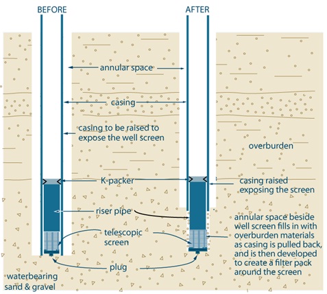
Figure 5-16 shows a cross-sectional diagram of a drilled well in overburden where a casing has been pulled back to expose a well screen. Figure 5-16 shows two steps.
The first step (Before) is shown on the left side of the diagram. The diagram shows a hole is extending vertically into a water-bearing sand and gravel deposit in the subsurface. A casing extends from above the ground surface to the bottom of the hole. An annular space is located between the outside of the casing to the side of the hole. A well screen is shown within the bottom of the casing. The well screen is made up of a K-packer, riser pipe, telescopic screen, coupling and plug. The K-packer is located at the top of the well screen and seals the inner casing and well screen. The riser pipe extends downward from the K-packer to a screen. The screen is located below the riser pipe. The coupling and plug are located below the screen.
The second step (After) is shown on the right side of the diagram. The diagram shows a hole extending vertically into the subsurface. A casing extends from above the ground surface into the subsurface. An annular space is located beside the outside of the casing to the side of the hole. A well screen is shown extending out of the bottom of the casing into the subsurface. The well screen is made up of a K-packer, riser pipe, telescopic screen, coupling and plug. The K-packer is located at the top of the well screen and seals the inner casing and well screen. The riser pipe extends from the K-packer to below the bottom of the casing in the subsurface. The screen is located below the riser pipe in the subsurface. The coupling and plug are located below the screen.
There is text associated with the second step that states “casing raised exposing the screen” and “annular space beside well screen fills in with overburden materials as casing is pulled back, and is then developed to create a filter pack around the screen”.
Reminder: All figures and diagrams are for illustrative purposes only and do not necessarily represent full compliance with other requirements found in the Wells Regulation.
Open Hole/Double String Method of Well Screen Installationfootnote 25
This method generally consists of drilling below the casing while maintaining drilling fluid in the well to hold the well open below the casing. A telescopic well screen is installed into the open space below the well casing.
The general steps for this open hole/double string method are as follows:
- The casing is installed into the well and the annular space is filled with suitable sealant (see Chapter 6: Annular Space & Sealing). The bottom of the casing is slightly below where the top of the well screen will be placed.
- The casing is filled with drilling fluid (e.g., mud). The well is drilled through the bottom of the well casing to make room for the well screen. In some cases where the formation can be held open (e.g., bedrock, till), drilling fluid is not necessary.
- A telescopic well screen is lowered or pushed inside the casing to the bottom of the well. Then the “Tips for the installation of a telescopic screen” on this chapter should be followed.
- If used to hold the hole open, the drilling fluid is removed.
- The well is then developed.
Figure 5-17: Example of an Open Hole, Double String Method of Screen Installation
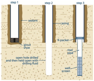
Figure 5-17 shows a cross-sectional diagram of a drilled well in overburden where an open hole, double string method is used to install a well screen. Figure 5-17 shows three steps.
The first step (Step 1) is on the left side of the diagram. The diagram shows a hole extending vertically into the subsurface. In the hole, a casing extends from the ground surface to just above the bottom of the hole. A grout shoe is located at the bottom of the casing. Sealant has been placed in the annular space between the outside of the casing and the side of the hole and also in the bottom of the hole below the bottom of the casing and the grout shoe.
The second step (Step 2) is in the centre of the diagram. The diagram shows a deeper hole extending into the subsurface. In the hole, a casing extends from the ground surface to about half of the distance from above the bottom of the hole. An annular space is shown beside the outside of the casing to the side of the hole. Sealant has been placed in the annular space between the outside of the casing and the side of the hole. The remainder of the hole below the bottom of the casing is held open with a drilling fluid.
The third step (Step 3) is on the right side of the diagram. The diagram shows the hole of Step 2 in which a screen and riser pipe has been installed. A well screen is located within the bottom of the casing and extends out of the bottom of the casing to the bottom of the hole. The well screen is made up of a K packer, riser pipe and well screen. The K-packer is located at the top of the well screen and seals the inner casing and well screen. The riser pipe extends from the K-packer to below the bottom of the casing in the subsurface. The screen is located below the riser pipe in the subsurface.
Reminder: The diagram above is not to scale and is for illustrative purposes for this chapter only, and does not necessarily represent full compliance with the requirements found in the Wells Regulation.
Open-Hole/Single String Method of Well Screen Installationfootnote 26
The general steps for the open hole/single string method (see Figure 5-18) are as follows:
- The well screen is attached to the bottom of the first length of casing to be installed in the well as one assembly (i.e., one string). If the well screen is smaller (in diameter) than the casing, it can be welded or threaded to the casing with a flared weld ring or cone adapter. If the well screen is the same size as the casing, it can be welded or threaded directly to the bottom of the casing.
- Drilling fluid (e.g., mud) is added into the open hole to prevent any collapse of the sides of the well. As an alternative, an outer temporary casing can be installed to the bottom of the well.
- The string is installed in the hole to almost the bottom of the well. Where a temporary outer casing is installed, the inner casing, well screen and filter pack are installed within the outer casing and Steps 4 and 6 do not apply.
- The drilling fluid is thinned to allow the fluid to enter through the slots of the well screen as the string is lowered into the hole. If drilling fluid does not enter into the well screen, the pressure of the drilling fluid could cause the well screen to collapse.
- Because the string is long and slender it offers little column strength and it requires lateral support to prevent well screen collapse and crooked wells. When this string is installed in an open hole without side support, the string should be suspended from the surface using casing elevators without resting the string on the bottom of the hole.
- Once installed, the well screen and casing can be filled with water to displace the drilling fluid.
- For naturally developed wells, the drilling fluid is removed and the fine grained material in the formation is induced to enter the well screen leaving the coarser material on the outside of the well screen. When artificial filter packs are used, the pack material is placed around the well screen and the lower portion of the well casing. The well development process is similar to the natural development of the well. If a temporary outer casing has been installed, the temporary casing is removed to expose the string and filter pack. The well should then be developed.
- Collapse of the subsurface formation around the string provides lateral support and the full weight of the string can be safely released from the drilling rig.
Reminder: In situations where a temporary casing has been installed and lifted to expose the well screen and filter pack, the temporary casing must be fully removed from the well to meet the requirements for placement of suitable sealant in the annular space (See Chapter 6: Annular Space & Sealing).
Tips For Installing Strings
Tips for string installation are as follows:
- Centralizers can help maintain alignment of the casing and well screen string. Centralizers are recommended for well screens that are greater than 6 m (19.7ft) in length.
- If a clay or silt deposit is located beneath the well screen, it is important to prevent the clay or silt from heaving up next to the screen during well development. Two methodologies to prevent clay or silt from entering the well screen are as follows:
- When placed around the well screen, an artificial filter pack can act as a formation stabilizer to hold the clay or silt deposit in place during development (see the section titled “Artificial Filter Pack” in this chapter). The grain size of the filter pack should be chosen as described in Table 5-12: Artificial Filter Pack Characteristics.
- For wells with a large annular space around the well screen, a shale trap or formation packer can be mounted on the bottom of the casing above the well screen. Using this methodology, the formation will collapse around the well screen and below the shale trap or packer. The shale trap or packer will hold the formation in place to prevent heaving of the underlying clay or silt deposit towards the well screen during development
footnote 27 .
- For deeper wells in formations that are prone to collapse, a larger diameter outer casing should be installed and grouted for a significant portion of the well. The lower portion of the well should be drilled through the bottom of the outer casing to the desired depth. It is important that the well casing and open portion of the well be filled with drilling fluid. A smaller diameter casing and well screen string is then installed in the well using the same process as described in the general steps.
- To eliminate the need to run two strings of casing to place artificial filter pack material, a pre-packed screen should be used.
Figure 5-18: Single String Method Using Outer Casing
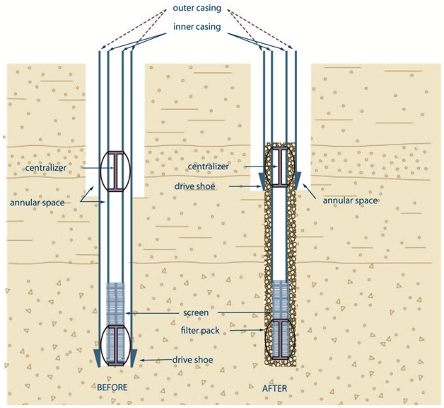
Figure 5-18 shows a cross-sectional diagram of a drilled well in overburden where an open hole, single string method is used to install a well screen. Figure 5-18 shows two steps.
The first step (Before) is on the left side of the diagram. The diagram shows a hole extending vertically into the subsurface. The upper half of the hole is larger than the lower half.
An outer casing extends from above the ground surface to the bottom of the hole. A drive shoe is located on the bottom of the outer casing. An annular space is located beside the outside of the outer casing to the side of the hole.
Within the outer casing is an inner casing with a well screen. This inner casing extends above the ground surface to the bottom of the hole. The well screen is attached to the bottom of the inner casing at the bottom of the hole. There is an annular space between the inner casing and outer casing and between the well screen and the outer casing. A centralizer has been placed at the bottom of the hole between the well screen and outer casing. A second centralizer has been placed in the middle of the hole between the inner casing and the outer casing.
The second step (After) is on the right side of the diagram. The diagram shows a hole extending vertically into the subsurface. The upper half of the hole is larger than the lower half. An outer casing, terminated wih a drive shoe extends from above the ground surface to about half the depth of the hole; below the drive shoe, the hole diameter is more narrow. Within and beyond the outer casing is an inner casing with a well screen. The inner casing, with the screen attached to the bottom, extends above the ground surface to the bottom of the hole. There is an annular space between the inner casing with well screen and the outer casing. There is also an annular space between the inner casing with well screen and the side of the hole below the outer casing. A centralizer has been placed at the bottom of the hole between the well screen and the side of the borehole. A second centralizer has been placed in the middle of the hole between the inner casing and the outer casing. Filter pack has been placed in the annular space around the outside of the inner casing with well screen from the bottom of the well screen to the top of the middle centralizer.
Reminder: The diagram above is not to scale and is for illustrative purposes for this chapter only, and does not necessarily represent full compliance with the requirements found in the Wells Regulation.
Bail-Down Method of Well Screen Installationfootnote 28
The objective of the bail–down method is to remove sediment from below the well screen. The removal of the sediment should allow the well screen to settle into position below the bottom of the casing.
The general steps for the bail-down method (see Figure 5-19) are as follows:
- The casing is installed in the well. The annular space is filled with suitable sealant (see Chapter 6: Annular Space & Sealing). The bottom of the casing is located slightly below where the top of well screen will be placed.
- The bail-down shoe, heavy nipple and float shoe are assembled in the bottom of a telescopic well screen. The well screen will need a threaded bailing pipe (similar to a riser pipe) with K-packers.
- The assembly is lifted from the bailing pipe and lowered into the well. Additional lengths of bailing pipe are added to the assembly as it is lowered into the well until the well screen reaches the bottom of the well.
- A bailer (e.g., a sand pump) is placed inside the bailing pipe. Then the formation material is bailed below the shoe fitting on the well screen. As the formation material is removed, the weight of the well screen and bail pipe causes the well screen to move downward below the bottom of the casing. It is important to carefully measure where the well screen is to be located below the well casing.
- A weighted and tapered plug is dropped through the bailing pipe to plug the heavy nipple on the bail-down shoe. When the plug is in place, the bail pipe is unthreaded from the well screen and removed from the well. The well is then developed.
- In other cases, the well screen is not connected to the bailing pipe. Instead, the bailing pipe is fitted with a flange or coupling large enough to press on the neoprene packer at the top of the well screen to hold it in place. To prevent the well screen from sinking below the casing, care needs to be taken as the movement of the well screen cannot be controlled during the bailing process.
Figure 5-19: Bail-Down Method Of Screen Installation
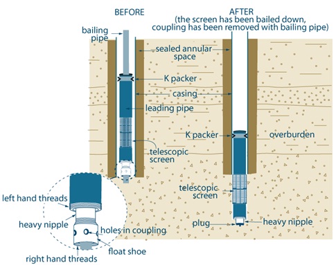
Figure 5-19 shows a cross-sectional diagram of a drilled well in overburden where a bail down method has been used to install a well screen. Figure 5-19 shows two steps.
The first step (Before) is on the left side of the diagram. The diagram shows a hole extending vertically into the subsurface. In the hole, a casing extends from above the ground surface to just above the bottom of the hole. The annular space between the outside of the casing and the side of the hole is sealed. A bailing pipe, leading pipe with k-packer, telescopic screen and a bail-down shoe, heavy nipple and float shoe have been placed within the casing. The bailing pipe extends from above the ground surface to the leading packer and k-packer. The k-packer seals the top of the leading pipe to the inner casing. The telescopic well screen is affixed to the bottom of the leading pipe. The bail-down shoe, heavy nipple and float shoe are affixed to the bottom of the screen. The bail-down shoe, heavy nipple and float shoe extend to the bottom of the hole inside the casing.
An exploded view of the bail-down shoe, heavy nipple and float shoe is shown below and to the left of the first step (Before) diagram. The exploded view shows a cross-sectional diagram of a left handed thread joining the bottom of the well screen to the heavy nipple of the bail-down shoe. A float shoe with holes in its coupling is affixed to the heavy nipple. The bottom of the float shoe has right hand threads.
The second step (After) is on the right side of the diagram. The second step represents the screen bailed down and the coupling and bailing pipe have been removed from the well. The diagram shows a hole extending vertically into the subsurface. In the hole, a casing extends from above the ground surface to the same location as the first step (Before). The annular space between the outside of the casing and the side of the hole is sealed. A leading pipe with k-packer, telescopic screen and a bail-down shoe, heavy nipple and float shoe have been placed within the casing. The k-packer, still located within the casing, seals the top of the leading pipe to the inner casing. Below the bottom of the casing, the telescopic well screen is affixed to the bottom of the leading pipe. The bail-down shoe, heavy nipple and plug are affixed to the bottom of the screen. The bail-down shoe, heavy nipple and plug extend to the bottom of the hole. The screen, heavy nipple and plug extend belong the bottom of the casing into the subsurface.
Reminder: The diagram above is not to scale and is for illustrative purposes for this chapter only, and does not necessarily represent full compliance with the requirements found in the Wells Regulation.
Jetting Methods for Well Screen Installationfootnote 29
Jetting methods are typically used to install well screens to depths of no more than 7.5 m (25ft) below the ground surface in sand formations. There are three jetting methods used to install a well screen:
- Jetting adjacent to the casing and well screen (see Figure 5-20)
- Jetting using a wash pipe (see Figure 5-21)
- Jetting and driving using a drop line and chisel-point bit (see Figure 5-22)
Jetting Adjacent To The Casing And Well Screen
The general steps for this method (see Figure 5-20) are as follows:
- An external pipe is placed adjacent to the casing and well screen string.
- Water is jetted down through the pipe displacing the formation material.
- The jetting action allows the string to sink into the sand formation to the required depth.
- After the jetting pipe has been removed, the well then needs to be developed.
Reminder: See Chapter 6: Annular Space & Sealing for information on the filling of the annular space for a jetted well.
Figure 5-20: Jetting Adjactent to the Casing and Well Screen
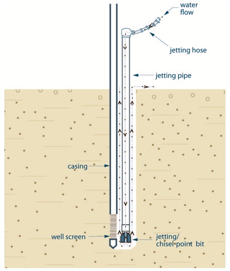
Figure 5-20 shows a cross-sectional diagram of jetting a well screen and casing into the subsurface. The diagram shows a hole extending vertically into the subsurface. On the lefthand side of the hole, a casing extends from above the ground surface into the hole. A well screen is attached to the bottom of the casing. A driven-point is attached to the bottom of the screen. The driven-point extends to the bottom of the hole.
On the right side of the hole, adjacent to the casing is a jetting pipe with a jetting/chisel-point bit. This jetting pipe extends from above the ground surface to the bottom of the hole. The jetting/chisel-point bit is attached to the bottom of the jetting pipe. A jetting hose is attached to the top of the jetting pipe.
There are arrows in the diagram demonstrating the flow of water through the jetting hose down the jetting pipe and discharging out of the jetting/chisel-point bit. There are more arrows in the diagram showing the flow of water and subsurface materials flowing up and around the jetting pipe and discharging out of the hole onto the ground surface.
Reminder: The diagram above is not to scale and is for illustrative purposes for this chapter only, and does not necessarily represent full compliance with the requirements found in the Wells Regulation.
Jetting Using a Wash Pipe For Well Screen Installation
The general steps for this method (see Figure 5-21) are as follows:
- A temporary wash pipe is assembled inside the well screen prior to attachment of the well screen to the bottom of the casing. The bottom of the wash pipe ends near the bottom of the well screen. The wash pipe passes up through the well screen and usually continues upward to about 30 cm to 60 cm (12 to 24 inches) into the casing (see Figure 5-21). The wash pipe may extend to the surface in some shallow wells.
- A coupling is screwed to the lower end of the wash pipe. The coupling rests in a conical seat in the self-closing wash-down fitting, which is equipped with a plastic ball closure.
- A semi-rigid, plastic ring seal is slipped over the upper end of the wash pipe and is pushed into the top of the well screen. The purpose of this upper ring seal is to close the space around the top of the wash pipe and to direct the jetting water down into the wash pipe.
- Water is pumped into the casing, through the top of the wash pipe and jets down through the bottom of the self-closing wash-down fitting.
- In sand formations, the jetting action will allow the string of casing and well screen to sink into the water–bearing formation.
- To achieve depths greater than 7.5m (25ft), it is important to mix drilling fluid additives with the jetting water to suspend cuttings and stabilize the hole in the event that the circulation of the drilling fluid is interrupted.
- During this process, some of the jetting water leaks from around the bottom of the wash pipe and flows out through the well screen openings. This prevents fine sand from passing into the well screen and locking the wash pipe inside the well screen.
- When the well screen has been set at the proper depth, the wash pipe is extracted from the well using a fishing tool.
- After the wash pipe has been removed, the well is then developed.
Figure 5-21: Jetting Small Diameter Well Screens Into Place by Using a Wash Pipe

Figure 5-21 shows a cross-sectional diagram of jetting a small diameter well screen into place using a wash pipe.
The diagram shows a hole extending vertically into the subsurface. The diagram shows the wash pipe and other equipment working to create the well. A casing extends from above the ground surface into the hole. A well screen is attached to the bottom of the casing. A wash pipe extends into the top of the casing and into the well screen. At the bottom of the wash pipe, a self-closing, wash-down fitting ball has been attached to allow water to discharge out of the wash pipe but prevent subsurface materials from entering into the well. A pin to retain the self-closing wash-down fitting ball is affixed to the ball. The bottom of the wash pipe has a coupling that rests in a conical seat. Near the upper portion of the casing in the hole, a ring seal has been placed between the wash pipe and the inside of the casing.
There are arrows in the diagram demonstrating the flow of water from a pump through the wash pipe and discharging out of the wash pipe into the hole. There are more arrows in the diagram showing the flow of water and subsurface materials flowing up and around the casing and discharging out of the hole onto the ground surface.
Reminder: The diagram above is not to scale and is for illustrative purposes for this chapter only, and does not necessarily represent full compliance with the requirements found in the Wells Regulation.
Jetting and Driving Using a Drop Line and Chisel-Point Bit for Well Screen Installation
The general steps for this method (see Figure 5-22) are as follows:
- A chisel-point bit is attached to the bottom of a drop line. The drop line is placed within the well casing.
- Water is jetted through the drop line and the jetting pipe is rotated by hand and adjusted vertically. During jetting, material is washed upward between the inside of the casing and the outside of the drop line. The drop line and bit are also intermittently driven during the process. During the process, the casing will move downward to the required depth.
- The drop line is removed and a telescopic well screen point is inserted. Then, the well screen point is driven out the bottom of the casing. As an alternative, the well screen can be inserted into the bottom of the casing. Then the pull-back method can be used to lift the well casing and expose the well screen to the formation.
Figure 5-22: Screen Installation Using Jetting and Driving Simultaneously
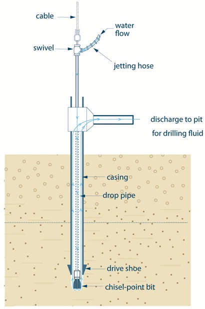
Figure 5-22 shows a cross-sectional diagram of jetting and driving a well screen simultaneously.
The diagram shows the drop pipe, casing and other equipment working to create a well. The diagram shows a hole extending vertically into the subsurface. A casing with a drive shoe extends from above the ground surface into the hole. The drive shoe is attached to the bottom of the casing. A horizontal discharge pipe is attached to the upper portion of the casing above the ground surface.
A jetting pipe extends from above the top of the casing and horizontal discharge pipe into the casing. The bottom of the jetting pipe extends to the bottom of the casing. A chisel-point bit is attached to the bottom of the jetting pipe and is located below the casing.
Above the ground surface, a swivel is attached to the top of the jetting pipe. A jetting hose is attached to the top of the jetting pipe. A vertical cable is shown affixed to the top of the swivel to hold up the jetting hose and jetting pipe above the ground surface.
There are arrows in the diagram demonstrating the flow of water through the jetting hose down the jetting pipe and discharging out of the chisel-point bit. There are more arrows in the diagram demonstrating the flow of water and subsurface materials flowing up and around the jetting pipe within the casing. The arrows in the diagram water demonstrate water and subsurface materials flowing out of the casing into the horizontal discharge pipe and discharging out of the hole onto the ground surface.
Reminder: The diagram above is not to scale and is for illustrative purposes for this chapter only, and does not necessarily represent full compliance with the requirements found in the Wells Regulation.
Driving Methods of Well Screen Installation
Driving methods are typically used to install well screens to depths of no more 7.5 m (25ft) below the ground surface in sand formations. There are 2 common driving methods used to install a well screen:
- driving a telescopic well screen below the casing, and
- driving a casing and well screen string
Driving A Telescopic Well Screen Below The Casing
- A casing is installed within the water bearing formation.
- A telescopic well screen point is inserted with a drive bar. The well screen is driven to expose it below the bottom of the casing while maintaining the seal with the casing.
Driving A Casing And Well Screen String
- Using a drive bar, the casing and well screen string are driven to the water bearing formation.
- As an alternative, hollow stem augers are placed into the ground to the water bearing formation. The casing and well screen string are placed inside the hollow stem augers. The well screen and a portion of the casing are driven with a drive bar below the augers. As the augers are backed out of the hole, the annular space between the augers and the string is filled with an artificial filter pack, where necessary, and a suitable sealant.
Tips When Driving Well Screens
The following tips should be considered when driving a well screen:
- Driving methods requires additional care in sealing the joint between the driven point well screen and casing and between other casing joints.
- Driving methods requires additional care to ensure that the impact of driving does not damage the casing, well screen or joints.
- If a boulder, cobble or other large obstacle is encountered the casing and well screen string may be damaged or deflected. The string may have to be pulled and the hole properly abandoned (See Chapter 14: Abandonment: When to Plug and Seal Wells and Chapter 15: Abandonment: How To Plug and Seal Wells). The string will have to be relocated.
- It is important to use commercially manufactured steel driven points to penetrate the formation.
Reminder: For further information see Figure 5-29 in this chapter, and the “Grout Placement – Annular Space for Driven Points” section in Chapter 6: Annular Space & Sealing.
Diagrams of Common Types of Wells
Reminder: Figures 5-23 to 5-30 show cross sectional illustrations and relevant graphics for various types of wells that have been discussed in this chapter. The illustrations include the minimum size of the hole, the length of casing, the type of well screen and annular space filling materials around the well screen.
Reminder: All figures and diagrams are for illustrative purposes only and do not necessarily represent full compliance with other requirements found in the Wells Regulation (e.g., well covering during construction).
Reminder: For details on the requirements involved in sealing the on the annular space and completing the well, refer to the following chapters in this manual:
- Chapter 6: Annular Space & Sealing
- Chapter 7: Completing the Well’s Structure
Each of the wells shown in Figures 5-23 to 5-30 may encounter conditions that require specialized design or construction. For example:
- flowing artesian conditions
- presence of gas
- pucking and blowing (breathing) conditions where the well and aquifer formation are significantly affected by changes in atmospheric pressure
Reminder: The illustrations and graphics may not depict every circumstance.
Figure 5-23: Drilled Well In Overburden - Well Screens That Are Artificially Packed/Naturally Developed
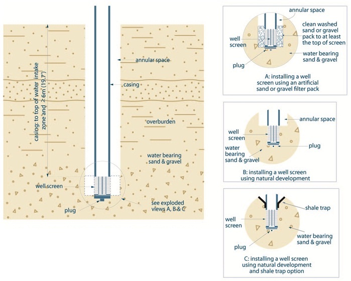
The left side of Figure 5-23 shows a cross-sectional diagram of a drilled well in overburden with a well screen. The bottom of the well is completed with a well screen that is located in a water bearing sand and gravel overburden. A plug is located on the bottom of the well screen. The well screen is attached to the casing. The casing extends vertically from the top of the well screen (the water intake zone) to above the ground surface. There is text adjacent to the casing in the diagram. The text indicates that the casing is required to extend from the ground surface to at least 6 metres (19.7 feet) below the ground surface. There is an annular space around the casing and well screen. It is a requirement that the clean washed sand and gravel can be no closer than 6 metres (19.7 feet) to the ground surface.
There is a circle drawn around the bottom of the well that includes the well screen, the overburden near the well screen and the casing just above the well screen. There is text that states “see exploded views A, B and C” with an arrow pointing from the text to the circle.
The right side of Figure 5-23 shows three exploded views (A, B and C).
Exploded View A shows a cross-sectional diagram of a well screen installed using an artificial sand or gravel pack. The diagram shows the bottom of a well completed with a well screen that is located in the natural water bearing sand and gravel overburden. A plug is located on the bottom of the well screen. The well screen is attached to the bottom of the casing. There is an annular space around the outside of the casing and well screen. The annular space around the outside of the well screen is filled with cleaned wash sand or gravel.
Exploded View B shows a cross-sectional diagram of a well screen installed using natural development. The diagram shows the bottom of a well completed with a well screen that is located in the natural water bearing sand and gravel overburden. A plug is located on the bottom of the well screen. The well screen is attached to the bottom of the casing. There is an annular space around the outside of the casing but not around the screen. The overburden has collapsed around the outside of the well screen. The overburden around the well screen is developed to remove finer subsurface material and allow groundwater to enter the well through the well screen.
Exploded View C shows a cross-sectional diagram of a well screen installed using natural development and a shale trap. The diagram shows the bottom of the well completed with a well screen that is located in the natural water bearing sand and gravel overburden. A plug is located on the bottom of the well screen. The well screen is attached to the casing. A shale trap is located around the outside the bottom of the casing. There is an annular space around the outside of the casing and immediately above the shale trap. The overburden has collapsed around the outside of the well screen. The overburden around the well screen is developed to remove finer subsurface material and allow groundwater to enter the well through the well screen.
- The casing must extend to ≥ 6 m (19.7ft) below ground surface unless the only aquifer is < 6 m (19.7ft) below ground surface in which case:
- The casing must extend at least 2.5 m (8.2 ft) below ground surface, and
- The well depth must be at least 3 m (10 ft) below ground surface
- The hole diameter must be at least 7.6 cm (3 inches) greater than the final outer casing for at least 6 m (19.7ft) from the ground surface or the full depth of the well (whichever is less).
- If centralizers are used with rotary equipment or a breakaway guide is used with cable tool equipment, the hole diameter must be at least 5.1 cm (2 inches) greater than the final outer casing for at least 6 m (19.7ft) from the ground surface or the full depth of the well (whichever is less).
- This applies to all wells other than wells constructed by the use of a driven or a jetted point, dug wells and bored wells with conrete casing.
Reminder: Refer to Table 5-11 in this chapter for a picture of a shale trap.
Reminder: The diagram above is not to scale and is for illustrative purposes for this chapter only, and does not necessarily represent full compliance with the requirements found in the Wells Regulation.
Figure 5-24: Drilled Well - Without Well Screen
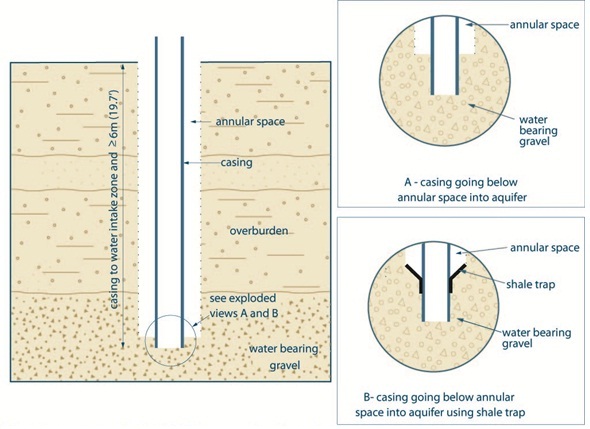
The left side of Figure 5-24 shows a cross-sectional diagram of a drilled well in overburden without using a well screen.
The diagram shows a well completed into gravel overburden. The well is completed with a casing that extends vertically through overburden into gravel overburden. The casing extends from the water intake zone to above the ground surface. There is text adjacent to the casing on the diagram. The text indicates that the casing is required to extend from the ground surface to at least 6 metres (19.7 feet) below the ground surface. There is an annular space around the outside of the casing from the ground surface to the top of the gravel.
There is a circle drawn around the bottom of the well that includes the bottom of the casing and the overburden near the casing on diagram on the left side of Figure 5-24. There is text that states “see exploded views A and B” with an arrow from the text to the circle.
The two exploded views (A and B) are located on the right side of Figure 5-24.
Exploded View A shows a cross-sectional diagram of the bottom portion of the casing driven into an aquifer. The diagram shows the bottom of the well completed with a casing. The bottom of the casing is installed into the water bearing gravel overburden. There is an annular space around the outside of the casing above the gravel overburden.
Exploded View B shows a cross-sectional diagram of the bottom portion of the casing driven into an aquifer and a shale trap attached. The diagram shows the bottom of the well completed with a casing. The bottom of the casing is open to the formation. The bottom of the casing is installed into the water bearing gravel overburden. A shale trap is located around the outside of the casing and close to the bottom of the casing. There is an annular space around the outside of the casing and immediately above the shale trap.
- The casing must extend ≥ 6 m (19.7ft) below ground surface unless the only useful aquifer is < 6 m (19.7ft) below ground surface in which case:
- the casing must extend at least 2.5 m (8.2ft) below ground surface, and
- the well depth must be ≥ 3 m (10 ft) below ground surface.
- The hole diameter must be least 7.6 cm (3 inches) greater than the final outer casing for at least 6 m (19.7ft) from the ground surface or the full depth of teh well (whichever is less).
- If centralizers are used with rotary equipment or a breakaway guide is used with cable tool equipment, the hole diameter must be at least 5.1 cm (2 inches) greater than the final outer casing for at least 6 m (19.7ft) from the ground surface or the full depth of the well (whichever is less).
- This applies to all wells other than wells constructed by the use of a driven or jetted point, dug wells and bored wells with concrete casing.
- In this example, the casing has been driven below the bottom of teh annular space.
Reminder: Refer to Table 5-11 in this chapter for a picture of a shale trap.
Reminder: The diagram above is not to scale and is for illustrative purposes for this chapter only, and does not necessarily represent full compliance with the requirements found in the Wells Regulation.
Figure 5-25: Examples Of Drilled Wells In Bedrock
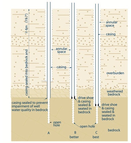
Figure 5-25 shows a cross-sectional diagram of three wells (A, B and C) completed in bedrock.
The three wells are drilled through a layer of overburden underlain by weathered bedrock. The weathered bedrock is underlain by solid (or consolidated) bedrock.
The well on the left of the diagram is example “A”. The well is completed with a casing that extends vertically from above the ground surface through overburden to the top bedrock. The bottom of the casing is sealed into the bedrock immediately below the weathered bedrock to prevent impairment of the well water quality in the bedrock. The well is drilled into the solid bedrock as an open hole as the bedrock has enough strength to not collapse into the hole. There is an annular space around the outside of the casing from the ground surface to an elevation above the top of the weathered bedrock in the overburden.
The well in the middle of the diagram is example “B” and is considered “better” than example “A”. The well is completed with a casing that extends vertically from above the ground surface through overburden to the top bedrock. Unlike scenario A, a drive shoe (thicker piece of casing) is attached to the bottom of the casing and it is the driveshoe that is seated and sealed in the bedrock but immediately below the weathered zone. Beyond the casing and the driveshoe, the well is drilled into the solid bedrock as an open hole as the bedrock has enough strength to not collapse into the hole. There is an annular space around the outside of the casing from the ground surface to the top of the consolidated rock.
The well on the right side of the diagram is example “C” and is considered the “best” of examples “A”, “B” and “C”. The well is completed with a casing that extends vertically from above the ground surface through overburden to the bedrock. A drive shoe (thicker piece of casing) is attached to the bottom of the casing string. The bottom of the casing, with the drive shoe, is sealed and seated into the solid bedrock. Below the casing, the well is drilled into the solid bedrock as an open hole as the bedrock has enough strength to not collapse into the hole. There is an annular space around the outside of the casing from the ground surface to just above the bottom of the drive shoe.
- The casing must extend to ≥ 6 m (19.7ft) below ground surface unless the only useful squifer is < 6 m (19.7ft) below ground surface in which case:
- the casing must extend at least 2.5 m (8.2 ft) below ground surface, and
- the well depth must be ≥ 3 m (10 ft) below ground surface.
- The hole diameter must be at least 7.6 cm (3 inches) greater than the final outer casing for at least 6 m (19.7ft) from the ground surface or the full deth of the well (which is elss).
- If centralizers are used with rotart equipment or a breakaway guide is used with cable tool equipment, the hole diameter must be at least 5.1 cm (2 inches) greater than the final outer casing for at least 6 m (19.7ft) from the ground surface or the full depth of the well (whichever is less.)
- This applies to all wells otehr than wells constructed by the use of a driven or jetted point, dug wells and bored wells with concrete casing.
- In the example, the casing in “A” has been driven below the bottom of the annular space.
Reminder: The diagram above is not to scale and is for illustrative purposes for this chapter only, and does not necessarily represent full compliance with the requirements found in the Wells Regulation.
Reminder: To verify the casing is sealed into the bedrock see the “Best Management Practice – Ensuring the Casing is Sealed in the Bedrock” of this chapter.
Figure 5-26: Drilled Well in Overburden - Natural Development, Casing Pull-Back Method to Expose Well Screen
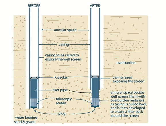
Figure 5-26 shows a cross-sectional diagram of a drilled well in the overburden using natural development, casing pulled back method. Figure 5-26 shows two steps.
The first step (Before) is shown on the left side of the diagram. The diagram shows a hole is extending vertically into a water-bearing sand and gravel deposit in the subsurface. A casing extends from above the ground surface to the bottom of the hole. An annular space is located between the outside of the casing to the side of the hole. A well screen is shown within the bottom of the casing. The well screen is made up of a K-packer, riser pipe, telescopic screen, coupling and plug. The K-packer is located at the top of the well screen and seals the inner casing and well screen. The riser pipe extends downward from the K-packer to a screen. The screen is located below the riser pipe. The coupling and plug are located below the screen.
The second step (After) is shown on the right side of the diagram. The diagram shows a hole extending vertically into the subsurface. A casing extends from above the ground surface into the subsurface. An annular space is located beside the outside of the casing to the side of the hole. A well screen is shown within the bottom of the casing and extends out of the bottom of the casing into the subsurface. The well screen is made up of a K-packer, riser pipe, telescopic screen, coupling and plug. The K-packer is located at the top of the well screen and seals the inner casing and well screen. The riser pipe extends from the K-packer to below the bottom of the casing in the subsurface. The screen is located below the riser pipe in the subsurface. The coupling and plug are located below the screen. A portion of the riser pier, the telescopic screen and plug are located beyond the bottom of the casing allowing groundwater to enter into well through the screen.
There is text associated with the second step that states “casing raised exposing the screen” and “annular space beside well screen fills in with overburden materials as casing is pulled back, and is then developed to create a filter pack around the screen”.
- The casing must extend to ≥ 6 m (19.7ft) below ground surface unless the only useful aquifer is < 6 m (19.7ft) below ground surface in which case:
- the casing must extend at least 2.5 m (8.2 ft) below ground surface, and
- the well depth must be ≥ 3 m (10 ft) below ground surface.
- The hole diameter must be at least 7.6 cm (3 inches) greater than the final outer casing for least 6 m (19.7ft) from the ground surface or the full depth of the well (which is less.)
- If centralizers are used with rotary equipment or a breakaway guide is used with cable tool equipment, the hole diameter must be at least 5.1 cm (2 inches) greater than the final outer casing for at least 6 m (19.7ft) from the ground surface or the full depth of the well (whichever is less).
Reminder: The diagram above is not to scale and is for illustrative purposes for this chapter only, and does not necessarily represent full compliance with the requirements found in the Wells Regulation.
Figure 5-27: Bored Well With Concrete Casing
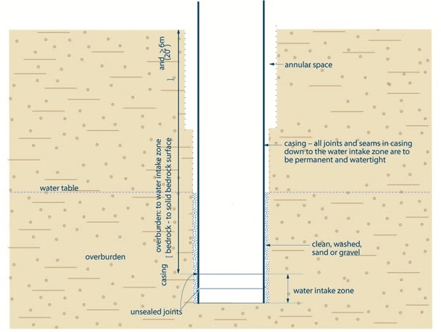
Figure 5-27 shows a cross-sectional diagram of a bored well with concrete casing completed into overburden.
The bored well extends into the subsurface below the water table as represented by a dotted horizontal line. The bored well consists of concrete tiles, arranged vertically on top of one another, from above the ground surface into an aquifer in the overburden. The joints and seams in the concrete tiles are required to be permanently watertight to the water intake zone. These concrete tiles with sealed joints are considered casing. The diagram shows two concrete tiles in the water intake zone that are unsealed. There is text adjacent to the casing on the diagram. The text indicates that the casing is required to extend from the ground surface to at least 6 metres (19.7 feet) below the ground surface. If the well extends into the bedrock, the casing is required to extend to the competent bedrock surface. There is an annular space around the concrete tiles including the unsealed tiles (water intake zone or well screen). The annular space from the water table to the bottom of the concrete tiles is filled with cleaned wash sand or gravel. The clean washed sand and gravel can be no closer than 6 metres (19.7 feet) to the ground surface.
- The casing must extend ≥ 6 m (19.7ft) below ground surface unless the only useful aquifer is < 6 m (19.7ft) below ground surface in which case:
- the casing must extend at least 2.5 m (8.2 ft) below ground surface, and
- the well depth must be ≥ 3 m (10 ft) below ground surface.
- The hole must be at least 15.2 cm (6 inches) greater than the casing’s outer diameter from the land surface to a depth of 2.5 m (8.2 ft).
- The hole must be at least 7.6 cm (3 inches) greater than the casing’s outer diameter from 2.5 m (8.2 ft) to at least 6 m (20 ft) below the ground surface or the full depth of the well (whichever is less)
- Sand and gravel must be installed from at least the top of the water intake zone or screen to no closer than 6 m (20ft) below the land surface unless the only useful aquifer available necessitates a shallower well in which case clean, washed sand or gravel must be installed no closer than 2.5 m (8.2 ft) from the ground surface.
Reminder: The diagram above is not to scale and is for illustrative purposes for this chapter only, and does not necessarily represent full compliance with the requirements found in the Wells Regulation.
Figure 5-28: Dug Well
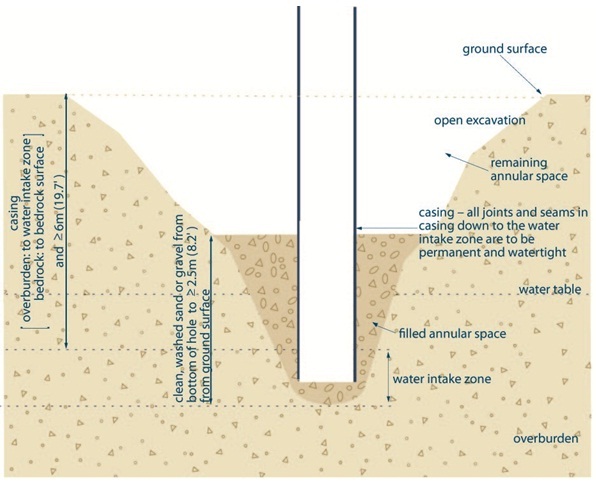
Figure 5-28 shows a cross-sectional diagram of dug well.
The diagram shows a dug well completed into overburden. The well consists of casing that extends vertically from above the ground surface to below the water table in the overburden. The joints and seams in the casing are required to be permanently watertight to the water intake zone. The diagram shows an unsealed joint between two pieces of casing in the water intake zone. The bottom of the casing is open to the formation. There is text adjacent to the casing on the diagram. The text indicates that the casing is required to extend from the ground surface to at least 6 metres (19.7 feet) below the ground surface. The text also indicates that if the well extends into the bedrock, the casing is required to extend to the competent bedrock surface. An area below the casing is filled with clean, washed sand or gravel. There is an annular space around the outside of the casing. The annular space from the bottom of the casing to 2.5 metres (8.2 feet) below the ground surface is filled with clean, washed sand or gravel.
- The casing must extend ≥ (19.7ft) below ground surface unless the only useful aquifer is < 6 m (20ft) below ground surface in which case:
- the casing must extend at least 2.5 m (8.2 ft) below ground surface, and
- the well depth must be ≥ 3 m (10 ft) below ground surface.
- All concrete titles with joints that are not sealed and are installed to filter out particulate matter considered well screen (water intake zone).
- Sand or gravel can be replaced with native material (soil) that was excavated from the hole, if the well is not constructed in a contaminated area and the horizons of soil are excavated separately, stored separately, kept free from contamination and backfilled in the same relative positions that they orginally occupied.
Reminder: The diagram above is not to scale and is for illustrative purposes for this chapter only, and does not necessarily represent full compliance with the requirements found in the Wells Regulation.
Figure 5-29: Driven Point Well
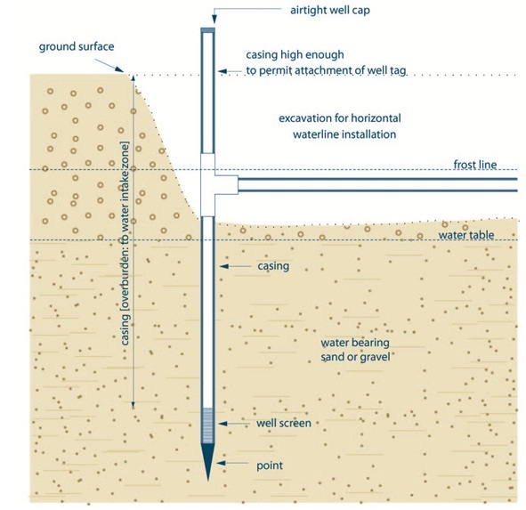
Figure 5-29 shows a cross-sectional diagram of driven-point well.
The diagram shows a driven-point well completed into the subsurface. The well consists of casing that extends vertically from above the ground surface to below the water table in the water bearing sand and gravel overburden. The casing extends to the water intake zone. A well screen is attached to the bottom of the casing and a drive-point is attached to the bottom of the well screen. An airtight cap is located at the top of the casing. The casing is high enough above the ground surface to affix a well tag above the ground surface. Below the frost line a horizontal water line connects to the casing. An excavation zone has been created to connect the horizontal waterline to the casing.
- The casing must extend ≥ 6 m (19.7ft) below ground surface unless the only useful aquifer is < 6 m (19.7ft) below ground surface in which case:
- the casing must extend at least 2.5 m (8.2 ft) below ground surface, and
- the well depth must be ≥ 3 m (10 ft) below ground surface.
Reminder: The diagram above is not to scale and is for illustrative purposes for this chapter only, and does not necessarily represent full compliance with the requirements found in the Wells Regulation.
Figure 5-30: Jetted Well
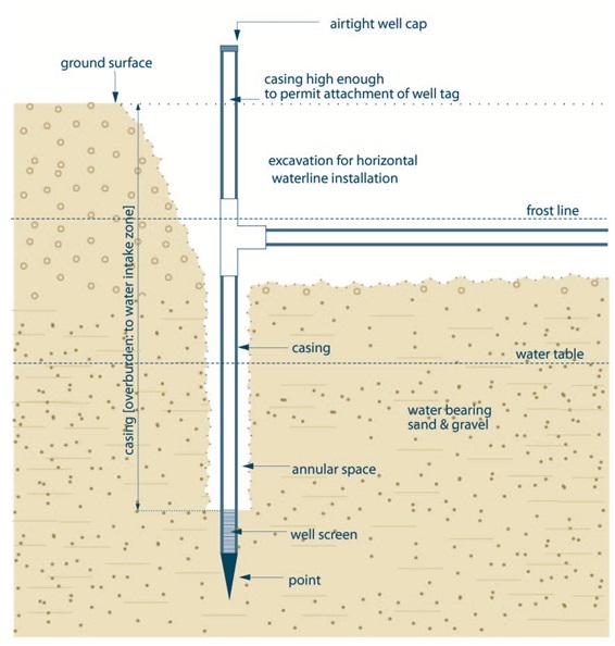
Figure 5-30 shows a cross-sectional diagram of a jetted point well.
The diagram shows a jetted point well completed into the overburden. The well consists of casing that extends vertically from above the ground surface to below the water table in the water bearing sand and gravel overburden. The casing extends to the water intake zone. A well screen is attached to the bottom of the casing and a drive-point is attached to the bottom of the well screen. An airtight well cap is located at the top of the casing. The casing is high enough above the ground surface to affix a well tag above the ground surface. Below the frost line a horizontal water line connects to the casing. An excavation zone has been created to connect the horizontal waterline to the casing.
- The casing must extend ≥ 6 m (19.7ft) below ground surface unless the only useful aquifer is < 6 m below ground surface in which case:
- the casing must extend at least 2.5 m (8.2 ft) below ground surface, and
- the well depth must be ≥ 3 m (10 ft) below ground surface.
Reminder: The diagram above is not to scale and is for illustrative purposes for this chapter only, and does not necessarily represent full compliance with the requirements found in the Wells Regulation.
Footnotes
- footnote[1] Back to paragraph Modified from: McKenna, F. P, and Ontario Ministry of the Environment. 1987. Water Wells and Ground Water Supplies in Ontario. Queens Printer Press for Ontario. Table 2, page 16.
- footnote[2] Back to paragraph Modified from: US Army Corp of Engineers. November 1, 1998. Monitoring Well Design at Hazardous, Toxic, and Radioactive Waste Sites (EM 1110-1-4000) Table 3-1, page 3-3.
- footnote[3] Back to paragraph Modified from: Fleming College. 2008. Manual for Continuing Education Course Monitoring Wells – Construction (for Ontario Well Technicians): Table 6, page 64.
- footnote[4] Back to paragraph Modified from: Sterrett, Robert J. 2007. Groundwater and Wells: Third Edition. Johnson Screens/a Weatherford Company. New Brighton, Minnesota. Table 7.3, page 283.
- footnote[5] Back to paragraph Nielsen, David M. 2006. Practical Handbook of Environmental Site Characterization and Ground-water Monitoring: Second Edition. CRC – Taylor & Francis Group. Boca Raton, FL.
- footnote[6] Back to paragraph Powers, J. Patrick, Arthur B. Corwin, Paul C. Schmall and Walter E. Kaeck. 2007. Construction Dewatering and Groundwater Control – New Methods and Applications: Third Edition. John Wiley and Sons Inc., Hoboken, NJ.
- footnote[7] Back to paragraph Fleming College. 2008. Course Manual for Well Constructed: Training for Assistant Well Technicians in Ontario. Chapter 7, Figure 7-7.
- footnote[8] Back to paragraph Occupational Health and Safety Act, R.S.O. 1990, Chapter 0.1, Ontario Regulation 213/91: Construction Projects.
- footnote[9] Back to paragraph Fleming College. 2008. Course Manual for Well Constructed: Training for Assistant Well Technicians in Ontario. Chapter 3, Table 3-9.
- footnote[10] Back to paragraph Tucker, Maurice, E. 2003. Sedimentary Rocks in the Field. John Wiley and Sons Ltd. ISBN: 0-470-85123-6. Page 69, Table 4.2.
- footnote[11] Back to paragraph American Water Works Association (AWWA). 2003. ANSI/AWWA C 654-03 - Disinfection of Wells. AWWA, Denver, CO. 2003. AWWA website.
- footnote[12] Back to paragraph NSF International Standard/American National Standard 61, 2008. Water Treatment and Distribution Systems - Health Effects. NSF International, Ann Arbor, MI 2008. NSF website: Certified fibre-reinforced plastic casing for potable water use (see NSF Products and Service Listings).
- footnote[13] Back to paragraph World Health Organization. 2006. Guidelines for Drinking-water Quality, First Addendum to the Third Edition, Volume 1, Recommendations - 3rd Edition, ISBN 92 4 154696 4 (NLM Cassification: WA 675). Pages 181, 182, 183 and 219
- footnote[14] Back to paragraph ASTM Standard ASTM C478-07 (2009). “Standard Specification for Precast Reinforced Concrete Manhole Sections” ASTM International, West Conshohocken, PA, 2009, DOI: 10.1520/C0478-07, ASTM website
- footnote[15] Back to paragraph ASTM Standard C990M, 2006 (2009). Specification for Joints for Concrete Pipe, Manholes, and Precast Box Sections Using Preformed Flexible Joint Sealants. ASTM International, West Conshohocken, PA, 2009, DOI: 10.1520/C0990-09, ASTM website.
- footnote[16] Back to paragraph (DOI: 10.1520/C0990-09). ASTM International, West Conshohocken, PA, ASTM website
- footnote[17] Back to paragraph (DOI: 10.1520/F0480-06BE01). ASTM International, West Conshohocken, PA, ASTM website
- footnote[18] Back to paragraph Sterrett, Robert J. 2007. Groundwater and Wells: Third Edition. Johnson Screens/ a Weatherford Company. St. Paul, Minnesota.
- footnote[19] Back to paragraph McCarthy, David F. 1998. Essentials of Soil Mechanics and Foundations – Basic Geotechnics: Fifth Edition. Prentice Hall. Upper Saddle River, New Jersey. Page 96.
- footnote[20] Back to paragraph Sterrett, Robert J. 2007. Groundwater and Wells: Third Edition. Johnson Screens/a Weatherford Company. St. Paul, Minnesota. Table 9.17, Page 411.
- footnote[21] Back to paragraph Sterrett, Robert J. 2007. Groundwater and Wells: Third Edition. Johnson Screens/ a Weatherford Company. St. Paul, Minnesota.
- footnote[22] Back to paragraph ASTM Standard ASTM C478-13 (2013). Standard Specification for Precast Reinforced Concrete Manhole Sections. ASTM International, West Conshohocken, PA, 2009, DOI: 10.1520/C0478-07, ASTM website.
- footnote[23] Back to paragraph ASTM Standard C990M, 2009 (2009). Specification for Joints for Concrete Pipe, Manholes, and Precast Box Sections Using Preformed Flexible Joint Sealants. ASTM International, West Conshohocken, PA, 2009, DOI: 10.1520/C0990-09, ASTM website.
- footnote[24] Back to paragraph Sterrett, Robert J. 2007. Groundwater and Wells: Third Edition. Johnson Screens/ a Weatherford Company. St. Paul, Minnesota. Pages 483-485.
- footnote[25] Back to paragraph Sterrett, Robert J. 2007. Ground water and Wells: Third Edition. Johnson Screens/ a Weatherford Company. St. Paul, Minnesota. Pages 467-468.
- footnote[26] Back to paragraph Sterrett, Robert J. 2007. Ground water and Wells: Third Edition. Johnson Screens/ a Weatherford Company. St. Paul, Minnesota. Page 491.
- footnote[27] Back to paragraph Sterrett, Robert J. 2007. Ground water and Wells: Third Edition. Johnson Screens/ a Weatherford Company. St. Paul, Minnesota. Page 491
- footnote[28] Back to paragraph Sterrett, Robert J. 2007. Ground water and Wells: Third Edition. Johnson Screens/ a Weatherford Company. St. Paul, Minnesota. Page 470.
- footnote[29] Back to paragraph Sterrett, Robert J. 2007. Groundwater and Wells: Third Edition. Johnson Screens/a Weatherford Company. St. Paul, Minnesota. Page 478.