Part C - Method ON-2: Determination of Stack Gas Velocity and Volumetric Flow Rate
Part C: Method ON-2: Determination of Stack Gas Velocity and Volumetric Flow Rate
1.0 Purpose
To determine the velocity profile, the average gas velocity and volumetric flow rate in a stack or duct. The method is based on the measurement of the velocity pressure heads and stack gas temperatures. It takes into consideration the stack gas molecular weight, pressure and the configuration of the stack or duct.
2.0 Limitations
The basic method is not applicable in the following cases:
- cyclonic or reverse flow (see Part B: Method ON-1);
- gas velocity pressure too low to be accurately measured with an inclined manometer or device of equivalent sensitivity; and,
- fluctuating velocity pressure readings.
Where any of the above situations occur, reference should be made to the appendices.
3.0 Apparatus
- Pitot tube – S-type (Stausscheibe or reverse type) Pitot tube. Alternatively, a standard Pitot tube may be used where particulate matter or condensate plugging of the static and impact pressure holes will not occur. Figures 2-1 and 2-2 show a typical configuration of Standard and S-Type Pitot tubes respectively.
- Differential pressure gauge – Inclined manometer or device of equivalent sensitivity, readable to the nearest 0.10 mm H2O for velocity pressure (ΔP) values between 0.10 mm and 25 mm H2O and readable to the nearest 1.0 mm H2O for ΔP values greater than 25 mm H2O. A more sensitive gauge is required if a ΔP reading covers less than five (5) smallest scale divisions. See Chapter 7.3, Appendix 2C regarding more sensitive gauges.
- Temperature sensor – Thermocouple or other calibrated device capable of measuring stack gas temperature to within 1.5% of the minimum gas temperature. Temperature sensor must be checked according to the procedure outlined in Chapter 7.5, Appendix 2E.
- Probe – The combination of a calibrated Pitot tube and temperature sensor rigidly fixed to a sampling probe, facilitating simultaneous measurement of temperature and velocity pressure head at each point during sampling. The configuration of this combination is shown in Figure 2-3.
Note: The sampling probe can be omitted when the stack gas velocities only are measured; however, this combination of temperature sensor fixed to the Pitot tube must be calibrated separately.
- Stack Gas Pressure Sensor – The static tap of a standard Pitot tube or one leg of an S-type Pitot tube, with the face opening planes positioned parallel to the gas flow, connected to a manometer capable of measuring stack pressure to within 2.5 mm Hg or equivalent devices.
- Barometer – Barometer capable of measuring atmospheric pressure to within 2.5 mm Hg. Alternatively, the daily atmospheric pressure as provided by Environment Canada may be used with an altitude adjustment being made for the elevation of the sampling site at a rate of 2.5 mm Hg per 30 meters of elevation increase or vice versa for elevation decrease.
4.0 Procedure
- Use a Pitot tube calibrated exactly as it will be used (alone or as part of a probe assembly: thermocouple, sheathing and nozzles that will be used in sampling). The Pitot tube must be calibrated in accordance with the American Society for Testing and Materials (ASTM) Standard Practice D3796-09 “Practice for Calibration of Type S Pitot tubes”, or its most recent version. Additional information is also found in Chapter 7.1, Appendix 2A.
Before each test, the Pitot tube must be examined to determine if it has incurred any damage, especially to its leading edge. If damaged, or if there is noticeable but non-removable particulate build-up, it must either be repaired or replaced, and in either case, recalibrated.
Also, if the Pitot tube has shifted in position relative to the other components of the probe assembly since the last calibration, the Pitot must be recalibrated before use or repositioned exactly.
- Conduct a leak-check of the Pitot tube and Pitot lines by pressurizing one of the Pitot tube openings until a minimum pressure head of 75 mm H2O is registered on the differential pressure gauge. Seal off the selected Pitot tube opening and verify that the pressure remains constant. Similarly, leak-check the other Pitot tube openings.
- Level and zero the manometer. Since the manometer level and zero may drift due to vibration and temperature changes, periodic checks of the manometer level and zero must be made during the measurement. All data are to be recorded according to the format shown in Table 2-1. If a differential pressure gauge other than a manometer is used, it must be calibrated every 6 months, in accordance with Chapter 7.2, Appendix 2B.
- Determine the stack gas static pressure by connecting one leg of the manometer to the static tap of a standard Pitot tube or to one leg of an S-type Pitot tube with the face opening planes positioned parallel to the gas flow. This reading may be positive or negative depending on the conditions in the stack or duct. Determine the atmospheric pressure using the barometer. The static pressure reading, if necessary, is converted to the units of the atmospheric pressure reading and added to that pressure to give the absolute stack gas pressure, in accordance with Equation 2-1.
- The velocity pressure (ΔP) and temperature are measured at each sampling point. Ensure the face opening planes of the S-type Pitot tube are maintained perpendicular to the cross-sectional plane of the stack or duct. The velocity pressure tap of the standard Pitot tube or the face opening planes of the S-type Pitot are maintained perpendicular to the longitudinal axis of the stack or duct. If a ΔP reading is less than 5 smallest scale divisions, a more sensitive gauge must be used at that point (See Chapter 7.3, Appendix 2C).
- If a ΔP reading fluctuates more than ±20% of the average value at a point, during the preliminary survey, the stack gas flow needs to be stabilized before proceeding with the testing. If these reading fluctuations start during sampling, the test should be stopped until the source of the fluctuations are determined. If the stack gas flow can be stabilized, the test may proceed; otherwise, the test should be abandoned.
Note: If ΔP reading fluctuates more than ±20% of the average value at a point, the data gathered is unacceptable.
If the high velocity reading fluctuations persist, contact the Ministry’s Source Assessment Specialist to discuss possible solutions. See Chapter 7.4, Appendix 2D for additional comments on velocity reading fluctuations. - Calculate the stack gas velocity at each sampling point according to Equation 2-2. Calculate the stack gas volumetric flow rate using Equation 2-3.
5.0 Equations for Method ON-2
Equation 2-1
Ps = Pbar + 0.098Pstatic
Where:
- Ps
- absolute stack gas pressure, kPa
- Pbar
- atmospheric pressure, kPa
- Pstatic
- stack gas static pressure, cm H2O
- 0.098
- factor to convert cm H2O to kPa
Equation 2-2
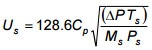
Where:
- Us
- stack gas velocity (at a point), m/s
- Cp
- Pitot tube coefficient
- Ts
- absolute stack gas temperature, K
- ΔP
- stack gas velocity pressure head, kPa
- Ms
- stack gas molecular weight - wet basis, kg/kmol
- Ps
- absolute stack gas pressure, kPa
Equation 2-3
Qs = 3600Us(avg) As(1 − Bwo) [(TrefPs) ⁄ (Ts(avg) Pref)]
Where:
- Qs
- stack gas volumetric flow rate (dry basis at reference conditions), m3/h
- Us(avg)
- average stack gas velocity, m/s (average of Us's determined at each point)
- As
- cross-sectional area of stack or duct, m2
- Bwo
- proportion of water in stack gas
- Tref
- 298K
- Ts(avg)
- average stack gas temperature, K (average of Ts's determined at each point)
- Ps
- absolute stack gas pressure, kPa
- Pref
- 101.3 kPa
6.0 Discussion of Method ON-2
6.1 Purpose
This method is applied in all cases of representative measurement of enclosed gas flows. Given the gas composition as determined in Parts D and E (Methods ON-3 and ON-4), with this method the gas velocity is determined at each point of a cross-sectional area as defined in Part B (Method ON-1). The average velocity of the stack gas and an overall stack gas volumetric flow rate are then calculated.
6.2 Limitations
6.2.1 Cyclonic or Reverse Flow
Method ON-2 is not applicable if cyclonic or reverse flow is present at the sampling location. The method requires that the flow at the sampling point be reasonably parallel to the longitudinal axis of the stack or duct and in the general direction of the gas stream. If cyclonic flow is suspected, its presence is confirmed by the procedure outlined in Part B (Method ON-1).
6.2.2 Low Gas Velocity
This method is also not applicable in situations where the gas velocity is so low that the differential pressure gauge is unable to accurately measure the velocity pressure head; the limit is five (5) smallest scale divisions. For most manometers on stack sampling units, this limit is 1.0 mm H2O, which corresponds to about 3.0 m/s for an ambient air stream at ambient temperature. Reference should be made to Chapter 7.3, Appendix 2C, concerning more sensitive pressure gauges.
6.2.3 Fluctuating Gas Velocity
A further limitation to the applicability of Method ON-2 occurs in cases where the stack gas velocity fluctuates significantly, i.e., ΔP readings at a point vary more than ±20% of the estimated average ΔP reading. A 20% error with respect to ΔP represents approximately a 10% error in the velocity calculation. At lower velocities, the inaccuracy of a fluctuating reading is compounded by the greater relative error associated with reading the pressure gauge at the low end of the scale. If severe fluctuations are encountered, reference should be made to Chapter 7.4, Appendix 2D.
It is noted that this method is not limited with respect to sampling site selection criteria in relation to upstream and downstream flow disturbances outlined in Part B (Method ON-1); i.e., this method may be used at any point in a flowing gas stream to determine the velocity at that point. However, at points closer to a disturbance, there is a greater likelihood of fluctuating velocities and thus more inaccuracy in the ΔP readings. Thus the same geometrical limitations outlined in Part B (Method ON-1) may be applicable when determining whether or not a given sampling site is satisfactory for representative flow measurements.
7.0 Appendices to Method ON-2
7.1 Appendix 2A: Configuration of Pitot Tubes
7.1.1 Pitot Tube Calibration
For the purposes of Method ON-2 and any other method where a Pitot tube is required, the Pitot tube must be properly calibrated. That is, the Pitot tube must be calibrated exactly as it will be used, i.e., if used as part of a probe assembly (nozzle, temperature sensor and sheathing), the Pitot tube must be similarly fixed in relation to the other components of the assembly for both calibration and usage.
Furthermore, if there is any noticeable, but very minor damage to the Pitot tube openings or if there is noticeable but non-removable particulate build-up, either of which has occurred since the last calibration, the Pitot tube must be recalibrated before use.
The Pitot tube must be calibrated in accordance with the ASTM Standard Practice D3796-09 “Practice for Calibration of Type S Pitot tubes”, or its most recent version.
7.1.2 Compliance Test
In the case of a compliance test, it is mandatory that the most recent Pitot tube calibration data (done within six months) and results be included in any report submitted to the Ministry. These data should be dated and signed by the person(s) performing the calibration.
7.1.3 Pitot Tube Inspection
Prior to use, an inspection should be performed to confirm that the Pitot tube has not been damaged in any manner. If damaged, the Pitot tube must be repaired and recalibrated. If repair is not practical, the Pitot tube shall be discarded.
7.1.4 Probe Assembly
Generally, the probe assembly, including the Pitot tube, will have a similar configuration as shown in Figures 2-3 and 2-4. Both goose-neck (buttonhook) type and 90° bend nozzles may be used except in stacks or ducts with heavy dust loading where only goose-neck nozzles may have to be used. Figures 2-3 and 2-4 indicate recommended spatial requirements so that aerodynamic interference among components of the assembly is minimized. However, these distances may only be slightly exceeded since the function of the probe assembly is to measure stack parameters as close as possible to the point where the sample is drawn into the probe. Figure 2-5 provides graphical details and equation for estimating the probe sheath blockage area.
The temperature sensor is attached so that the sensor tip does not touch any metal. The tip of the nozzle must extend at least two (2) nozzle diameters below the tip of the upstream leg of the S-type Pitot tube. The S-type Pitot tube on a probe assembly can be calibrated with a nozzle of similar shape to the one selected for the testing. Should a nozzle outside of the typical size range be used (i.e., >13mm), pitot tube calibrations need to be completed with a nozzle of similar diameter (within 2mm).
7.2 Appendix 2B: Calibration of Differential Pressure Gauges other than Manometers
The calibration is done by comparing ΔP readings obtained with the gauge and an inclined manometer at a minimum of three (3) different flow velocities which approximate the ΔP's found in the stack or duct. The readings must agree to within 5% at each point for the gauge to be acceptable (see Equation 2-4). Calibration results are reported as shown in Table 2-2.
Equation 2-4
Percent Difference = [(ΔPgauge − ΔPmanometer) ⁄ ΔPmanometer] × 100%
7.3 Appendix 2C: Substitutes for Inclined Manometers in the Case of Low Stack Gas Velocities
As stated in Chapter 3(b), if a ΔP reading is found to be less than five (5) smallest scale divisions on the gauge being used, a more sensitive device must be employed. Such devices include hot wire anemometers, rotating and swinging vane anemometers, and variable area flow meters.
7.4 Appendix 2D: Fluctuating Velocity Pressure Readings
If a ΔP reading fluctuates more than ±20% of the average value at a point, the data gathered at the point are unacceptable. Fluctuation of gas velocity generally does not arise due to stack or duct configuration but rather variations in the process or upstream machinery. If the operation of the process or machinery cannot be stabilized, it may be possible to dampen the fluctuations in velocity by temporarily extending the stack or duct or providing a stack gas expansion chamber before the differential pressure gauge.
7.5 Appendix 2E: Calibration and Check of Temperature Sensors
The temperature sensor must be calibrated according to accepted routine procedures and the calibration values checked every six (6) months. This is done by comparing sensor readings to several known temperatures covering the range expected in the field. The apparatus used for this purpose are an ice bath, boiling water and a heated oil bath with a liquid-filled thermometer. If the sensor readings do not compare within 1.5% of the known absolute temperatures, the sensor must be replaced.
Alternatively, an electronic temperature calibrator may be used for internal calibration of thermocouples. In these cases the electronic temperature calibrator must have a valid calibration certificate, tied to a primary standard. Both calibration records need to be provided upon request by the Ministry, and included in an appendix of each source test report.
8.0 References
- American Society of Testing and Materials, Standard D3796-90(2004), Standard Practice for Calibration of Type S Pitot Tubes, 2004.
- Environment Canada, Reference Method EPS 1/RM/8, Reference Methods for Source Testing: Measurement of Releases of Particulates from Stationary Sources, December, 1993.
- Ministry of Environment and Energy, Province of Ontario, Source Testing Code, Version 2, Report # ARB-66-80, November 1980.
- United States Environmental Protection Agency, Code of Federal Regulations, Title 40 Part 60, Appendix A, July 1. 1994.
Table 2-1: Field Sampling Report Template
Download Field Sampling Report Template.
Table 2-2: Differential Pressure Gauge Calibration Data Template
Download Differential Pressure Gauge Calibration Data Template
Figure 2-1: Typical Standard Pitot Tube Configuration
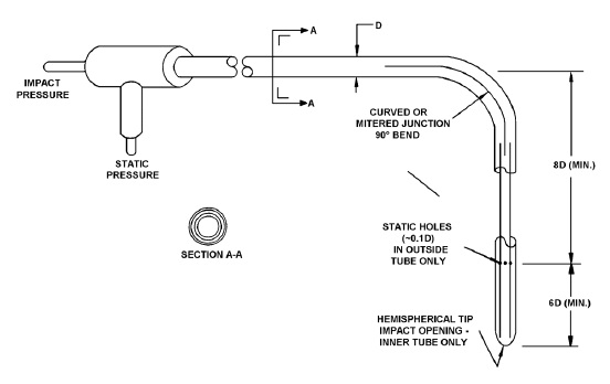
This figure depicts the typical standard pitot tube configuration. It shows a T-junction tube that can be used to measure the impact and static pressure. This T-junction tube is connected to the pitot tube which curves 90 degrees downward and has static holes approximately 0.1 times the diameter. These holes are located at a length at least 8 times the diameter of the pitot tube from the 90 degree bend and at least 6 times the diameter of the pitot tube from the hemispherical tip.
Figure 2-2: Typical S-Type Pitot Tube Configuration
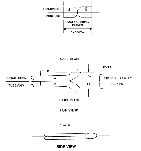
Figure 2-2 depicts a typical s-type pitot tube configuration and includes three views: End view, top view and side view. The end view shows that the two pitot tubes must be aligned along the transverse tube axis with the faces opening in the opposite direction. The top view shows that the pitot tubes are aligned along the longitudinal tube axis and the height of the tubes above this axis is between 1.05 to 1.50 times the diameter of the tubes and they are equal. The side view shows that the pitot tube assembly must be aligned along a plane.
Figure 2-3: Configuration Of Pitot Tube, Sampling Probe, And Thermocouple
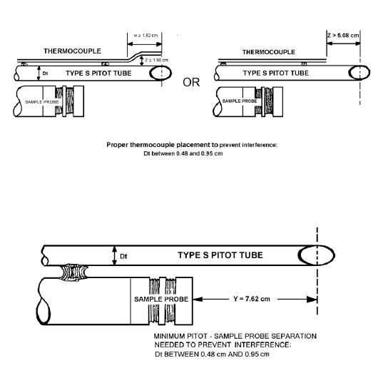
Figure 2-3 shows the combination of a calibrated Pitot tube and temperature sensor rigidly fixed to a sampling probe that facilitates simultaneous measurement of temperature and velocity pressure head at each point during sampling. The proper configuration of the thermocouple placement to prevent interference for pitot tube diameters between 0.48cm and 0.95cm, must ensure that the thermocouple is maintains a distance of at least 1.90 cm from the opening of the pitot tube for at least 1.62cm. Otherwise, if there is no separation distance between the thermocouple and the pitot tube, the thermocouple must be placed no less than 5.08cm from the centre of the pitot tube opening. Another figure is also provided which shows the centre of the pitot tube opening must be at least 7.62cm from the sampling probe to prevent interference when the diameter of the pitot tube is between 0.48cm and 0.95cm.
Figure 2-4: Pitot Tube And Sampling Nozzle Configuration
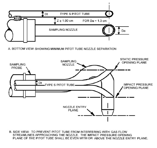
This figure illustrates the pitot tube and sampling nozzle configuration of a Button-Hook type nozzle. The centre of the nozzle and Pitot tube’s opening align and the diameter of the type S pitot tube is between 4.8mm and 9.5mm. There are two views provided to depict this configuration the bottom view and the side view. The bottom view shows that the distance between the pitot tube and sampling nozzle must be greater than 1.9cm, for a sampling nozzle 1.3cm in diameter. The side view shows that, in order to prevent the pitot tube from interfering with gas flow streamlines approaching the nozzle, the impact pressure opening plane of the pitot tube shall be even with or above the nozzle entry plane.
Figure 2-5: Typical Probe Sheath Blockage Area
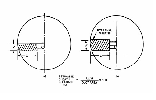
This figure depicts the typical probe sheath blockage area. It features two images titled image (a) and image (b). It also includes the Estimated Sheath Blockage (percentage) equation. Both images depict a close up view of a sampling probe and pitot tube. In image (a) only the sampling probe is encapsulated by a sheath. Whereas, in image (b) both the sampling probe and the pitot tube are encapsulated. Image (b) includes the words “External sheath” which denotes that the sheath encapsulates the temperature sensor and the pitot tube. In both drawings, the length and width of the sheath measured by physical dimensions of the actual size of the sheath whether it encapsulates only the sampling probe or both the sampling probe and pitot tube. The estimated sheath blockage percentage is calculated by multiplying the length and width of the sheath, then dividing this value by the duct area. This results in the percentage estimate of the sheath blockage number once multiplied by 100.