Part F - Method ON-5: Determination of Particulate Emissions from Stationary Sources
Part F: Method ON-5: Determination of Particulate Emissions from Stationary Sources
1.0 Purpose
To determine the particulate matter concentration of a gas stream in a stack or duct and the particulate emission rate, using an isokinetic sampling technique and an out-stack glass fibre filter which is maintained at a temperature of 120°C.
Particulate matter refers to any filterable material, with an aerodynamic diameter between 44 µ and 0.3 µ, that maintains its solid state properties at 120°C, under ambient atmospheric pressure.
Note: The Ministry may require condensable particulate matter to be included in the determination of particulate matter emissions. If condensable particulate matter is required to be tested, it will be clearly indicated by the Ministry in the Certificate of Approval or any other legal document being used by the Ministry.
The Source Assessment Specialist needs to be contacted for guidance, if condensable particulate matter is required to be included in the calculation of particulate matter emissions.
2.0 Limitations
This method is not applicable in the following cases:
- Gas streams containing significant concentrations of one or more substances with a dew point greater than 120°C;
- For condensable matter determination;
- Non-continuous processes;
- Positive pressure baghouses;
- Low particulate matter concentrations (less than 5 mg catch); or
- Cyclonic flow.
Where any of the above situations occur, reference is to be made to Chapter 9 Appendices.
3.0 Apparatus
3.1 Sampling Train
Commercially available sampling trains generally are comprised of the individual components shown in Figure 5-1. Such trains are acceptable for use with this method. Specifically, the required components for this method are:
- Probe Nozzle – Stainless steel (316, seamless), glass or quartz, with a sharp, tapered leading edge; button-hook or elbow design. A range of nozzles should be available to allow for isokinetic sampling at sources with different gas velocities, e.g., 0.3175cm to 1.270cm.
- Probe – Structurally stable, long enough to traverse at least half of the stack diameter, capable of maintaining a gas temperature of 120°C at the exit end during sampling and including a probe temperature sensor. The probe is lined with borosilicate or quartz glass, if the stack temperature is less than 480°C. However, the probe is lined with quartz glass, if the stack temperature is more than 480°C and less than 900°C. For stack gas temperatures lower than 250°C, a Teflon liner may be used where length and strength limitations prevent the use of glass or quartz, or corrosion resistant metal liners for higher temperatures (Probe is usually sheathed for protection and insulation and water cooled, if required).
- Pitot tube – S-type (Stausscheibe or reverse type) or standard type. Reference should be made to Part C (Method ON-2) concerning Pitot tube and probe assembly (Pitot tube, temperature sensor and nozzle) configuration and calibration.
- Temperature Sensor – Thermocouple or other calibrated device capable of measuring stack gas temperature to within 1.5% of the minimum temperature. Temperature sensor is fixed to the probe assembly so that the tip of the sensor extends beyond the probe sheath and does not touch any metal. The temperature sensor must be checked according to the procedure outlined in Part C (Method ON-2, Chapter 7.5, Appendix 2E).
- Differential Pressure Gauges – Two inclined manometers or devices of equivalent sensitivity, readable to the nearest 0.10 mm H2O for ΔP values between 0.10 and 25 mm H2O and readable to the nearest 1.0 mm H2O for ΔP values greater than 25 mm H2O. A more sensitive gauge is required if a ΔP reading is found to be less than five (5) smallest scale divisions. See Part C (Method ON-2, Chapter 7.2, Appendix 2B) regarding calibration of differential pressure gauges other than manometers and Part C (Method ON-2, Chapter 7.3, Appendix 2C) regarding more sensitive gauges.
- Filter Holder – Borosilicate glass with a glass or sintered stainless steel frit filter support and silicone rubber gasket (other inert materials may be used); designed to avoid leakage around the filter.
- Miniature Cyclone – Optional, although it should be used when the particulate catch is expected to exceed 100 mg.
- Filter and Cyclone Heating System – Capable of maintaining a temperature of 120°C around the filter holder and cyclone (if used) during sampling and including a temperature gauge capable of measuring to within 1°C to enable monitoring and regulation of the temperature.
- Condenser – Comprising of four impingers connected in series with leak-free fittings (e.g., ground glass). The first, third and fourth impingers are of the Greenburg-Smith design modified by replacing the tip with 1.3cm I.D. glass tubing extending to about 1.3cm from the bottom of the flask. The second impinger is of the standard Greenburg-Smith design. A temperature sensor capable of measuring temperature to within 1°C is placed at the outlet of the fourth impinger. Known volumes of water are placed in the first and second impingers and a known weight of desiccant is placed in the fourth impinger. The impingers are maintained in an ice bath. Alternatively, functionally equivalent systems are acceptable.
- Metering System – Comprising of a vacuum gauge, leak-free pump with coarse and fine control valves, calibrated dry gas meter capable of measuring volume to within 2% and including an inlet and an outlet temperature sensor capable of measuring temperature to within 1°C or temperature compensation and a calibrated orifice meter.
- Barometer – Mercury aneroid or other barometer capable of measuring atmospheric pressure to within 2.5 mm Hg. Alternatively, the daily atmospheric pressure as provided by Environment Canada may be used with an altitude adjustment for the sampling site at the rate of minus 2.5 mm Hg per 30 meters of elevation increase or vice versa for elevation decrease.
- Gas Composition Determination Equipment – See Parts D and E (Methods ON-3 and ON-4).
3.2 Sample Recovery and Analysis Equipment
- Brushes – Sized and shaped to clean out probe and nozzle; nylon bristles with stainless steel wire handle and extensions of stainless steel, Nylon, Teflon, or other inert material.
- Wash Bottles – Glass or polyethylene; acetone should not be stored in polyethylene bottles for longer than one month.
- Liquid Sample Storage Containers – Glass or polyethylene (500 or 1000 ml) with leak-free acetone resistant caps. Acetone samples should not be stored in polyethylene longer than one month.
- Petri Dishes – Glass or polyethylene, large enough to hold an unfolded filter.
- Graduated Cylinder – With subdivisions no greater than 2 ml.
- Balance – Capable of weighing to the nearest 0.5 g.
- Desiccant Containers – Air tight.
- Funnel and Rubber Policeman.
- Dessicator.
- Analytical Balance – Capable of weighing to the nearest 0.1 mg.
4.0 Reagents And Materials
4.1 Sample Collection
The following items are required for sample collection:
- Filters – glass fibre without organic binder, exhibiting at least 99.95% efficiency (<0.05% penetration) on 0.3 micron dioctyl phthalate smoke particles (manufacturer’s test data are sufficient).
- Water – distilled or de-ionized. Run blank prior to field use to eliminate a high background on test samples.
- Silica Gel – new or fully regenerated, 6 to 16 mesh indicating type. To regenerate silica gel, dry at 175°C for 2 hours.
- Stopcock Grease – heat-stable silicone grease insoluble in acetone.
- Crushed Ice.
4.2 Sample Recovery
The following items are required for sample recovery:
- Acetone – reagent grade, 0.001% residue, in glass bottles.
- Water – distilled or de-ionized. Run blank prior to field use to eliminate a high background on test samples.
4.3 Sample Analysis
The following items are required for sample analyses:
- Acetone – reagent grade, 0.001% residue, in glass bottles.
- Desiccant – new or fully regenerated, self-indicating, e.g., 6 to 16 mesh indicating type silica gel, anhydrous calcium sulphate.
5.0 Procedure
5.1 Sampling Equipment Preparation
- The Pitot tube (probe assembly), dry gas meter and orifice meter must be maintained in accordance with standard accepted procedures and calibrated prior to testing, in accordance with the procedures specified in Part C (Method ON-2, Chapter 7.1, Appendix 2A) and Part E (Method ON-4, Chapter 6.2, Appendix 4B). Such calibration data must be available on request, prior to or during the actual testing and also must be submitted with the final report.
- Filters are checked visually against a light for irregularities and flaws or pinhole leaks. They are identified by appropriate labelling of their shipping containers (Petri dishes).
- Filters are desiccated at 20°C ±6°C and ambient pressure for at least 24 hours and then weighed at intervals of at least 6 hours to a constant weight, i.e., 0.5 mg change from the previous reading. Weight of filters is recorded to the nearest 0.1 mg. Record the filter weighing room relative humidity which must not exceed 50% during weighing. The filter should not be exposed to the ambient atmosphere for longer than 2 minutes.
- Weigh the cyclone collection flask, if used, and record the weight to the nearest 0.1 mg.
- Select the sampling site location and number of sampling points in accordance with Part B (Method ON-1).
5.2 Preliminary Survey
A preliminary survey must be performed to determine gas flow parameters in order to prepare for actual sampling at isokinetic rates. Gas temperature, molecular weight, static pressure and the velocity profile (including cyclonic and reverse flow checks) are required parameters for this purpose. It is also important to know the range of particulate matter loading so that a sampling period can be established.
The parameters noted above can be determined by completing Parts C to F (Methods ON-2 to ON-5). For this purpose, Method ON-5 may be modified. For example, total sampling time may be reduced by decreasing the number of sampling points or the sampling time per point. The information learned from such a test would include the gas temperature, velocity profile, moisture content and particulate matter loading. From this information, assuming the parameters of the source remain constant, isokinetic sampling rates can be calculated and the proper nozzle size determined. Also, the sampling period can be determined so as to meet the minimum criteria for particulate matter catch or total gas volume sampled.
5.2.1 Preliminary Survey Omissions
Portions of the preliminary survey do not have to be performed, if it can be shown that the respective parameters are known to a satisfactory degree of accuracy. Written documentation should be provided.
5.2.2 Nozzle Size
The nozzle size must be selected so that it is not necessary to change the nozzle during the sampling test in order to achieve isokinetic sampling. As well, the probe liner and probe length should be suitable for the conditions of the gas stream and the size of the stack or duct. With very large cross-sections it may be necessary to perform four half-diameter traverses.
5.2.3 Testing Period Criteria
The minimum criteria for the actual testing period are:
- Sampling for five (5) minutes per traverse point, and a minimum of two (2) readings per point; and
- 25 mg of particulate catch with at least 1.7 dry standard m3 of stack gas, or 3.4 dry STD m3 of stack gas with less than 25 mg particulate catch.
Notes:
- more than 5 minutes per point may be necessary to achieve criterion, and
- The Ministry’s Source Assessment Specialist is required to be contacted for approval of any deviations from the requirement to sample for five (5) minutes and a minimum of two (2) readings per point.
5.3 Preparation of Sampling Train
- Place about 100 ml of distilled or de-ionized water in each of the first two impingers and weigh each of the first three impingers and record to the nearest 0.5 g or measure the volume of water in each impinger to the nearest 1 ml.
- Place 200 to 300 g of desiccant in the fourth impinger, the weight being taken either directly or as the tared weight of desiccant and impinger and recorded to the nearest 0.5 g.
- Place a weighed and identified filter in the filter holder using a pair of tweezers or clean disposable surgical gloves; the filter must be centered and the gasket properly placed so as to prevent the sample gas stream from circumventing the filter.
- Assemble the sampling train, keeping all openings where contamination could occur covered until just prior to assembly or until sampling is about to begin. A very light coating of silicone grease should be applied to all ground glass joints, greasing only the outer portion to avoid the possibility of contamination by the silicone grease.
- A pre-test leak-check is required and it is performed according to the following procedure:
Pre-Test Leak-Check
- Plug the nozzle or inlet to the probe.
- Draw a vacuum of 380 mm Hg or the highest vacuum anticipated to occur during the test. The recommended procedure for drawing a vacuum is to start the pump with the bypass valve fully open and the coarse adjust valve completely closed. Partially open the coarse adjust valve and slowly close the bypass valve until the desired vacuum is reached. Do not reverse direction of the bypass valve; this will cause water to back up into the filter holder.
- Maintain the vacuum for at least 1 minute. A leakage rate of greater than 0.00057 m3/min or 4% of the estimated average sampling rate, whichever is less, is unacceptable and, if so found, the sampling train must be dismantled and reassembled until the leak is adequately reduced or eliminated.
- When the leak-check is completed, slowly remove the plug from the nozzle or inlet to the probe and immediately turn off the vacuum pump. This prevents the water in the impingers from being forced into the filter holder and silica gel from being entrained into the third impinger.
- Mark the probe with heat-resistant tape or other suitable means to enable the exact positioning of the probe at the sampling points, as determined in Chapter 5.1, Step 5.
- Clean the portholes prior to the test run to minimize the chance of sampling deposited material.
5.4 Sampling Train Operation
- Start the probe and filter heating systems. Before commencing the test, verify that both units are maintained at a temperature of 120°C. Place crushed ice around the impingers (if this type of condensing apparatus is used).
- Remove any protective covering from the nozzle and position the nozzle at the first sampling point, ensuring that all components of the probe assembly are properly oriented with respect to the gas stream, i.e., nozzle and Pitot tube face opening planes are perpendicular to the direction of flow. Block off openings around the probe and porthole to prevent dilution of the gas stream.
- Immediately start the pump and adjust the flow rate to isokinetic conditions. The various methods for calculating isokinetic rates are discussed in Chapter 9.1, Appendix 5A. If the stack is under significant negative pressure (several centimetres of H2O) take care to close the coarse adjust valve before inserting the probe into the stack to prevent water from backing into the filter holder. If necessary, the pump may be turned on with the coarse adjust valve closed.
- Traverse the stack cross-section as required by Part B (Method ON-1). It is recommended to start at the furthest point from the port. Ensure that the probe nozzle does not make contact with the stack wall or ports, thus minimizing the chance of extracting deposited material. Sample at each sampling point for 5 minutes or longer if necessary. As soon as the probe has been moved to the next point adjust the flow rate to isokinetic conditions.
- For each traverse, data are recorded according to the format shown in Table 5-1. These data shall be recorded at least twice for each sampling point and the length of the time period between recordings shall be between 2.0 and 3.0 minutes (When the point velocities and temperatures are not fluctuating the time period can be increased, pending the permission by the Source Assessment Specialist.) The dry gas meter volume is recorded at the start of the test and at the end of each of these time periods. The other information in the various columns is recorded at some time during each of the periods. During each of these periods, the sampling rate through the train must be 100% ±10% of the isokinetic sampling rate. Each time the probe is moved to a different point with another velocity pressure reading; the sampling rate must be adjusted. Similarly, the sampling rates must be adjusted, and a record of such adjustment made, whenever significant step changes in point velocities or temperatures are noted. Deviations from the ideal isokinetic sampling rate may be determined using Equation 5-5 (found in Chapter 6).
- During the test run, ensure that the probe and filter housing are maintained at 120°C ±10% and that the temperature at the outlet of the impingers is less than 20°C. It may be necessary to add more ice and possibly salt to attain the required temperature. Periodically check the level and the zero of the manometer.
- If the pressure drop across the filter becomes too high, making isokinetic sampling difficult to maintain, the filter may be replaced in the midst of a sampling run; similarly, a full cyclone flask or spent silica gel must be replaced. Another complete filter assembly should be used rather than attempting to change the filter itself. Leak-checks must be conducted both before a new component is installed and also before sampling is resumed. The original and substituted components are added together to determine the total moisture content and/or particulate matter catch weight.
- At the end of the traverse, turn off the course adjust valve, record the final dry gas meter reading, remove the probe and nozzle from the stack, turn off the pump, and conduct a post-traverse leak-check.
- Repeat Steps 4 to 9 for the second (or more) traverses except that a pre-traverse leak-check is not mandatory. However, it is recommended that pre-traverse leak-checks be performed, since the movement of the sampling train from one port to another may cause leaks.
- A post-test leak-check is mandatory and is performed according to the following procedure:
Post-Test Leak-Check
- Allow the probe to cool until safe to handle. Plug the nozzle or inlet to the probe.
- Draw a vacuum equal to or greater than the maximum vacuum observed during the test. The recommended procedure for drawing a vacuum is to start the pump with the bypass valve fully open and the coarse adjust valve completely closed. Partially open the coarse adjust valve and slowly close the bypass valve until the desired vacuum is reached. Do not reverse direction of the bypass valve; this will cause water to back up into the filter holder.
- Maintain the vacuum for at least 1 minute. Record the actual leakage rate. A leakage rate of greater than 0.00057 m3/min or 4% of the sampling flow rate, whichever is less, is not acceptable and, if so found, void the sampling run.
- If the leakage rate is acceptable, slowly remove the plug from the nozzle or inlet to the probe and immediately turn off the vacuum pump and proceed with recovering the sample.
5.5 Sample Recovery
- Upon removing the probe from the port, and having conducted the mandatory post-test leak-check, wipe off all external particulate matter near the tip of the probe nozzle and place a cap over it to prevent the loss or contamination of the sample. The probe tip should not be tightly capped while the sampling train is cooling as this would create a vacuum in the filter holder, thus drawing water from the impingers into the filter holder.
- Remove the probe from the sampling train and cover the exposed end, being careful not to lose any sample in the probe. Remove the umbilical cord. Wipe any silicone grease from the filter or cyclone inlet and last impinger outlet and cover these openings. If a flexible line is used between the first impinger or condenser and the filter holder, disconnect the line at the filter holder and let any condensed water or liquid drain into the impingers/condenser.
- The probe and filter-impinger assembly should be removed to a clean and sheltered area; inspect the components. Note and report any damage or abnormalities.
- The filter is carefully removed from the fitter holder, using a pair of tweezers and clean disposable surgical gloves, and placed in a Petri dish (for the purposes of this procedure, hereinafter referred to as Container No. 1). Any particulate or filter matter adhering to the filter holder gasket must also be removed with a brush and a sharp edge and placed with the filter. Label and seal the sample container.
- If a cyclone was used, remove the cyclone collection flask and seal and label it.
- Completely recover particulate matter and any condensate from the front end (i.e., the probe nozzle, fittings, probe liner, cyclone (if used) and front half of the filter holder) by washing these components with acetone and placing the wash in a container designated as Container No. 2. Specifically: carefully remove the nozzle and fittings and clean the inside surfaces by rinsing with acetone from a wash bottle and then brush. The procedure is continued until the washings show no visible particles.
- The probe liner is cleaned by first tilting and rotating the probe while squirting acetone into the upper end as the probe brush is being pushed with a twisting action through the probe. The acetone washing is collected in Container No. 2. This brushing action is repeated until the washing shows no visible particles.
- After ensuring that all the silicone grease has been removed, clean the front half of the filter holder by rubbing the surfaces with a brush and rinsing with acetone repeatedly until the washing shows no particles. The cyclone is similarly washed and rinsed. These washing are also collected in Container No. 2. After completing the recovery of the front half of the train, seal and label Container No. 2 and mark the liquid level.
- Disassemble the impinger train and remove any silicone grease from the joints. If a tared weighing procedure is initially used, immediately weigh the impingers and their content or seal the impingers for later weighing. Note and report the condition of the silica gel (i.e., the extent of saturation), transfer the silica gel to Container No. 3, and label and seal Container No. 3. Rubber policeman may be used to aid in the complete transfer of material from the sampling train to the container.
- Measure and record the amount of liquid caught in the first three impingers to the nearest 0.5 g or 1.0 ml.
5.6 Laboratory Analysis
- Transfer the filter and any loose particulate matter and filter material from Container No. 1 to a tared weighing dish. Desiccate the sample and the cyclone collection flask, if used, for 24 hours at 20°C ± 6°C and ambient pressure. Then weigh them at intervals of at least 6 hours to a constant weight (i.e., <0.5 mg change from the previous reading, and report the weights to the nearest 0.1 mg.) Record the weighing room relative humidity, which must not exceed 50%. Samples should not be exposed to the ambient atmosphere for longer than 2 minutes.
If the sampled particulate matter is hygroscopic, a constant weight may be impossible to achieve. If this situation is encountered, the dry weight may be determined by weighing the sample at specific time intervals after removal from the dessicator (e.g., every 30 seconds), plotting the weight versus the time from removal and then extrapolating the graph to time zero to determine the desiccated weight.
- Transfer the contents of Container No. 2 to a tared beaker and evaporate to dryness under ambient temperature and pressure. Desiccate and weigh the beaker to a constant weight in accordance with the weighing procedure outlined in Step 1 of this chapter and record the weights to the nearest 0.1 mg.
- Weigh the silica gel from Container No. 3 or the impinger containing the silica gel (if it was not done on site) and report the weight to the nearest 0.5 g.
- Retain all samples for at least 6 months after the test series. They are to be made available upon request by the Ministry. Analysis data are recorded as shown in Table 5-2. Note that the content of the impingers need not to be analyzed for particulate matter.
- Determine and report the particulate concentration and particulate emission rate using equations in Chapter 6.
6.0 Equations for Method ON-5
Equation 5-1
Pm(avg) = P(bar) + 0.098 ΔH(avg)
Where:
- Pm (avg)
- average absolute pressure at the dry gas meter throughout the test, kPa
- Pbar
- barometric pressure, kPa
- ΔH(avg)
- average of recorded orifice pressure differentials, cm H2O
Equation 5-2
Vm(ref) = (2.94 γPm(avg)Vm) ⁄ Tm(avg)
Where:
- Vm(ref)
- volume of gas sample at 298K and 101.3 kPa, m3
- γ
- dry gas meter correction factor
- Vm
- volume of gas sample recorded on dry gas meter, m3
- Tm(avg)
- absolute temperature at dry gas meter, K (the average of inlet and outlet temperatures recorded during each sampling increment or if temperature compensation, that temperature)
Equation 5-3
Cs = (10−6 Mp) ⁄ Vm(ref)
Where:
- Cs
- concentration of particulate matter in stack gas on a dry gas basis at 298K and 101.3 kPa, in kg/m
- Mp
- weight of particulate matter from nozzle, probe liner, cyclone, front half of filter holder and filter (may include back half and impingers if requested by the Source Assessment Specialist, mg
Equation 5-4
ERp = CsQs
Where:
- Cs
- concentration of particulate matter in stack gas on a dry gas basis at 298K and 101.3 kPa in kg/m3
- Qs
- volumetric flow rate of dry stack gas at 298K and 101.3 kPa; m3/h (see Part C, Method ON-2, Equation 2-3)
- ERp
- emission rate of particulate matter, kg/h
Equation 5-5
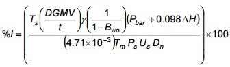
Where:
- %I
- percentage of isokinetic sampling rate
- DGMV
- incremental volume increase on dry gas meter during period t, m3
- t
- incremental sampling period, minutes
- Bwo
- volume proportion of water in stack gas
- ΔH
- orifice pressure differential during period t, cm H2O
- Ts
- absolute stack gas temperature during period t, K
- Dn
- diameter of nozzle opening, cm
- Tm
- absolute temperature at dry gas meter (average of temperatures at inlet and outlet) during period t, K
- Ps
- absolute stack gas pressure, kPa
- Us
- stack gas velocity, m/s (See Part C, Method ON-2, Equation 2-2)
Note: %I is calculated for each set of readings and used to obtain the average %I for the test.
7.0 Discussion of Method ON-5
7.1 Purpose
This method is applied to determine the particulate matter concentration in an enclosed gas stream. A representative sample of stack gas and particulate matter is withdrawn isokinetically from the source using a heated probe, filter, condenser and metering devices.
The particulate matter is collected on an out-of-stack filter (quartz or glass fibre) and in the front half of the sampling apparatus. This method is designed to collect particulates which are greater in size than 0.3 µm at a temperature of 120°C, under ambient atmospheric pressure.
The Source Assessment Specialist needs to be contacted for guidance, if condensable particulate matter is required to be included in the calculation of particulate matter emissions.
7.2 Isokinetic Sampling
An issue, when taking fractions from a gas stream for particle sampling, is to obtain isokinetic sampling. When the velocity through the sample nozzle is equal to the velocity of the surrounding fluid, the sample is said to be taken isokinetically.
The importance of isokinetic sampling depends on the size of the particles, and their density.
If the sample velocity is too slow, sampling is said to be under-isokinetic (see illustration below). The small particles follow the fluid streamlines, which are bent away from the nozzle. The larger particles tend to follow straight lines due to their inertia. This makes them overrepresented in the sample, and the total particle load per gas volume will be higher, than that of the main gas stream.
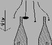
If the sample velocity is too high, sampling is over-isokinetic (see illustration below). The streamlines bend into the nozzle, with the big particles following straight lines due to their inertia. This makes the larger particles underrepresented in the sample, and the particle load per gas volume will be lower than that of the main gas stream.

7.3 Limitations
As noted above, the standard temperature at which particulate is collected by this out- stack method is 120°C. It is assumed that normally particulate matter does not volatilize below that temperature. This temperature is selected so as to be above the boiling point of water yet not so high as to volatilize particulate matter.
It is important to ensure that water does not condense on the filter and cause an excessively high pressure drop. However, there are sources which contain substances which can condense at temperatures above the standard (e.g., acid mist), and thus load the filter. For this reason and others, sources containing significant amounts of such substances may not be able to be sampled using the apparatus and procedure described in this method. Chapter 9.2, Appendix 5B outlines some alternate approaches for use at sources where such conditions exist.
7.3.1 Non-Continuous Sources
Sources which are not in continuous operation, e.g., batch operations, plant shutdowns of short duration, etc., can be sampled with some modifications to the procedure of this method. This is discussed in Chapter 9.3, Appendix 5C.
7.3.2 High Volume Sampling
Positive pressure baghouses and other sources that have low concentrations of particulate matter (less than 5 mg expected catch), low humidity, and non-corrosive gases can be sampled using the High Volume sampling procedure, as outlined in the American Society for Testing and Materials (ASTM) Method D6331-98(2005): Standard Test Method for Determination of Mass Concentration of Particulate Matter from Stationary Sources at Low Concentrations (Manual Gravimetric Method).
7.4 Procedure
The steps of this procedure are separated into several chapters, each chapter of activities being distinct by virtue of its position in the sequence of events and the physical location of the activity. Thus, the preparation procedures are performed in a laboratory. The preliminary survey is usually performed on site a day before the actual testing. The sampling apparatus preparation and sample recovery are done usually in both the laboratory and on site, whereas the analytical procedures are performed in a laboratory at some time after the actual testing.
The procedure is designed so that a representative sample will be obtained from the stack gas; therefore, care must always be taken to ensure that all the components are properly cleaned and that no extraneous matter is picked up in the nozzle or on the filter. Also, the cleanup procedure must be done scrupulously and leak-checks must always be performed to ensure that only stack gas is being sampled.
To ensure that the sample is representative, it must be drawn at an isokinetic rate. This requirement is necessary, because aerodynamic and inertial effects will cause an overestimation of the particulate matter concentration, if sampling sub-isokinetically, or an underestimation for super-isokinetic sampling.
Method ON-5 incorporates the apparatus and procedures of Part E (Method ON-4) and reference should be made to that Part for equations and calculations to determine the moisture content. For each Method ON-5 test run a moisture content analysis and molecular weight analysis (Method ON-3) must be performed.
8.0 Sample Calculations
Sample data for one traverse are recorded in Table 5-1. Normally, a second traverse is done and calculations are based on total sample volume and moisture for both traverses. Respective portions of these data have been used in the sample calculations in Parts C and E (Methods ON-2 and ON-4). Moisture and particulate collection data are recorded in Table 5-2.
From the sample calculations in Parts C and E (Method ON-2 and 4), the following parameters were determined:
Us(avg) = 15.1 m/s
Qs = 30.2 Std m3/s
B(wo) = 0.1708
Assuming that a molecular weight of dry stack gas, Md = 29.66 kg/kg-mole
Ms = 27.67 kg/kg-mole
From Table 5-1 the following data is obtained:
ΔH(avg) = 3.53 cm H2O
Ts(avg) = 510 K
Tm(avg) = 297 K
P(bar) = 100.5 kPa
Vm = 0.983 m3
γ = 0.991
Pm(avg) = P(bar) + 0.098 ΔH(avg)
= 100.5 + (0.098 × 3.53)
= 100.8 kPa
Vm(ref) = (2.94 γ Pm(avg) Vm) ⁄ (Tm(avg))
= (2.94 × 0.991 × 100.8 × 0.983) ⁄ 297
= 0.972 m3
Therefore the volume of the gas sample is 0.972 m3 at 298 K and 101.3 kPa.
Note: In comparing the calculated values of Vm(ref) in this example and in Part E (Method ON-4), there is a slight discrepancy which is explained by the fact that it is permissible to use Pm = Pbar for moisture determination for Method ON-4, whereas for this method Pm must be the true value which is Pbar + 0.098ΔH. However, the slight difference between the two values does not significantly alter the value of Bwo or Ms.
Particulate matter concentration:
Cs = Mp ⁄ Vm(ref)
= 34.7 ⁄ 0.972
= 35.7 mg/STD m3
Particulate matter emission rate:
ERp = (Cs Qs) ⁄ 1000 mg)/g
= (35.7 × 30.21) ⁄ 1000
= 1.08 g/s
Percentage isokinetic sampling rate:
For the first point, first reading:
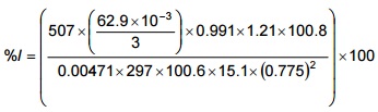
= 100.7%
Listed in Table 5-3 are the calculated velocities and percentage isokinetic for the sample points.
9.0 Appendices to Method ON-5
9.1 Appendix 5A: Determination of Nozzle Size and Setting Isokinetic Sampling Rates
As stated in this method, it is necessary to sample at a rate such that the velocity of the gas entering the sampling nozzle equals the velocity of the undisturbed gas at the sampling point. The ratio of nozzle to stack gas velocity must be 100% ±10%. This ratio is calculated using the stack gas conditions at the time of sampling.
Since some of these conditions, such as moisture content, can only be determined after the test, it is necessary to estimate them as closely as possible for the purposes of choosing the proper nozzle size.
9.1.1 Nozzle Size Determination
A nozzle size must be determined so that it is neither too large, i.e., beyond the ability of the train to draw sample isokinetically at high ΔP's, nor too small, i.e., requiring an impractical small ΔH setting at low ΔP's. The smallest (practical) nozzle is 4.763 mm in diameter.
One method for determining the proper nozzle size is as follows: for true isokineticity,
velocity in nozzle ⁄ velocity in stack = 1
from that:
Equation 5-6
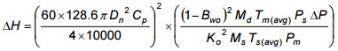
Where:
- ΔH
- orifice pressure differential, cm H2O
- ΔP
- stack gas velocity pressure head, cm H2O
- Dn
- nozzle diameter, cm
- Cp
- Pitot tube coefficient
- Bwo
- moisture content
- Md
- dry stack gas molecular weight, kg/kg-mole
- Ms
- stack gas molecular weight, kg/kg-mole
- Tm(avg)
- average temperature at orifice, K
- Ts(avg)
- average stack gas temperature, K
- Ps
- absolute stack gas pressure, kPa
- Pm
- absolute orifice pressure, kPa
- Ko
- orifice coefficient
These values are estimated or calculated, usually being based on experimental values from a preliminary survey (the nozzle used for that test is picked by approximation). By substituting numerical values for all of the variables of the equation except ΔH, Dn and ΔP, a value for K in the following equation may be determined:
Equation 5-7
ΔH = ΔPKDn4
Having determined K, to obtain the correct nozzle diameter:
- Choose for ΔH the maximum ΔH obtainable or readable from the sampling train.
- Choose for ΔP the maximum ΔP obtained or expected based on the preliminary survey.
- By rearranging the above equation so that:
Dn = [ΔH ⁄ (K ΔP)]¼
and substituting accordingly, Dn may be calculated.
- The nozzle size next smaller to the calculated Dn is the appropriate size.
9.1.2 Isokinetic Sampling Rate Determination
There are several methods used to determine isokinetic sampling rates. One method is as follows:
- if the variables of the above equations are determined at a particular instant the following relationship is found:
Equation 5-9
ΔH = (k' ΔPTm) ⁄ Ts
Where:
k' = (Ts(avg) K Dn4) ⁄ Tm(avg)
- Tm
- instantaneous absolute meter temperature, K
- Ts
- instantaneous absolute stack gas temperature, K
- ΔH
- orifice pressure differential, cm H2O
- ΔP
- stack gas velocity pressure head, cm H2O
- Calculate k'.
- If k'' = k'(Tm ⁄ Ts) by substituting expected values of Tm and Ts, a table of values for k'' may be prepared.
- The above equations simplify to:
Equation 5-10
ΔH = k'' ΔP
Another common method is the use of nomographs, usually commercially prepared. Nomographs are easy to operate and are reasonably accurate. However, most nomographs are pre-set for a pitot coefficient of 0.85 and manufacturers instruction on the use of these nomographs can be modified so that the location of pivot point will correspond to true coefficient; ΔP is multiplied by Cp ⁄ 0.85 and the new ΔP used to set the pivot point. As well, the nomograph must be readjusted during sampling as the meter temperature and stack gas temperature change.
9.2 Appendix 5B: Gas Streams having Significant Concentrations of Substances with Dew Point Greater than 120°C
There is an almost infinite variety of sources and components of gas streams. Some components may have dew points above 120°C, i.e., above the probe and filter heater temperature. The concentration of the component is significant if the component condenses on the filter and this condensate causes such a high pressure drop that the pump is unable to draw at isokinetic rates.
To overcome this problem, the probe and filter must be maintained above the dew point of the component. However, increasing the temperature may volatilize some or all of the particulate matter thus allowing it to pass through the filter to be caught in the impingers. In such cases it may be necessary to install an additional backup filter after the impingers and include the impinger catch and the particulate matter on the backup filter in the calculation of the emission rate.
Another problem possibly encountered with increasing the filter temperature is that reactions may occur on the filter itself which may result in a non-representative particulate matter sample.
The Source Assessment Specialist should be contacted where there is a problem of condensible components so that an appropriate sampling methodology can be agreed upon.
9.3 Appendix 5C: Non-Continuous Sources
Some sources are non-continuous by their nature, e.g., batch processes. As well, some processes slow down or stop at certain times, e.g., lunch break or process interruptions. When this type of problem occurs it is necessary to halt sampling, remove the probe from the gas stream and seal the nozzle tip. Recommence sampling when the process operations return to their usual level.
Since non-continuous processes pose problems with respect to sampling and cannot be generalized, the Source Assessment Specialist should be contacted to discuss the particular situation.
9.4 Appendix 5D: Particulate Matter Sampling in Cyclonic Flow
Particulate matter emission sampling in stacks or ducts with cyclonic flow patterns present significant problems in obtaining representative measurements of concentrations and flow rates. Difficulties also arise in establishing the correct velocity for determining the isokinetic sampling rate.
Cyclonic flow has two angle components identified as the “yaw” and “pitch” angle. The yaw angle is a measure of the degree of tangential flow in the stack. The Ministry uses the yaw angle as the reference to determine if the flow is cyclonic. If the average yaw (based on absolute values) is greater than 15°, the flow is considered cyclonic.
The pitch angle is a measure of the degree of radial flow in the stack. The pitch angle can be visualized as the extent (angle) of stack gas flow towards or away from a person standing (facing) the stack.
A 3-dimensional (3-D) Pitot tube is used to accurately measure the axial stack gas velocity (and volumetric flow rate) in stacks with both yaw angle and pitch angle components. The sampling point determination is done similar to the non-cyclonic sampling point selection approach (equal area method). Refer to US EPA 40 CFR 60 Method 2F for the procedures to determine stack gas velocity and volumetric flow rate with 3-D probes.
For the particulate matter sample collection approach, a null Pitot tube is attached to the typical probe setting used in Method ON-5 trains (Figure 5-1). The face of the null Pitot tube is oriented at right angles to the face of the probe’s S-type Pitot tube. To minimize flow disturbances, the tips of the null Pitot tube are located approximately 5 cm above (downstream) and 10 cm beyond the tips of the probe’s S-type Pitot tube.
This typical probe setting with the null Pitot tube attached measures the yaw angle and, the velocity pressure at that angle, at each point during isokinetic sampling. This approach is suitable only to align the probe nozzle with the obtained yaw angle for collecting the particulate matter sample. The stack gas velocity and flow rate is to be determined using the 3-D Pitot tube.
The position of the nozzle with respect to the yaw angle is determined by rotating the probe/Pitot tube on its axis until the pressure differential across the null Pitot tube is zero. The yaw angle is measured with a protractor with readability of 0.5°. The protractor needs to be solidly fixed to the probe so that when the protractor is reading 0°, the faces of the null Pitot tube are parallel to the axis of the stack or duct.
The rest of the sampling train has the same configuration of the standard Method ON-5 sampling train.
10.0 References
- American Society for Testing and Materials, D6331-98(2005): Standard Test Method for Determination of Mass Concentration of Particulate Matter from Stationary Sources at Low Concentrations (Manual Gravimetric Method), 2005.
- Connor Pacific Environmental Technologies Inc., INCO Super Stack Source Testing Report, Copper Cliff, Ontario, May 2000.
- Environment Canada, Reference Method EPS 1/RM/8, Reference Methods for Source Testing: Measurement of Releases of Particulates from Stationary Sources, December, 1993.
- Ministry of Environment and Energy, Province of Ontario, Source Testing Code, Version 2, Report # ARB-66-80, November 1980.
- United States Environmental Protection Agency, Code of Federal Regulations, Title 40 Part 60, Appendix A, July 1. 1994.
Table 5-1: Field Sampling Report (Example)
Plant*:
Location*:
Date*:
Operators*:
Run No.*:
Pitot Coefficient*: 0.850
Dry Gas Meter (γ) Factor*: 0.991
Initial Leak Check (m3/min):
Final Leak Check (m3/min):
Ambient Temperature (°C): 23
Barometric Pressure (kPa)*: 100.5
Assumed Moisture Content (%):
Static Pressure (mmH2O)*: 10.9
Stack Diameter (m)*: 2.30
Nozzle Diameter (mm): 7.75
Probe Length (m):
Probe Liner:
Gas Stack Molecular Weight (kg/kgmol): 29.66
Schematic of Stack Cross-section
Traverse Number and Direction - 1, N-S
| Sampling Point Number* | Sampling Time (Min.) |
Stack Temp. TS (°C) |
Velocity Head ΔP (mm H2O) |
Orifice Pressure 'Drop ΔH' (cm H2O) |
Dry Gas Meter Reading (Litres) |
Dry Gas Meter Temp. Inlet Tm in (°C) |
Dry Gas Meter Temp. Outlet Tm out (°C) |
Sample Box Temp. (°C) |
Impinger Outlet Temp. (°C) |
Probe Temp. (°C) |
Vacuum mm Hg) |
|---|---|---|---|---|---|---|---|---|---|---|---|
| 1 | 0 | 234 | 1.09 | 3.56 | 000.000 | 19 | 19 | 120 | 18 | 118 | 76 |
| 3 | 236 | 1.09 | 3.56 | 062.90 | 22 | 19 | 120 | 18 | 118 | 76 | |
| 2 | 6 | 236 | 1.09 | 3.56 | 124.90 | 21 | 21 | 120 | 19 | 120 | 76 |
| 9 | 237 | 1.07 | 3.56 | 186.60 | 21 | 21 | 120 | 19 | 117 | 76 | |
| 3 | 12 | 237 | 1.17 | 3.81 | 247.80 | 23 | 22 | 120 | 20 | 125 | 76 |
| 15 | 237 | 1.14 | 3.81 | 312.70 | 24 | 22 | 120 | 19 | 120 | 76 | |
| 4 | 18 | 237 | 1.14 | 3.81 | 377.30 | 24 | 22 | 120 | 19 | 120 | 76 |
| 21 | 237 | 1.19 | 3.81 | 441.90 | 25 | 23 | 120 | 18 | 119 | 76 | |
| 5 | 24 | 237 | 1.02 | 3.05 | 506.50 | 27 | 23 | 120 | 19 | 120 | 76 |
| 27 | 238 | 1.02 | 3.30 | 564.60 | 27 | 24 | 120 | 20 | 118 | 76 | |
| 6 | 30 | 238 | 1.02 | 3.56 | 623.80 | 28 | 24 | 120 | 19 | 119 | 89 |
| 33 | 238 | 1.02 | 3.56 | 685.00 | 28 | 25 | 120 | 19 | 117 | 89 | |
| 7 | 36 | 238 | 1.02 | 3.56 | 745.90 | 28 | 26 | 120 | 20 | 120 | 89 |
| 39 | 238 | 0.99 | 3.43 | 806.80 | 29 | 27 | 120 | 19 | 121 | 89 | |
| 8 | 42 | 238 | 0.94 | 3.30 | 867.10 | 29 | 28 | 120 | 18 | 120 | 89 |
| 45 | 237 | 0.97 | 3.30 | 925.20 | 29 | 28 | 120 | 18 | 122 | 89 | |
| 48 | 983.50 | ||||||||||
| avg. 237 | avg. 1.06 | avg. 3.53 | avg. 26 | avg. 23 |
| Final wt. (mg) | Tare wt. (mg) | Particulate wt. (mg) | |
|---|---|---|---|
| (a) Filter | 756.3 | 738.1 | 18.2 |
| (b) Beaker containing washing from nozzle, probe, cyclone (if used) and front half of filter holder | 104709.7 | 104693.2 | 16.5 |
| (c) Cyclone collection flask | n/a | n/a | n/a |
| (d) Beaker containing impinger contents and washing from impingers and back half of filter holder | 101385.0 | 101368.2 | 16.8 |
| Weighing room relative humidity: | pre-test = 42% post-test = 39% |
|---|---|
| total wt. of particulate (excluding impinger contents) | 34.7 mg |
| Final wt. (g) | Tare wt. (g) | wt. of H2O (g) | |
|---|---|---|---|
| Impinger #1: | 828.4 | 696.3 | 132.1 |
| Impinger #2: | 447.0 | 436.2 | 10.8 |
| Impinger #3: | 417.7 | 417.5 | 0.2 |
| Impinger #4: | 685.7 | 681.6 | 4.1 |
| Desiccant saturation level | < ¼ |
|---|---|
| total wt. of H2O | 147.2 g |
| Sampling Point Number | Velocity (m/s) | % Isokinetic |
|---|---|---|
| 1 | 15.3 | 100.8 |
| 15.3 | 99.2 | |
| 2 | 15.3 | 98.8 |
| 15.1 | 99.0 | |
| 3 | 15.8 | 100.3 |
| 15.7 | 100.9 | |
| 4 | 5.7 | 100.9 |
| 16.0 | 98.8 | |
| 5 | 14.8 | 96.2 |
| 14.8 | 98.1 | |
| 6 | 14.8 | 101.3 |
| 14.8 | 100.8 | |
| 7 | 14.8 | 100.8 |
| 14.6 | 101.2 | |
| 8 | 14.2 | 100.0 |
| 14.4 | 99.2 | |
| Average | 15.1 | 99.8 |
Figure 5-1: Particulate Matter Sampling Train
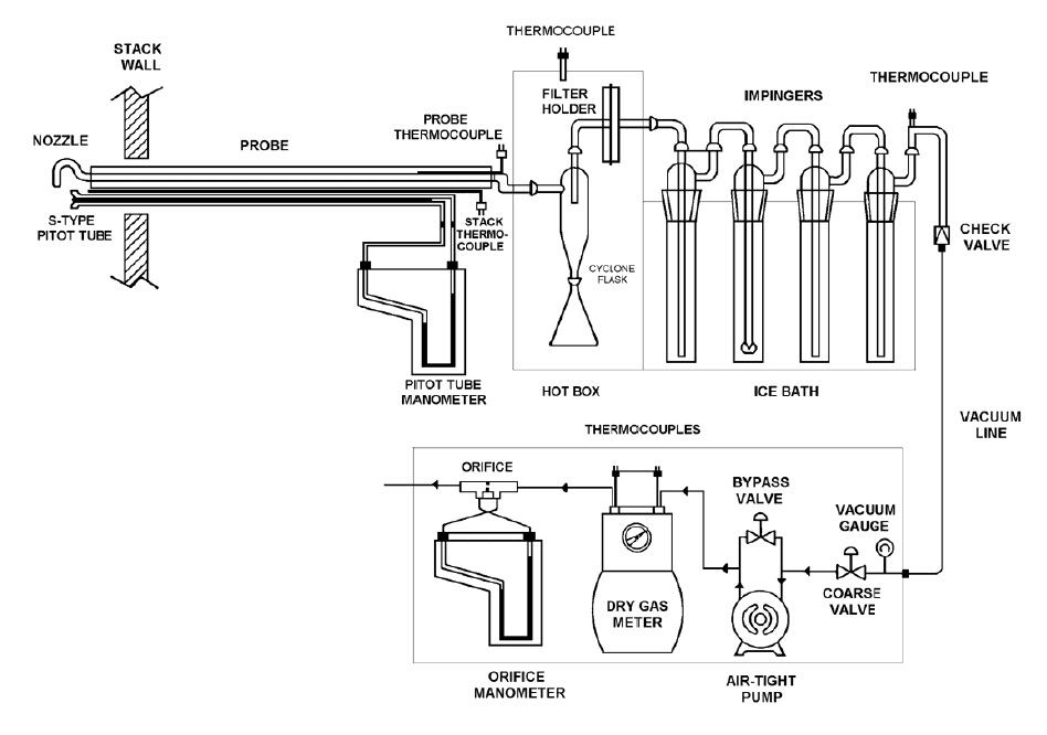
There is a long rectangular probe with an s-type pitot tube and a nozzle attached at the end, located inside the stack wall. The probe extends from inside the stack wall to the right where it is attached to a hot box. Just before the hot box, there is a probe thermocouple and a stack thermocouple. The pitot tube lines extend the length of the probe and are connected to the two ends of the pitot tube manometer.
Inside the hot box is a cyclone flask, filter holder and thermocouple.
The outside of the hot box has the outlet of the filter holder connected to an impinger by specialized glassware. There are four impingers connected in series by u-tubes. All impingers are inside an ice bath. The final impinger outlet is connected to a thermocouple and a vacuum line down to a vacuum gauge.
The vacuum gauge has a fine valve and a coarse valve and is connected to an air tight pump with a bypass valve. The bypass valve is connected to a dry gas meter that has two thermocouples on the inlet and outlet. The dry gas meter is connected to an orifice with an orifice manometer.