Part G - Method ON-6: Determination of Odour Emissions from Stationary Sources
Part G: Method ON-6: Determination of Odour Emissions from Stationary Sources
1.0 Introduction
This chapter outlines three traditional methods of sampling for odours (dynamic pre-dilution, evacuated lung and flux chamber methods) and one modified method specific to sampling open bed biofilters. Assessors must choose the most appropriate sampling method based on a preliminary assessment of each individual source. Certain source parameters may dictate that a non-traditional method may be required to ensure accurate, representative data. Several non-traditional methods that have been successfully applied in the past are outlined in the appendix of this chapter. When developing and/or using a non-traditional method, it is necessary that the Source Assessment Specialist be contacted to discuss sampling strategies.
Methods for quantifying fugitive odour concentrations and emission rates have not been outlined in this document. Fugitive odours can be a major contributor to a facility’s aggregate odour impact; as such, these emissions are required to be addressed. The unique nature of facilities and the way in which fugitive odours may be emitted requires that the sampling strategy for sampling fugitive odour emissions be dealt with on an individual basis.
2.0 Purpose
This method is intended to determine the odour concentration and emission rate of undefined mixtures of gaseous odorants of a gas stream in a stack, duct and area source. The samples are collected by dynamic dilution with neutral gas, undiluted by evacuated lung, or via flux chamber sampling procedures and are evaluated using dynamic olfactometry with a panel of human assessors (odour panel evaluation technique).
3.0 Limitations
The methodology outlined within this chapter is not applicable to measuring odours from solid odour emitting particles or droplets of odorous fluids within a “supersaturated” gas stream. The Source Assessment Specialist should be contact to discuss sample strategies when it is deemed that a customized (non-traditional) sampling strategy is necessary.
4.0 Definitions
Listed in this chapter are the more frequently referenced definitions. For a complete list of definitions, refer to the European Standard EN13725: 2003 Determination of Odour Concentration by Dynamic Olfactometry or its most recent version.
- Detection threshold (Sample)
- Dilution factor at which the sample has a 50% probability of being detected by a human assessor.
- Dilution factor
- The ratio between sample flow or volume after dilution (Total Sample Volume) and the flow or volume of the odorous gas (“Undiluted” Sample Volume).
- Dynamic dilution
- Dilution achieved by mixing two known flows of gas; odorous sample and neutral gas, respectively. The rate of dilution is calculated from the flow rates.
- Field Blank
- odourless air sample collected at the sampling site, treated as a sample in all respects, including contact with the sampling devices and exposure to sampling site conditions, storage, preservation, and all analytical procedures.
- Flux Chamber
- A device used to isolate a surface area for collecting gaseous emissions being generated as neutral gas is being passed over the enclosed area.
- Maximum dilution factor
- Maximum achievable dilution factor of the olfactometer; an instrument property.
- Minimum dilution factor
- Minimum achievable dilution factor of the olfactometer; an instrument property.
- Neutral gas (diluent)
- Air or nitrogen that is treated in such a way that it is as odourless as technically possible (nitrogen of 4.8 Grade or higher is recommended) and that does, according to panel members, not interfere with the odour under investigation.
safety warning: Nitrogen is only used to predilute the sample itself. For the olfactometer, the neutral gas which is used to dilute the sample and present a reference shall be air.
- Odour emission rate
- The quantity of odour units (ou) which crosses a given surface divided by time. It is the product of the odour concentration Cod, and the wet reference volumetric flow rate (at standard temperature and standard atmospheric pressure, 298 K and 101.3 kPa respectively). It is typically expressed as ou/s.
- Odour concentration
- Number of odour units per volume of gas at wet standard conditions. It is typically expressed as ou (m3 basis).
- Odour unit (O.U. Dimensionless)
- Number of unit volumes of odourless gas required to dilute one unit volume of odorous gas (under standard conditions) to reach the odour panels detection threshold. The accepted reference value is equivalent to 123 µg n-butanol (CAS 71-36-3). Evaporated in 1 cubic metre of neutral gas (at standard conditions) this produces a concentration of 0.040 µmol/mol.
- Odour Panel
- Composed of 8 assessors who are qualified to judge samples of odorous gas using dynamic olfactometry. Each assessor must be appropriately screened and meet the selection criteria outlined in the EN 13725:2003 standard.
- Pre-Dilution
- Drawing a sample of stack gas while simultaneously diluting it with neutral gas for the purpose of preventing condensation and/or sorption of odours upon sample collection and to reduce sample gas temperature.
- Sample
- The amount of gas which is assumed to be representative of the gas mass or gas flow under investigation and which is examined for odour concentration.
- Standard Conditions for Olfactometry
- Room temperature (298K) and normal atmospheric pressure on a wet basis.
- Sweep gas
- Neutral gas which is introduced at a low velocity into a flux chamber.
5.0 Dynamic Pre-Dilution Sampling
Source parameters may result in the necessity to “pre-dilute” a sample prior to collection in a sample container. In all cases pre-dilution of stack gas is required if:
- It is determined that the stack gas temperature may degrade the sample container;
- The moisture content of the stack gas will result in condensation forming in the sample container;
- It is determined that the odour intensity is great enough that it results in a positive response at the highest dilution factor of the olfactometer.
5.1 Apparatus
The odour sample collection system must be capable of dynamically pre-diluting the stack gas with odour free purified nitrogen. The quantity of nitrogen shall be sufficient to prevent condensation and sorption of odours upon sample collection and cooling to ambient temperatures.
A sketch of an acceptable dynamic pre-dilution odour sample collection system is shown in Figure 6-1a. Other odour sample collection systems may be used, provided it can be demonstrated that they are effective in preventing condensation upon sample collection and cooling to ambient temperature.
- Probe – structurally stable stainless steel, Teflon®, borosilicate or quartz glass. The distance between the probe and the sample container shall be kept to a minimum.
- Velocity & Flow Measurement Device – with a resolution of 0.01 m/s such as an anemometer or pitot-tube; reference should be made to Method ON-2 concerning pitot tube configuration and calibration.
- Temperature Sensor – thermocouple or other calibrated device capable of measuring stack gas temperature with a maximum acceptable error of 1.5%. The sensor must be checked according to the procedure outlined in Method ON-2 (Chapter 7.5, Appendix 2E).
- Differential Pressure Gauges – to use with Pitot tube and orifice meter. Inclined manometer or devices of equivalent sensitivity, readable to the nearest 0.10 mm water column for differential pressure (ΔP) values between 0.10 mm and 25 mm WC, and readable to the nearest 1.3 mm WC for ΔP values greater than 25 mm WC; a more sensitive unit will be required if a ΔP reading is found to be less than 5 smallest scale divisions, see Method ON-2 (Chapter 7.3, Appendix 2C).
- Sample Line – made of Teflon®, stainless steel or glass; the distance between the probe and the sample container shall be kept to a minimum. All fittings shall be clean and odour free and preferably of Telfon® or stainless steel composition.
- Sample Containers – material of construction shall be Tedlar®, Teflon® or any other materials (such as Nalophan®) which will not compromise the integrity of the sample. When such other materials are proposed, approval from the Source Assessment Specialist is required. The sample container shall be of sufficient volume to carry out a minimum of an eight member odour panel evaluation.
- Heated Sample Box – a heated enclosure (or heated probe assembly) shall be used to maintain the temperature of the stack gas, up to a maximum temperature of 120°C, from the point at which it is drawn from the stack, to the point when it has been diluted with pre-purified nitrogen. Maintaining the sample gas stream at the stack temperature prevents the formation of condensation within the sample apparatus prior to the point of dilution.
- Valves – capable of metering the dilution air flow and the sample flow; material of construction shall be Teflon®, glass or stainless steel.
- Orifice Meters – capable of accurately measuring the flow ranges required for pre-dilution flow, sample flow and total flow. The material of construction shall be glass, Teflon® or stainless steel.
- Pre-Dilution Odourless Gas – nitrogen (4.8 grade or higher).
5.2 Preparation
- The Pitot tube and orifice meters must be maintained in accordance with the standard accepted procedures and calibrated prior to testing, in accordance with Method ON-2 (Chapter 7.1, Appendix 2A) and Method ON-4 (Chapter 6.2, Appendix 4B). The orifices shall be calibrated in the flow ranges required for the tests.
- The probe and the sample transfer line must be clean and free of residual odour. If any contamination is observed on the sample transfer line, the sample transfer line must be replaced. A new and/or clean odour free sample line should be used for each source being measured.
- The sample containers are required to be preconditioned by heating to 70°C (158°F) and flushed continuously with odourless air for a minimum of 8 hours. All containers should be checked for residual odours prior to use. Note that materials other than Tedlar® and Telfon® may not require such preconditioning. However, guidance in this issue is required from the Source Assessment Specialist.
- The sampling site or location should be selected where odours are expected to be uniform, well mixed and in gaseous form, but note that the flow measurements need to be conducted at a location that meets the minimum requirements listed in Method ON-1.
- The odour collection system must be calibrated for its complete range of pre- dilution ratios, across the units’ range of operating temperatures, using a tracer gas and a flame ionization detector (FID). This calibration shall be completed at a minimum frequency of 6 months (see Hydrocarbon Calibration procedure in Chapter 10.1, Appendix 6A). Prior to utilizing equipment in the field, complete flow checks on each sample collection system and compare the results to data collected during most recent tracer gas calibration. Anomalies shall be flagged and the system shelved until it is recalibrated.
All calibration data must be available on request prior to or during the actual testing, and must be submitted with the final report.
- The odour sampling collection system must be leak-checked prior to mobilization to ensure sample integrity and is performed according to the following procedure:
Odour Sampling Leak-Check
- Plug both the inlet to the probe and the dilution gas inlet.
- Using a metering system comprised of a vacuum gauge, leak-free pump, and a calibrated dry gas meter (or calibrated pump) draw a vacuum of 380 mm Hg.
- Maintain the vacuum for at least 1 minute. A leakage rate of 4% of the undiluted sample flow or greater is unacceptable and if found, the sampling train should be dismantled and reassembled until the leak is adequately reduced or eliminated.
5.3 Volumetric Flow Rate Determination
Volumetric flow rate must be determined in accordance with Method ON-2. Molecular weight and stack gas moisture determination should be completed following Method ON-3 and ON-4 respectively.
The exhaust gas stream should be checked for stratification. Please see the chapter titled “Stratification Test Procedure” in Environment Canada’s Report EPS 1/PG/7, December 2005 (or the most recent version) if further guidance is required.
If stack gas stratification is identified, contact the Source Assessment Specialist to discuss the most appropriate strategy for sample collection.
5.4 Pre-Dilution Ratio Determination
The odour sample is “pre-diluted” with odourless gas (nitrogen) during sampling to prevent condensation and absorption of odours upon sample collection and transport; therefore, preliminary tests must be carried out at the source(s) to determine the required pre-dilution ratio.
When an odour sample is collected from a source that exhausts gas containing water vapour, there is the potential for this water vapour to condense. The condensed water, called dew has the potential to absorb odorous compounds in the sample gas and negatively bias the odour analysis results.
The sample “dew point” is the temperature at which the gaseous sample becomes saturated with water vapour. If the sample temperature is maintained at a level higher than the dew point temperature, water vapour remains gaseous. If the sample cools to a temperature below the dew point, water vapor will condense and the odour sample is deemed invalid. Pre-diluting the gas sample with dry nitrogen will lower the total moisture content in the sample container, therefore lowering the dew point temperature. This procedure is used to avoid the formation of condensation which can occur as the sample gas cools after being extracted from the exhausts gas stream.
The following procedure defines the method for calculating the pre-dilution ratio (dry nitrogen to stack gas) necessary to prevent the formation of condensation in a sample container and is based on the measured stack gas moisture content and the lowest temperature at which the gaseous sample is expected to reach during transport and analysis.
5.4.1 Procedure for Calculation of the Pre-Dilution Ratio
- Determine the stack gas moisture content following the procedures outlined in Part E, Method ON-4. Record the sample volume (m3 of dry exhaust gas) and total condensed moisture collected (mL or g) and calculate the moisture content in g/m3.
- Determine the lowest temperature that the sample gas will reach during transport and/or analysis (i.e., ambient temperature or the odour evaluation laboratory temperature), and record the temperature of the exhaust gas.
- From Table 6-1 obtain the amount of water in air (g/m3), assuming 100% relative humidity, for the ambient temperature or the expected temperature of the odour evaluation laboratory; which ever is lower.
- If the total condensed moisture per cubic metre obtained in Step 1 (g/m3) exceeds that obtained in Step 3 (g/m3) sample pre-dilution is required.
Note: For supersaturated gas streams, it is necessary to use the actual water condensate volume collected;
- To determine the optimum pre-dilution ratio, divide the measured stack gas moisture content (g/m3) from Step 1 by the amount of water in air at the dew point temperature selected in Step 3.
For example, if the stack gas moisture content is measured to be 45 g/m3 and the lowest temperature the sample will reach is assumed to be that of the ambient temperature of 18°C; based on Table 6-1 the stack gas sample must be diluted to contain a maximum of 15.4 g of water per cubic metre of air to prevent condensation. By dividing the stack gas moisture condensate of 45 g/m3 by the water content at the selected dew point temperature (15.4 g/m3), the dilution ratio required to prevent condensation is estimated at 3 volumes of nitrogen by 1 volume of exhaust gas sample.
- The pre-dilution ratio used in the field should be a maximum of 20% or 10 dilution factors higher than that calculated based on this methodology. A dilution level lower than that calculated shall not be used, as it is likely to result in the formation of condensation. Sample teams should strive to use dilution factors as close as possible to the calculated optimum pre-dilution ratio.
- In cases when the odour concentration is high enough to elicit a positive response from panelists when the olfactometer is diluting the odour sample in its upper dilution range, the odour assessment results are rejected as inconclusive. A new set of samples need to be collected, making sure that a suitable pre- dilution ratio is selected that will accommodate the minimum number of dilution step presentations required by the odour evaluation facility. Preliminary source assessment data may be presented in the pre-test plan for prior approval from the Source Assessment Specialist to increase the dilution ratio beyond the pre- dilution ratio limits outlined above.
5.4.2 Alternate Methods for the Determination of the Optimum Pre-Dilution Rates
The following procedures may be used to determine the dew point of odour samples for the purposes of setting pre-dilution rates. They can be used in lieu of Method ON-4’s moisture determination, if stack gas temperature is less than 100°C, and the gas stream does not contain water droplets. Deviation from the 100°C criteria may be considered acceptable however pre-consultation with the Source Assessment Specialist is necessary.
5.4.2.1 Relative Humidity
The relative humidity is the ratio of the actual water vapour pressure to the saturation water vapour pressure (100% humidity) at a selected temperature. Using a commercially available electronic sensor relative humidity can be easily measured.
In order to use relative humidity measurements for pre-dilution ratio determination, the following steps are required:
- Using an electronic sensor measure the relative humidity of the stack gas (following the manufacturer’s instructions).
- Measure the stack gas temperature; Ts (refer to Method ON-2).
- Obtain the amount of water in air (g/m3), assuming 100% relative humidity, at the stack gas temperature.
- Multiply the water in air value (obtained from Step 3) by the percent relative humidity (obtained from Step 1). This will determine the stack gas moisture content (g/m3).
- From Table 6-1 obtain the amount of water in air (g/m3), assuming 100% relative humidity, for the ambient temperature or the expected temperature of the odour evaluation laboratory; which ever is lower.
- If the total condensed moisture per cubic metre obtained in Step 4 (g/m3) exceeds that obtained in Step 5 (g/m3) sample pre-dilution is required.
- Follow Steps 5 to 7 of the pre-dilution determination procedure (Chapter 5.4.1) to calculate the required dilution rate.
5.4.2.2 Psychrometer (Wet and Dry Bulb Thermometer)
Wet and dry bulb thermometer technique can be used if:
- stack gas temperature greater than 0°C and less than 100°C;
- the gas stream velocity is greater than 5 m/s; and
- the gas stream does not contain water droplets or acid mist.
In order to use the wet and dry bulb thermometer technique, for pre-dilution determination, the following steps are required:
- Measure the dry stack gas temperature (refer to Method ON-2).
- Simultaneously measure the wet bulb stack gas temperature.
- Based on the stack gas wet and dry bulb temperatures, use a psychrometric chart to determine the volume of water vapour in the stack gas.
- From Table 6-1 obtain the volume of water in air (g/m3), assuming 100% relative humidity, for the ambient temperature or the expected temperature of the odour evaluation laboratory; whichever is lower.
- If the total condensed moisture per cubic metre obtained in Step 3 (g/m3) exceeds that obtained in Step 4 (g/m3) sample pre-dilution is required.
- Follow Steps 5 to 7 of the pre-dilution determination procedure (Chapter 5.4.1) to calculate the required dilution rate.
The results of the pre-dilution ratio determination must be made available upon request during collection of the “optimum dilution” ratio samples and shall be included in the final report.
If uncertain on what approach to use to determine the “optimum dilution” ratio, the Ministry’s Source Assessment Specialists need to be contacted for guidance.
5.5 Sampling Procedure (Non-Stratified Gas Stream)
- Assemble the odour sample collection system. Place the probe at a single point near the centre of the stack or duct. If the stack or duct exceeds 2.0 min diameter, the sample probe can be placed at any single point, greater than 1.0 maway from the stack or duct wall.
- Ensure that all sample ports, including the area around the sample probe, are covered to prevent the dilution of the gas stream.
- Heat the front end of the sample apparatus (between the stack and the point of dilution) to the temperature of the stack gas, or 120°C whichever is lower. To prevent the formation of condensation in the sample line prior to the stack gas being diluted with nitrogen, the sample apparatus must be heated to a temperature equal to or no more than 20% higher than the measured stack temperature; not to exceed 120°C.
- To condition the sample container, start the flow of nitrogen and adjust the stack gas sample flow rate to obtain the proper predetermined pre-dilution ratio. Fill the sample container with the pre-diluted stack gas, and then empty the sample container. Repeat the procedure. The sample container is now conditioned for the collection of an odour sample.
- Adjust the sample flow rate such that the sample container is filled over a 10 minute sampling period. Connect the sample container, obtain sample and record all data according to Table 6-2.
- The operator must watch over the sampling trains flow/pressure measuring device(s) throughout the entire test period to ensure a consistent pre-dilution rate is being achieved for the duration of the test.
- A minimum of three separate samples shall be collected from each source at the optimum dilution rate.
5.6 Sample Recovery
After completion of the ten (10) minute sample collection, the sample container is immediately sealed, labelled and shielded from direct sunlight. To protect from photo- chemical degradation samples shall be placed in an opaque container for storage and transport.
Samples shall be analyzed within 24 hours of sample collection by an odour analysis laboratory that is acceptable to the Source Assessment Specialist.
Note: Caution should be taken when using stickers, tapes or other adhesive/solvent based products to label sample containers as there is the potential for odours to migrate into the sample container.
6.0 Undiluted – Evacuated Lung Sampling Procedure
In the case that stack temperatures and moisture content are low and if it is determined that the stack gas odour concentration is within the dilution range of the olfactometer, the evacuated lung sampling procedure may be utilized.
6.1 Apparatus
The odour sample collection system must be capable of drawing a sample at a steady sampling rate spanning a 10 minute sample period. A pump is used to evacuate a rigid leak-free vessel creating negative pressure which draws a sample of stack gas from the gas stream, through a sample probe, into a sample bag contained within the vessel.
A sketch of an acceptable evacuated lung odour sample collection system is shown in Figure 6-1b. Other odour sample collection systems may be used, provided it can be demonstrated that they are effective in obtaining a sample with minimal possibility of contamination.
- See Chapter 5.1 (a to f).
- Sample Lung – rigid vessel or container, capable of maintaining a vacuum sufficient to pull the sample from the exhaust stream, within the time required.
- Pump – Leak free diaphragm-type pump (with adjustable flow) or equivalent, which is capable of delivering at least 1 litre/minute under a steady sampling rate lasting 10 minutes.
Note: When sampling a stack or duct with significant negative pressure, a pump with a higher capability will be required.
- Flow meter - 0 to 5 litre flow range
6.2 Preparation
See Chapter 5.2 (Steps 1 to 4).
6.3 Volumetric Flow Rate Determination
See Chapter 5.3.
6.4 Sample Procedure
- Assemble the odour sample collection system. Place the probe at a single point near the centre of the stack or duct. If the stack or duct exceeds 2.0 min diameter, the sample probe can be placed at any single point, greater than 1.0 maway from the stack or duct wall.
- Ensure that all sample ports, including the area around the sample probe, are covered to prevent the dilution of the gas stream.
- To condition the sample container, connect the sample container to the sample line, seal the rigid vessel and start the pump. Fill the sample container with the stack gas. Empty the sample container and repeat the above procedure. The sample container is now conditioned for the collection of odour samples.
- Reconnect the conditioned sample container, seal the rigid vessel and begin sampling by starting the pump; adjusting the sample flow rate such that the sample container is filled over a 10 minute sampling period. Record all data according to Table 6-2.
- If sampling a gas stream of negative static pressure, it is important to disconnect and seal the sample container immediately following sample collection to ensure the sample is not drawn back into the stack or duct. When sampling a stack or duct with a high negative pressure it may be necessary to incorporate a clean odour free stainless steel needle valve between the sample probe and sample container. This valve can be closed immediately following sample collection to prevent sample loss.
- A minimum of three separate samples shall be collected from each source.
6.5 Sample Recovery
See Chapter 5.6.
7.0 Area Source – Flux Chamber Sampling Procedure
This method is applicable to sampling for odours from area sources with no induced flow, including but not limited to: waste water lagoons, sewage treatment settling tanks/clarifiers, landfills and compost piles. This method is not applicable to open bed biofilters.
Area sources are rarely homogeneous in nature. As a result, it is important that a well developed sampling strategy is employed to ensure that the samples collected provide a fair representation of the odour emission potential of the source as a whole. This may require sampling to be completed at multiple locations, for each individual source.
A sketch of an acceptable area source odour sample collection system is shown in Figure 6-1c. Other odour sample collection systems and procedures may be used, provided it can be demonstrated that they are suitable for their intended purpose and have been approved by a Source Assessment Specialist.
Note that sampling using this approach is not to be conducted on rainy days (or when rain occurs within 24 hours prior to the scheduled sampling); as the rain will interfere with the normal generation and release of the odorous emissions (odour scrubbing effect).
7.1 Apparatus
- Sample Line – made of Teflon®, or glass; the distance between the probe and the sample container shall be kept to a minimum. All fittings shall be clean and odour free and preferably of Telfon® or stainless steel composition.
- Sample Containers – material of construction shall be Tedlar®, Teflon® or any other materials (such as Nalophan®) which will not compromise the integrity of the sample. When such other materials are proposed, approval from the Source Assessment Specialist is required. The sample container shall be of sufficient volume to carry out a minimum of an eight member odour panel evaluation.
- Sample Lung – rigid vessel or container, capable of maintaining a vacuum sufficient to pull the sample from the exhaust stream, within the time required.
- Pump – Leak free Teflon® coated diaphragm-type pump (with adjustable flow) or equivalent, which is capable of delivering at least 1 litre/minute under a steady sampling rate lasting 10 minutes.
- Flow meter – Two (2) flow meters with a 0 to 5 litre flow range.
- Odourless Gas – Nitrogen (4.8 grade or higher).
- Flux Chamber – Enclosure with a cylindrical shaped base and a spherical top, constructed of stainless steel or plexiglass. The unit shall be equipped with odour free fittings which will allow for the introduction of neutral (sweep) gas, the extraction of a gaseous sample and the relief of sweep gas pressure (i.e., with a bleed valve). See Figure 6-2 for a diagram. The flux chamber may be equipped with a floatation device for sampling liquid surfaces.
7.2 Preparation
- The sample containers are required to be preconditioned by heating to 70°C (158°F) and flushed continuously with odourless air for a minimum of 8 hours. All containers should be checked for residual odours prior to use. Note that materials other than Tedlar® and Telfon® may not require such preconditioning. However, guidance in this issue is required from the Source Assessment Specialist.
- The flux chamber shall be clean and free of residual odour prior to each use.
- The sample transfer line must be clean and free of residual odour. If any contamination is observed on the sample transfer line, the sample transfer line must be replaced. A new and/or clean odour free sample line should be used for each source being measured.
7.3 Sample Procedure
- Assemble the odour sample collection system and place the flux chamber over the surface area to be tested. Ensure that the cylindrical walls of the flux chamber are slightly below the sampling surface thereby preventing the introduction of ambient air into the chamber.
- Start the flow of metered sweep gas into the flux chamber. The flow rate shall be metered at 0.00064 m3/s based on one square metre of coverage. Using an EPA style flux chamber with a diameter of 40.6 cm and area coverage of 0.13 m2, sweep gas flow rates shall be metered at 5 L/min.
Flux chambers covering a larger surface area will require a higher sweep gas flow rate. In such cases, the sweep gas flow rate results will need to be normalized to 0.00064 m3/s based on one square metre of coverage.
- Allow a minimum of 4 air exchanges to occur within the chamber prior to drawing a sample. Each air exchange represents passing a volume of sweep gas into the flux chamber that is equal to the chamber volume.
- To condition the sample container, connect it to the sample line within the rigid vessel. Seal the vessel and start the pump. Fill the sample container and stop the pump. Empty the sample container and repeat the above procedure. The sample container is now conditioned for the collection of odour samples.
- Reconnect the conditioned sample container to the sample line within the rigid vessel, seal the vessel and begin sampling by starting the pump. The sample flow rate is required to be such that the sample container is filled over a 10 minute sampling period. The sweep gas volumetric flow rate must exceed that of the sample flow rate. Record all data according to Table 6-3.
- A minimum of three separate samples shall be collected from each source; but as indicated previously, area sources are rarely homogeneous in nature. The number of separate samples may be higher than three; depending on the number of selected locations that will provide a fair representation of the odour emission potential, of the source as a whole.
Note that when using the flux chamber approach, for collecting odour samples, the odour flux (ou/s/m2) is calculated based on the sweep gas rate. See Equations 6-3 and 6-4.
The flux chamber sweep gas flow rate and its normalization are used for convenience to standardize the sampling strategy and emission rate calculations. In actuality the rate of odorant release from a surface area will depend upon many parameters, some of which include: temperature and porosity of the surface, ambient temperature and relative humidity, substance chemical and physical composition, surface tension between the odorant and the surface area as well as the sweeping effect of the wind on the surface area. The flux chamber sampling method is being adopted to assist in standardizing sampling strategies and providing repeatable results.
7.4 Sample Recovery
See Chapter 5.6.
8.0 Open Bed Biofilter Sampling Method
Open bed biofilters have characteristically low air flow velocities over a large surface area. It is this induced air flow that makes sampling using area source odour sampling methods (i.e flux chamber sampling) unsuitable. If used, a flux chamber would trap air exiting the biofilter and build positive pressure within the chamber. This positive pressure at the surface of the biofilter would disturb the natural flow of the unit diverting air around the chamber in the path of least resistance. This would in-turn result in an inaccurate, non-representative odour samples.
This sample method utilizes a passive sampling hood designed to produce minimal resistance to the biofilters natural air flow, while funnelling the gas stream through a diameter of ducting small enough to produce measureable flow rates. An evacuated lung sampling apparatus is used in conjunction with the sampling hood to draw odour samples from its exhaust duct.
A sketch of an acceptable open bed biofilter odour sample collection system is shown in Figure 6-1d. Other odour sample collection systems and procedures may be used, provided it can be demonstrated that they are suitable for their intended purpose and have been approved by a Source Assessment Specialist.
8.1 Apparatus
A well designed sampling hood is essential to the success of this procedure. The following three items need to be considered when constructing the sample hood:
- The size of the capture hood and diameter of its exhaust duct needs to be sufficient to provide measureable velocity readings.
- The angle of the capture hood (inverted funnel) must provide minimal resistance to the natural flow of the biofilter exhaust.
- The entry angle from the capture hood to the exhaust duct needs to be designed to provide a smooth transition, minimizing the possibility of positive pressure build-up in the capture hood.
It is imperative that the sample hood is designed to minimize the loss of gas stream velocity and prevent the build-up of pressure as the biofilter emissions pass through the apparatus. A high positive pressure within the sampling hood (created by a poorly designed sampling apparatus) has the potential to alter the natural air flow of the bed; providing inaccurate non-representative sampling results. Pressure build-up within the sample hood, resulting in entry losses, will vary depending on the angle of the capture hood in relation to the biofilter bed. It is recommended that a hood height to base diameter ratio of 3 to 1 be used.
In addition to limiting losses due to the potential pressures and disturbances between the biofilter bed, capture hood and exhaust duct, the duct should be designed to allow gas velocity readings of 0.2 m/s or higher. Velocity readings can typically be measured accurately at levels as low as 0.2 m/s by commercially available air velocity meters.
8.2 Sampling
Odour sampling locations are established by conducting an initial airflow survey over the surface area being assessed. This survey should be completed by obtaining flow measurements using twelve (12) or more equal area quadrants. This survey will reveal any airflow trends; preferential air flow, possible breakthrough zones, dead spots or relative uniformity across the bed.
If the biofilter displays relative uniformity across the bed (considered to be less than 20% variance from the average measured velocity) sampling should be completed at a minimum of three separate locations across the bed.
If there is significant variance in measured velocity (> ±20%), sampling zones need to be established. These zones are based on quadrants with similar flow characteristics. The number of sampling zones defined will be subject to the amount of flow variation and the flow patterns observed. A minimum of three odour samples should be collected from each of the defined zones.
Odour samples and temperature/flow measurements are taken from the straight vertical section of duct extending above the capture hood (see figure 6-1d for a sketch of the apparatus). An evacuated lung sampling system is used to draw the odour sample into the sample container (see Chapter 6). A pre-dilution sampler may be needed if high moisture levels and/or very high odour concentrations are encountered (see Chapter 5).
The resultant odour concentration is assigned to each quadrant within the defined sample zone. The product of the zones average velocity (calculated to reflect that of the bed surface), total area and the resulting odour concentration provides the odour emission rate. Emission rates for biofilters are typically entered into the air dispersion model as a point source. If there is significant variation in the biofilter velocity profile and numerous sample zones are identified, it may be necessary to model the biofilter as more than one point source – utilizing a diameter of equal area – and assigning relative emission rates and flow characteristics.
If the velocity profile of the biofilter is relatively uniform an inlet flow measurement is preferred for calculating volumetric flow rates and surface velocity, as it is likely to be more accurate. If this method is employed it is necessary to adjust the flow rate to reflect the temperature and moisture characteristics of the gas flow as it exits the biofilter (typically at saturation).
Note that sampling using this approach is not to be conducted on rainy days (or when rain occurs within 24 hours of the scheduled sampling); as the rain will interfere with the normal generation and release of the odorous emissions (odour scrubbing effect).
9.0 Field Blanks
Field blanks are required to be collected immediately prior to commencing source sampling. A minimum of one field blank is required for each test date.
Field blank samples are collected to determine the existence and magnitude of contamination problems and to assess the level of quantification of the sampling system and analytical procedure.
Blanks reflect the amount of contamination introduced into the odour samples during sample collection, transfer or analysis. They are used to determine whether (1) equipment-cleaning protocols adequately remove residual/background contamination from the sampling trains and containers, (2) equipment handling and transport periods introduce contamination, and (3) sampling, transport and sample-processing procedures result in contamination.
The procedure for obtaining a field blank requires that the blank be exposed to the same environmental conditions as all other odour samples. The basic steps for the collection of a field blank follow:
- At the sampling site (and immediately prior to drawing samples from the exhaust) connect an odour-free air source to the end of the sample probe.
- Connect the sample container to the odour sampler.
- Obtain a sample “blank” following the same procedures used when collecting other odour samples. The sampling apparatus must draw air from the supplied odour-free source, through the entire sample train and into the sample container.
- Record the field blank collection information in the field data sheets. Label the field blank appropriately with the time, date and sample ID prior preparing it for transport. Field blanks should be shipped in the same manner and at the same time as the other samples collected.
- Analytical procedures for field blanks shall be identical to those used for all other odour samples.
Note: The odour samples associated with each blank (laboratory and field blanks) shall not be corrected for blank contamination.
10.0 Odour Evaluation
Evaluation of odour concentrations of gaseous samples should be completed following the European Standard EN13725: 2003 (or its most recent version) with the following exceptions:
- A minimum of an 8 member panel is required for odour analysis in Ontario.
- Analysis is not required to be completed twice for each sample.
- Analysis is required to be completed within 24 hours of sample collection. Besides the above mentioned deviations all other criteria, as outlined in the EN 13725 document needs to be followed.
11.0 Appendices to Method ON-6
11.1 Appendix 6A: Hydrocarbon Calibration Method – Calibrating Pre-Dilution Sampling Apparatus
- Assemble the pre-dilution sampling apparatus without sample container or sample lung.
- Attach the sample inlet of the pre-dilution sampling apparatus probe to a hydrocarbon source of known concentration, i.e., certified calibration gas (Propane or Methane).
Note: hydrocarbon concentration should be sufficiently high so as not to exceed the detection limit of continuous analyzers equipped with a flame ionization detector at the highest pre-dilution ratio anticipated for the tests.
- Assemble a continuous hydrocarbon analyzer (flame ionization detector) to draw a slip stream from the pre-dilution apparatus sample collection outlet. Hydrocarbon concentrations shall be recorded on a continuous basis (1 second intervals) and logged electronically via data acquisition system across a range of dilution settings. The hydrocarbon analyzer and data acquisition system shall be maintained and operated according the manufacturer’s specifications and the analyzer shall meet the performance criteria outlined in the US EPA 40CFR60 Method 25A.
- Start the flow of neutral gas and adjust the sample apparatus to achieve the desired pre-dilution ratio. Record the data according to Table 6-2, excluding the stack temperature. Maintain this operation for a minimum of 1 minute. Record the undiluted hydrocarbon concentration on the data sheet and calculate the actual dilution factor based on the analyzer readings for each dilution setting. Readings obtained during the 1 minute interval should be stable. Differences exceeding ±5% during the 1 minute reading indicates that the sampling system is faulty and is in need of repair.
Repeat Step 4 over the range of pre-dilution ratios and at unit temperature increments anticipated to be used during field testing. The acceptable linear response over the operating range of the pre-dilution sampling apparatus is set at ±5 percent.
11.2 Appendix 6B: Equations and Sample Calculations
11.2.1Stratification (%) Equation
Equation 6-1
STi = [(Ci − C(avg)) ⁄ C(avg)] × 100
Where:
- STi
- stratification (%)
- Ci
- concentration of the measured species at point
- Cavg
- geometric average of all measured concentrations
The flow in the stack or duct is considered to be stratified if any calculated value using Equation 6-1 exceeds 10%.
11.2.2 Point Source - Odour Emission Rate Equation
Equation 6-2
Where:

- Average Detection Threshold Value (geometric average odour concentration value - defined by geometric average of triplicate odour sample analysis)
- Qw
- Stack gas volumetric flow rate - wet basis at reference conditions (25°C and 101.3 kPa)
- ER
- Source Emission Rate (ou/s)
11.2.3 Area Source - Odour Emission Rate Equation
Equation 6-3
Where:
- Average Detection Threshold Value (geometric average odour concentration value - defined by geometric average of triplicate odour sample analysis)
- SG
- Sweep Gas Flow Rate (m3/s)
- CA
- Chamber Area (m2)
- OF
- Odour Flux (ou/s/m2)
Equation 6-4
ER = OF × SA
Where:
- SA
- Total Source Area (m2)
- ER
- Source Emission Rate (ou/s)
11.2.4 Pre-Dilution Ratio Determination Equation
Equation 6-5
R = Ww ⁄ Vm
Where:
- Ww
- weight of moisture collected by the condenser (g)
- Vm
- volume of dry gas sample (m3)
- R
- stack gas moisture content (g/m3)
Equation 6-7
PD = R ⁄ Dp
Where:
- PD
- pre-dilution ratio (volume of dry nitrogen to stack gas)
- Dp
- ambient temperature moisture content at saturation (g/m3)
Moisture content data for this calculation is based on the data used in the sample calculation in Method ON-4. This data can be seen in Part E (Tables 4-1 and 4-2).
11.2.4.1 Pre-Dilution Ratio Sample Calculation
Ww = 146.6 g
Vm = 0.975 m3
By using Equation 6-4, we obtain:
R = 146.6 ⁄ 0.975
R = 150.3 g/m3
For the purpose of finding Dp we will assume that that lowest temperature that the sample will reach is an ambient temperature of 18°C. Dp is then defined using Table 6- 1.
Dp = 15.4 g/m3
PD = 150.3 ⁄ 15.4
PD = 9.8 : 1
Based on the calculation, the pre-dilution ratio used would be 10:1 (10 parts dry nitrogen to 1 part stack gas) by volume.
11.3 Appendix 6C: Conditional Odour Sampling Methods
This chapter describes some of the successful non-traditional odour sampling methods that have been applied in the past. These “Conditional Odour Sampling Methods” are intended to provide some guidance in dealing with some non-traditional odour sources. Please note that this chapter is for guidance purposes only. It is necessary to contact the Source Assessment Specialist prior to implementing these methods for compliance testing purposes.
11.3.1 Sampling Truck Trailers and Bins
Sampling large area sources such as a truck trailer or a large bin presents several challenges. The following is a brief description of a sampling method which has been successfully applied in the past.
To facilitate the measurement of odours coming from truck trailers or bins, build an enclosure to accommodate the largest truck trailer or bin of raw material. Equip this enclosure with a passive air intake at one end and an exhaust system used for the venting of odorous air at the other end. The air inlet should be placed above the odour source and the outlet should be placed lower for the purpose of inducing a cross draft. The exhaust will discharge odorous air from within the enclosure through a straight section of a duct which will provide an ideal sampling location for both odour and volumetric flow rate. Refer to Figure 6-3 for a view of the enclosure.
Once the truck trailer or bin is placed within the enclosure and the door tightly closed, the exhaust system is activated. Fresh air is allowed to enter the opposite end of the enclosure through the passive air intake, which is an opening equivalent in diameter to the exhaust duct diameter. The enclosure is allowed to stabilize for a period sufficient to give at least two (2) air exchanges prior to sample collection.
Once the enclosure is stabilized, odour samples are collected from the exhaust duct with an evacuated lung sampling system (see Chapter 6). Care must be taken to ensure that samples are not collected while there are ambient odours around the enclosures, as this will bias the results.
At the beginning and at the end of each sampling day, a sample is collected while the enclosure is empty to evaluate background levels.
11.3.2 Fugitive Odour Sampling
When assessing a facility’s aggregate odour impact it is necessary to address the issue of fugitives. Fugitive sources of odour are elusive and difficult to identify, such as leaky valves, flanges or passive ventilation apertures. These sources may even release quantities of odorants intermittently making them even more difficult to quantify.
In certain instances fugitive sources may comprise the majority of a facility’s aggregate odour emission rate; as such, it is essential that these sources are quantified and included in a site-wide assessment of potential odour impacts.
There are several sampling methods which can be used to quantify fugitive odours. Due to the unique nature of odour emitting facilities, it is often necessary to adapt one or more of these methods to best suit each individual situation. Having a qualified person develop a comprehensive strategy for quantifying fugitive odour emissions is a key element to completing a successful odour assessment. A Source Assessment Specialist should always be contacted to discuss proposed sampling strategies prior to initiating a program.
12.0 References
- American Conference of Governmental Industrial Hygienists. Industrial Ventilation – A Manual of Recommended Practice. 27th Edition. Cincinnati, Ohio, 2010.
- American Society for Testing and Materials, ANSI/ASTM E679-04. Standard Practice for Determination of Odor and Taste Threshold by a Forced-Choice Ascending Concentration Series Method of Limits, 2004.
- Canadian Ortech Environmental Inc., Odour Evaluation Methodology. Mississauga, Ontario. 2005.
- Environment Canada, Report EPS 1/PG/7, Protocols and Performance Specifications for Continuous Monitoring of Gaseous Emissions from Thermal Power Generation. December 2005.
- European Community for Standardization, Standard EN 13725: 2003 – Air Quality – Determination of Odour Concentration by Dynamic Olfactometry, 2003.
- Gnyp A. et. al. (1974). Development procedures for determining industrial odour thresholds. University of Windsor: Department of Chemical Engineering, Windsor, Ontario.
- Hopton, F., and Laughlin, R. (1974). Industrial odour measurement and control. Ontario Research Foundation, Mississauga, Ontario.
- Klopping, H.L. (1971). Olfactory theories and the odours of small molecules. Journal of Agricultural and Food Chemistry, # 19.
- Murphy, Scott (2009) Missoula Odor Characterization Study. Morrison-Maierle Inc. & Bowker & Associates Inc.
- Ontario Ministry of Environment (1989). Source sampling for odours (Draft). Toronto, Ontario.
- Pinchin Environmental Ltd., Odour Evaluation Methodology. Mississauga, Ontario. 2005.
- Primer Environmental Services Inc., Source Sampling for Odours on an Open Single-Bed Biofilter. Kitchener, Ontario. January 2001.
- Schulman L. et. al., Development and Evaluation of the PRIME Plume Rise and Building Downwash Model. Earth Tech Inc., Concord, Massachusetts.
- United States Environmental Protection Agency Code of Federal Regulations, Title 40 Part 60, Appendix A.
- U.S. Environmental Protection Agency (1986). Measurement of gaseous emission rates from land surfaces using isolation flux chamber - User’s Guide. Las Vegas, Nevada.
| Temperature (°C) |
Vapour Conc. (g/m3) |
Temperature (°C) |
Vapour Conc. (g/m3) |
Temperature (°C) |
Vapour Conc. (g/m3) |
Temperature (°C) |
Vapour Conc. (g/m3) |
|---|---|---|---|---|---|---|---|
| −20 | 0.9 | 1 | 5.2 | 22 | 19.4 | 43 | 59.3 |
| −19 | 1.0 | 2 | 5.6 | 23 | 20.6 | 44 | 62.2 |
| −18 | 1.1 | 3 | 5.9 | 24 | 21.8 | 45 | 65.3 |
| −17 | 1.2 | 4 | 6.4 | 25 | 23.0 | 46 | 68.6 |
| −16 | 1.3 | 5 | 6.8 | 26 | 24.4 | 47 | 71.9 |
| −15 | 1.4 | 6 | 7.3 | 27 | 25.8 | 48 | 75.4 |
| −14 | 1.5 | 7 | 7.7 | 28 | 27.2 | 49 | 79.0 |
| −13 | 1.7 | 8 | 8.3 | 29 | 28.7 | 50 | 82.8 |
| −12 | 1.8 | 9 | 8.8 | 30 | 30.3 | 51 | 86.7 |
| −11 | 2.0 | 10 | 9.4 | 31 | 32.0 | 52 | 90.8 |
| −10 | 2.1 | 11 | 10.0 | 32 | 33.8 | 53 | 95.1 |
| −9 | 2.3 | 12 | 10.7 | 33 | 35.6 | 54 | 99.5 |
| −8 | 2.5 | 13 | 11.3 | 34 | 37.6 | 55 | 104 |
| −7 | 2.8 | 14 | 12.1 | 35 | 39.6 | 60 | 130 |
| −6 | 3.0 | 15 | 12.8 | 36 | 41.7 | 65 | 160 |
| −5 | 3.2 | 16 | 13.6 | 37 | 43.9 | 70 | 197 |
| −4 | 3.5 | 17 | 14.5 | 38 | 46.2 | 75 | 240 |
| −3 | 3.8 | 18 | 15.4 | 39 | 48.6 | 80 | 291 |
| −2 | 4.1 | 19 | 16.3 | 40 | 51.1 | 85 | 350 |
| −1 | 4.5 | 20 | 17.3 | 41 | 53.7 | 90 | 419 |
| 0 | 4.8 | 21 | 18.3 | 42 | 56.4 |
2009 ASHRAE Handbook, Fundamentals, Chapter 1, Psychrometrics
The satuaration pressure over ice for the temperature range of −100 to 0 degrees celcius is given by:
ln p(ws) = C1 ⁄ T + C2 + C3T + C4T2 + C5T3 + C6T4 + C7 ln T
Where:
C1 = -5.674 535 9 E +03
C2 = 6.392 524 7 E +00
C3 = −9.677 843 0 E −03
C4 = 6.221 570 1 E −07
C5 = 2.074 782 5 E −09
C6 = -9.484 024 0 E −13
C7 = 4.163 501 9 E +00
T = absolute temperature, K
pws = saturation pressure, Pa
The satuaration pressure over liquid water for the temperature range of 0 to 200 degrees celcius is given by:
ln p(ws) = C8 ⁄ T + C9 + C10T + C11T2 + C12T3 + C13 ln T
Where:
C8 = −5.800 220 6 E +03
C9 = 1.391 499 3 E +00
C10 = −4.864 023 9 E −02
C11 = 4.176 476 8 E −05
C12 = −1.445 209 3 E -08
C13 = 6.545 967 3 E +00
T = absolute temperature, K
pws = saturation pressure, Pa
Table 6-2:Odour Sample Data Sheet Template
Download Odour Sample Data Sheet Template
Table 6-3: Flux Chamber Odour Sample Data Sheet Template
Download Flux Chamber Odour Sample Data Sheet Template
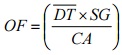
Figure 6-1a: Sketch of an Acceptable Sampling Train for Odour Sampling (Dynamic Dilution Approach)
This figure shows an arrow on the left hand side pointing to the right representing stack gas. The arrow is pointing to a probe, which is represented by a long thin rectangle. There is a line extending vertically through the middle of the probe representing an orifice. Above the probe there is a diagram of a nitrogen gas cylinder with a valve, which passes through an orifice and then to the right hand side of the probe orifice.
At the other end of the probe is a Teflon line, which turns ninety degrees and is connected to a valve that exhausts to the right. The bend is also connected to a valve at a ninety degree angle and is connected to a Tedlar bag.
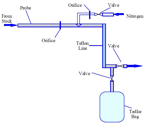
Figure 6-1b: Sketch of an Acceptable Sampling Train for Odour Sampling (Evacuated Lung Approach)
This figure shows an arrow on the left hand side pointing to the right representing stack gas. The arrow is pointing to a probe, which is represented by a long thin rectangle. At the other end of the probe is a Teflon line connected to a Tedlar bag inside a sampling lung. There is another Teflon line connected to the outlet of the sampling lung and to a pump.
Figure 6-1c: Sketch of an Acceptable Sampling Train for Odour Sampling (Flux Chamber Approach)
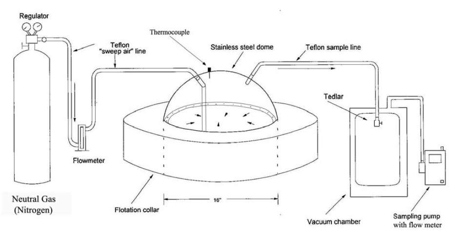
This figure shows the sampling train for a flux chamber. There is a compressed gas cylinder of neutral gas (nitrogen) on the left hand side, with a regulator on top. There is a Teflon line coming from the regulator, connected to a flow meter. There is another Teflon line on the other side of the flow meter which is connected to the top of the flux chamber on the left side. The flux chamber has a round stainless steel dome and a thermocouple on the top and is connected to a floatation collar. The stainless steel dome has a diameter of 16 inches, with a Teflon sampling line connected to the top of the dome on the right side. This line leads to a Tedlar bag that is inside a vacuum chamber. The vacuum chamber has a Teflon line connected to a sampling pump with a flow meter.
Source - Diagram modified for Ontario specifications based on the following document: Murphy, Scott (2009) Missoula Odor Characterization Study. Morrison-Maierle Inc. & Bowker & Associates Inc.
Figure 6-1d: Sketch Of An Acceptable Sampling Train For Odour Sampling (Biofilter Bed Sample Train)
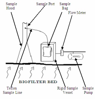
This figure shows a sampling train for a biofilter bed. The bottom of the figure represents a biofilter bed, with squiggly arrows representing odour coming from the bottom to the top. There is an upside down “Y” shaped sample hood on top of the biofilter bed with a long narrow stem representing the sample port. There is a Teflon line in the stem part of the sample hood approximately one third the way from the top. The Teflon line is connected to a sample bag inside a rigid sample vessel. There is another Teflon line from the rigid sample vessel connected to a flow meter and to a sample pump.
Figure 6-2: Odour Sampling Flux Chamber Configuration
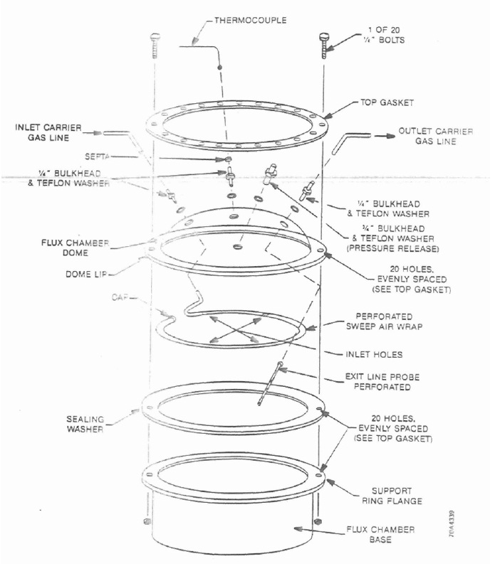
This figure shows parts of a flux chamber in a deconstructed view. The top layer is a top gasket with quarter inch holes evenly placed around the gasket. The cylinder-shaped gasket is hollow, with an inner diameter of approximately 16 inches. The top gasket has two, quarter inch bolts that are inserted on the right and left ends of the cylinder. The next layer is the flux chamber dome. The dome has three holes evenly spaced on the top for quarter inch bulkheads and Teflon washers. The hole on the left has a Teflon inlet carrier gas line. The hole in the middle has a thermocouple and the hole on the right has a Teflon line for the outlet carrier gas line. There are 20 holes evenly spaced on the dome lip that align with the top gasket. The next layer is a perforated sweep air wrap with four inlet holes at 90 degrees to each other. The next layer is a sealing washer with 20 holes evenly spaced as the same as the top gasket and dome lip. The final layer is the flux chamber base with a support ring flange. This flange has the same 20 evenly spaced holes. The quarter inch bolts that are inserted into the top gasket connect to all the layers except the perforated sweep air wrap.
Source: U.S. Environmental Protection Agency (1986). Measurement of gaseous emission rates from land surfaces using isolation flux chamber - user’s guide.
Figure 6-3: Trucks Odour Sampling Station
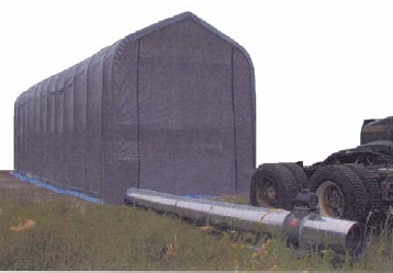
This figure shows a picture of a truck enclosure for a truck odour sampling station. The enclosure is large enough to fit a tractor trailer sized truck and has a rectangular base with a pointed top. It is fully enclosed and sealed to the outside environment. There is a circular tube made of sheet metal that extends outwards from inside the building along the ground.
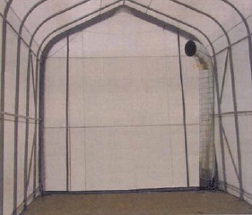
This figure shows the inside of the truck enclosure. It has a circular sheet metal tube to attach to the truck to exhaust the fumes outside of the truck enclosure.
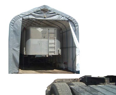
This figure shows a truck inside the truck enclosure. The entrance is lifted up and the truck is fully inside the truck enclosure.