11. Flowing Test Holes & Dewatering Wells
Chapter Description
This chapter describes flowing wells
Regulatory Requirements – Flowing Wells
Relevant Sections – The Wells Regulation
- Flowing Well Definition – Subsection 1(1)
- Flowing Wells – Section 14.7
- Venting – Section 15.1
- Abandonment – Section 21.1
The Requirements – Plainly Stated
The Wells Regulation requires the following when a flowing well is encountered:
Construction and Device
If the test hole or dewatering well becomes a flowing well during well construction:
-
the person constructing the well must ensure that the test hole or dewatering well is constructed to accommodate and be compatible with a device that:
- controls the discharge of water from within the well casing,
- is capable of stopping the discharge of water from within the well casing,
- is capable of withstanding the freezing of water in the well casing, and
- is installed on or in the test hole or dewatering well.
-
the construction of the test hole or dewatering well and the device installed must prevent any:
- uncontrolled flow of water from the well or at the well site, and
- backflow of water into the well or well casing.
Abandonment Option
The requirements listed above do not apply if the test hole or dewatering well is abandoned according to the Wells Regulation (for further details see Chapter 17: Abandonment: How to Plug & Seal Test Holes & Dewatering Wells).
Costs
Every contract between the well purchaser and the well contractor for the construction of a test hole or dewatering well is deemed to contain a term that makes the well contractor responsible for the costs of:
- complying with the above requirements and
- abandoning the well, if applicable.
This is the case irrespective of whether the contract is written or verbal or whether this responsibility is explicitly written into the contract or not. The only exception is if there is a written contract between the well contractor and well purchaser that specifically releases the well contractor from these costs.
Venting Exemption
A new test hole or dewatering well in which the casing is used to transmit water out of the well (e.g., flowing well without a well pump) does not need to meet air vent requirements. For further requirements for venting when a pump is installed in a flowing dewatering well see Chapter 12: Equipment Installation.
- Flowing well
- A well that has a static water level above the ground surface.
- Static water level
- The level attained by water at equilibrium in a well when no water is being taken from the well.
Reminder: The shallow works exemptions in the Wells Regulation do not apply if the test hole or dewatering is constructed in an area with conditions likely to result in flowing wells.
Relevant Sections – Additional Regulations or Legislation
- Fisheries Act (R.S., 1985, c. F-14)
- Ontario Water Resources Act, R.S.O. 1990, Chapter O. 40: Sections 30 (Impairment) and 34 to 34.2 (Permit To Take Water), section 53 (Sewage Works)
- Ontario Regulation 387/04 (Water Taking) as amended made under the Ontario Water Resources Act, R.S.O. 1990, Chapter O. 40
Key Concepts
What is a flowing well?
A "flowing well" means a well that has a static water level above the adjacent ground surface. Flowing wells occur when water pressure in the aquifer causes the water level to rise above the ground surface.
There are several things that are important to know with respect to flowing wells:
- In the majority of cases, only confined aquifers hold the potential for flowing wells
- Strong artesian (hydrostatic head) pressure forces groundwater above the ground surface to create a flowing well (see Figure 11-1)
- There are specialized construction techniques and devices that are used when constructing a well in flowing conditions to control the free flow of groundwater from the test hole or dewatering well
- Improper construction can lower the aquifer’s hydraulic pressure, waste groundwater and create flooding problems
- Elevation and loadings (e.g., recharge, discharge) are two hydrogeological factors that create conditions for development of flowing wells (see Figure 11-3)
- Aquifer recharge events and groundwater withdrawals affect the groundwater level which may lead to intermittent flowing conditions
Figure 11-1: Flowing Test Hole
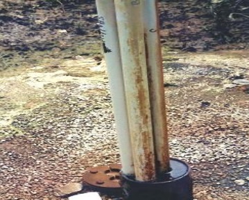
Figure 11-1 shows four casings of a nested multi-level test hole extending out of the ground. This test hole is located near a waste disposal site. Even though it is difficult to see in the photograph, groundwater containing leachate is flowing from cracks in the plastic casing down into the permanent outer casing. The groundwater spills out of the permanent outer casing onto the ground surface. The groundwater containing leachate has caused iron staining on the casing and ground surface. The leachate may cause an adverse effect on the natural environment.
Figure 11-2: Flowing Test Hole
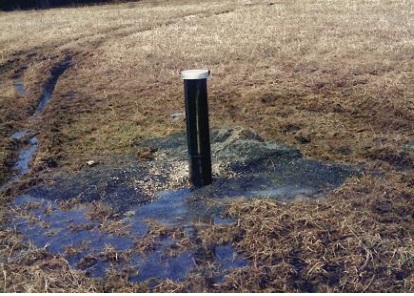
Figure 11-2 shows a permanent outer casing that surrounds a nested multi-level test hole with seals (not shown). This test hole is located near a waste disposal site. Groundwater containing leachate is flowing out of the inner casings and filling up the outer casing. Once full, the groundwater containing leachate flows between the well cap and permanent outer casing onto the ground surface. The flowing groundwater has caused a flooding problem in the vicinity of the well. The discharged leachate may also cause an adverse effect on the natural environment.
Figure 11-3: Geological Conditions that Create Flowing Wells
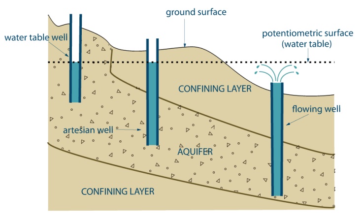
Figure 11-3 is a cross-section diagram to explaining the geological conditions that cause flowing wells. The ground surface and geological units in the subsurface are shown to slope downward to the right. There are three wells that have been constructed into the subsurface.
The well on the left has been constructed into a sand and gravel subsurface material. There is a confining layer (for example clay or silt) below the sand or gravel subsurface material. As a result, water from precipitation will migrate down through the sand and gravel from the ground surface and collect in the sand and gravel forming an aquifer. The top of the aquifer is called the water table. As there is no pressure exerted by a confining material on top of the sand and gravel, the water level in the well is exactly the same as the potentiometric surface (or water table). This type of well (on the left) is called a water table well.
The well in the centre has been constructed through a confining layer (for example, clay or silt) and is completed into the sand and gravel subsurface material that contains the aquifer. The weight of the upper confining layer exerts a positive pressure on the water aquifer in the subsurface. When the well in the centre is constructed through the confining layer into the aquifer, the positive water pressure is released causing the water to rise up the hole until the water level reaches the same pressure as the atmosphere. As the water level is above the actual level of the aquifer, the potentiometric surface (water table) is shown to be above the actual location of the aquifer at and around the well in the centre. This type of well (in the centre) is called an artesian well.
The well on the right has been constructed in a similar fashion as the well in the centre; however, the ground surface at the well on the right is at a significantly lower elevation than the well in the centre. As positive pressure in the aquifer is the same in both wells, the potentiometric surface (or water table) is actually above the ground surface at the location of the well on the right. When the water level rises in the well to achieve an equal pressure with the atmosphere, the water pressure causes the water to flow out of the well onto the ground surface. This type of well (on the right) is called a “flowing well”.
Reminder: This figure is not to scale, it is for illustrative purposes only and does not necessarily represent full compliance with other requirements found in the Wells Regulation.
Why Regulate Flowing Wells?
It is essential to control flowing wells to:
- conserve groundwater resources,
- prevent adverse effects to the natural environment such as property damage, discharge of contaminated groundwater, flooding, sediment deposition, erosion and surface water impacts,
- preserve the pressure within the aquifer, and
- prevent the creation of a direct pathway for contaminants.
Construction Considerations When Flowing Conditions are Encountered
There are several factors that should be considered (see Table 11-1 below) when predicting the occurrence of flowing well conditions and when constructing test holes or dewatering wells in areas where flowing conditions may occur. Details are provided on the following pages.
| Phase | Consideration |
|---|---|
| I. Predicting a Flowing Well |
|
| II. Designing a Flowing Well |
|
Phase I: Predicting a Flowing Well
The following provides two ways to predict the likelihood of a flowing well:
Consideration 1: Analyzing the Surrounding Physical Setting and Local Knowledge
Possible indicators of a flowing well include a valley location or areas where nearby surface water is at a higher elevation than the area of the proposed well site. The person constructing the test hole or dewatering well should check for other flowing wells and "springs" in the area. Visible flow of water at the surface or wet soil conditions may be indicators of flowing well conditions. The person constructing the well or local residents may have general knowledge of the area that suggests possible flowing well conditions.
Consideration 2: Examining Well Records and Existing Hydrogeological Reports for the Area
Obtaining well records from the Ministry of the Environment and Climate Change (see the Resources section of this manual) for nearby wells is an important step in understanding the types of aquifers in the area and should be done prior to beginning construction. In addition, in some areas of Ontario, hydrogeological reports have been produced that identify aquifers that may produce flowing wells. These hydrogeological reports may be found at the local office of:
- Ministry of the Environment and Climate Change
- Municipality
- Conservation Authority
Phase II: Designing a Flowing Well
For each type of geology, and depending on the type of construction equipment, there are factors that should be considered to ensure an efficient test hole or dewatering well (see Table 11-1 and design considerations 3, 4 and 5 below).
Best Management Practice – Planning to Control the Flow
Prior to beginning construction in a region known to have flowing well conditions, it is essential that a plan be in place to control the flow. The person constructing the well should consider retaining a Professional Geoscientist or Professional Engineer (consultant) experienced in hydrogeology and flowing well conditions to design the test hole or dewatering well. If the person constructing the well is unfamiliar with the area or with flowing well conditions, it is important that a licensed well contractor and well technician (of the correct class) experienced with flowing wells be consulted. In some cases, creating a small diameter pilot hole may be appropriate to determine subsurface conditions.
Consideration 3: Determining the Geologic Conditions
To properly design the test hole or dewatering well, the geological and hydrogeological environment has to be assessed. This knowledge will determine the best construction process for the well. For example, two different environments requiring different well designs are as follows:
- Competent bedrock has been encountered and a sufficient length of casing has been installed. The person constructing the test hole or dewatering well may need to seal the casing into the bedrock with a proper concrete grout to ensure flowing water will not rise up through the annular space of the well. The person constructing the well would then continue to advance the smaller diameter hole inside the casing down to the confined aquifer in the bedrock.
- A thick [e.g., 30 m (100ft)] clay layer has been encountered above a sand and gravel formation (confined aquifer). The person constructing the test hole or dewatering well may need to advance a large diameter hole and casing to just above the top of the aquifer. Next, the person may need to seal the annular space of the larger diameter casing into the clay and then advance a smaller diameter hole and casing through the larger casing into the aquifer. Finally, the person would install a seal between the two casings to ensure flowing water will not rise up through the annular space between the well casings.
Consideration 4: Determining Depth, Pressure and Flow of Aquifer
The location of the recharge zones, thickness of confining layers, elevation of the ground surface and physical characteristics of the aquifer will determine the likelihood of encountering flowing well conditions. A person constructing a test hole or dewatering well should accurately determine this information or plan for the worst case scenario.
Important terms
- Piezometric level
- The level to which groundwater in a confined aquifer will rise within a well when no water is being taken from the well. It is the same as the static water level (see in Chapter 2: Definitions & Clarifications, Table 2-1). In the case of a flowing well, the piezometric level is above the ground surface. It is not possible to look at the volume of an artesian well discharge and determine the elevation of the piezometric level. The piezometric level is expressed in metres (or feet) above ground surface.
- Artesian head
- The hydraulic pressure created within the confined aquifer that drives the water upward in a well to the piezometric level. The distance from the ground surface to the piezometric level, converted into equivalent pressure [expressed as kilopascals (kPA) or pound force per square inch (psi)], is the artesian head.
- Downhole hydrostatic head pressure (or DHHP)
- The hydrostatic pressure at the top of the artesian aquifer, which results from the combination of the artesian head and a water column extending from the top of the artesian aquifer to the ground surface [expressed as kilopascals (kPA) or pound force per square inch (psi)].
- Downward grout pressure (or DGP)
- The pressure that must be exerted by the grout (sealant) in order to equalize the DHHP [expressed as kilopascals (kPA) or pound force per square inch (psi)] and stop the flow.
Determining Pressures and Elevations:
Determining pressures and elevations involves measurement, calculations and observations.
Reminder: When using metric units, the exact pressure conversion from 1 m of height of water equals 9.8 kPa.
Artesian Head and Piezometric Level (or Static Water Level)
Two methods for measuring artesian head and static water level are as follows:
- Installing a pressure gauge on top of the enclosed casing.
Reading the gauge will provide a measurement in either kilopascals (kPa) or pounds force per square inch (psi). This will provide the artesian head.
To convert the pressure readings to distance the following conversions are used:
1 kPa = 0.1 m
1 psi = 2.31 ftMultiplying the artesian head kPa pressure reading by 0.1 m (or the psi pressure reading by 2.31 ft will provide the elevation of the piezometric level (or static water level) in metres (feet) above the elevation of the pressure gauge.
piezometric level (metres) = artesian head (kPa) × 0.1 (m/kPa)
piezometric level (feet) = artesian head (psi) × 2.31 (ft/psi)Measuring the distance between the elevation of the pressure gauge to the ground surface and then adding the result to the calculated piezometric elevation will provide the piezometric (static water level) elevation above the ground surface.
- Installing a casing extension to contain the flowing water.
The water level inside the extended casing above the ground surface is measured. The result will provide the piezometric level (static water level) in metres (feet) above the ground surface.
To convert the distance measurement to pressure the following conversions are used:
1 m = 10.0 kPa
1 ft = 0.433 psiMultiplying the piezometric level (or static water level) by 10 kPa (or 0.433 psi) will provide the artesian head pressure in kPa (or psi) above the ground surface.
artesian head (kPa) = piezometric level (metres) × 10 (kPa/m)
artesian head (psi) = piezometric level (feet) × 0.433 (psi/ft)As an alternative, a small diameter tube that extends to a sufficient height above ground level to contain the static water level can be attached to the closed casing. The water level inside the small diameter tube above the ground surface is measured. The result will provide the piezometric level (static water level) in metres (feet) above the ground surface. The conversion calculation in method 2 (above) is then used to obtain the artesian head pressure.
Best Management Practice – Determining Pressure Prior to Well Construction
To obtain information about local piezometric head (static water level) conditions in flowing well areas prior to constructing the well, a person constructing a well can, in combination with following the best management practice titled "Planning to Control the Flow":
- measure the pressure at a nearby flowing well using a pressure gauge and follow the procedures in method 1 (above) if a nearby flowing well has been constructed with an appropriate control device. As an alternative, the person could follow method 2 (above).
- obtain static water level, aquifer and pressure information for an area from hydrogeological reports.
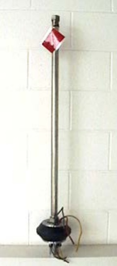
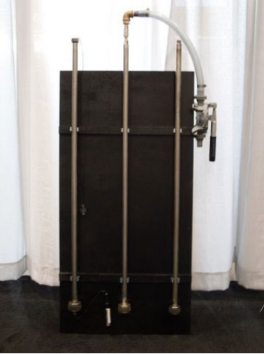
Figure 11-4: Flowing Well Pressure Gauge Device

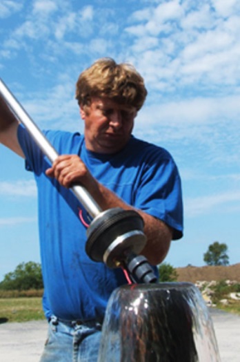
Figure 11-5: Flowing Well Pressure Gauge Device - Installed
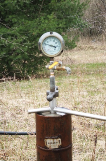
Figure 11-4 and Figure 11-5 show a flowing well pressure gauge device. It is made with an EPDM rubber packer that is sealed between two stainless steel plates at the bottom of the device. A steel rod with a tightening device and pressure gauge is installed to the packer (Figure 11-4). The packer is installed into the top of the well casing (Figure 11-5). Using the tightening rod, the steel plates squeeze the EPDM rubber to the sides of the well casing which pressurizes the water column. The pressure is detected by the device through the steel rod into the gauge. The gauge provides the artesian head pressure at the elevation of the gauge.
Reminder: Pressure gauge devices should only be used on new and existing wells that will not allow groundwater to flow up and around the well casing.
Downhole Hydrostatic Head Pressure (DHHP)
To determine the pressure at the top of the aquifer, add the measured or calculated piezometric level (static water level) in metres (feet) above the ground surface to the measured level of the top of the aquifer encountered in the well in metres (feet) below the ground surface. For example, if the peizometric level is 10 m above the ground surface and the depth to the top of the aquifer is 40 m below the ground surface, then the total distance of the two measurements combined is 50 m (i.e., 10 + 40).
To convert the distance measurement to pressure the following conversions are used:
1 m = 10.0 kPa
1 ft = 0.433 psi
Multiplying the distance in metres (feet) between the piezometric level (or static water level) to the top of the aquifer by 10 kPa (0.433 psi) will provide the downhole hydrostatic head pressure (DHHP) at the top of the aquifer.
Using the above example, a distance of 50 m (164 ft) multiplied by 10 kPa (0.433 psi) results in a DHHP of 500 kPa (71 psi).
Downward Grout Pressure (DGP)
To contain the flow of groundwater going up the well, the downward grout pressure of the material must overcome the downhole hydrostatic head pressure.
In calculating the downward grout pressure (DGP), manufacturers supply fluid densities of mixtures of bentonite and cement in kilograms per litre (kg/L), pounds per American gallon (lbs/US gal) and in some cases pounds per Imperial gallon (lbs/Imp gal).
To covert a fluid density to pressure, the multiplication factor of 9.8 can be used for metric units, 0.043 for Imperial units and 0.052 for American units.
Therefore, DGP can be calculated by:
DGP (kPa) = Grout density (kg/L) × 9.8 × depth to top of artesian aquifer (metres) or
DGP (psi) = Grout density (lbs/gal) × 0.043 × depth to top of artesian aquifer (feet) or
DGP (psi) = Grout density (lbs/US gal) × 0.052 × depth to top of artesian aquifer (feet)
Example of how to apply the DGP:
In the previous example, the DHHP was calculated to be 500 kPa (71 psi). The top of the aquifer is 40 m from the ground surface. The multiplication factor is 9.8.
Therefore, to determine if a 40 m column of cement mixed with water to a density of 1.8 kg/L will stop the flow and if a 40 m column of bentonite mixed with water to a density of 1.2 kg/L will stop the flow:
The DGP of cement = 1.8 kg/L × 9.8 × 40 m = 705.6 kPa.
The DGP of bentonite = 1.2 kg/L × 9.8 × 40 m = 470.4 kPa.
Since the DGP of cement is 205.6 kPa greater than the DHHP of the aquifer, the cement will likely stop the flow.
Since the DGP of bentonite is 29.6 kPa less than the DHHP of the aquifer, the bentonite will likely not stop the flow and thus, groundwater will continue to discharge out of the well.
Reminder: See the "Tools," section of this chapter for kPa and psi conversions.
Consideration 5: Determining Well Construction Equipment And Site-Specific Design
As with the design of any well, the equipment and methods used should be considered prior to breaking ground (see Chapter 6: Constructing the Hole, Casing & Covering the Test Hole or Dewatering Well, for details). When designing a well that is to be installed in an area in which flowing conditions may be encountered, there are additional considerations and equipment that may be required to control the flow.
Test hole or dewatering well design considerations should include:
-
Drilling systems:
-
Typical drilling systems that are used:
- Rotary (mud, air, reverse)
- Dual rotary
- Cable tool
-
Systems that are generally not recommended for use when flowing conditions may be encountered:
- Augering
- Boring and digging
- Jetting
- Driving
-
-
Grouting Materials:
-
The extra density of cement grouts (i.e., they have a higher downward grout pressure) may allow them to overcome the downhole hydrostatic head pressure better than lighter bentonite slurries. Some grouting materials include:
- Cement based (e.g., neat cement, high-early strength)
- Neat cement slurry with accelerator (e.g., calcium chloride)
- Concrete
- Bentonite slurry
- Weighting agent (barite) added to bentonite slurry
-
-
Other considerations that affect the design of a flowing well include:
- Depth
- Diameter
- Single casing vs. multiple casing
- Screened well vs. open bottom
- Overburden vs. bedrock aquifer formation
- Naturally developed vs. gravel pack screen
- Aquifer water quality (e.g., high sulphates may affect certain types of cement grout material and high total dissolved solids may affect bentonite)
- Use of the well (e.g., test hole, dewatering, municipal, domestic, monitoring, industrial, commercial)
-
Approvals:
- The potential requirement to obtain a Permit to Take Water (PTTW) from the Ministry, or any other approval is an important consideration and should be determined prior to the construction of the well.
Reminder: A Permit to Take Water under the Ontario Water Resources Act may be required when the flow of groundwater freely discharges from a test hole or dewatering well at a rate that is greater than 50,000 L on any one day (11,000 gal/day). Therefore, it is important that the person constructing the test hole or dewatering well estimate the taking before constructing the well. If the estimate shows the flow will take more than 50,000 L on any one day, then the person constructing the test hole or dewatering well may need to obtain a Permit To Take Water from the Ministry prior to construction. If during construction the person takes more than 50,000 L of water in one day without a permit, the person may be subject to enforcement (e.g., orders and charges). More information on Permit To Take Water approvals can be found in Chapter 5: Siting Considerations & Initial Planning and on Ontario.ca.
Reminder: A sewage works environmental compliance approval under the Ontario Water Resources Act may be required if the person discharges the water from the well owner’s property and the discharge capacity exceeds 10,000 litres per day. It is important for the person to determine if an environmental compliance approval is required before discharging the well water during the testing of the well yield. A guide to explain the sewage works process can be found on Ontario.ca.
Concerns when Encountering Flowing Conditionsfootnote 3
The additional considerations, including planning, materials, expertise and equipment needed to properly construct a well under flowing conditions, can result in substantial costs not associated with routine well construction. If a flowing well is constructed improperly, the ensuing costs are likely to be even greater as discussed below.
Damage from flow breakout may cause the following incidents:
- The uncontrolled discharge of groundwater from flowing wells can cause flooding of the well site and adjacent properties and damage to nearby structures.
- Silt, clay, gravel, sand, and drilling fluids can be carried along with the artesian groundwater to the ground surface and eventually reach surface water. This can alter the quality of the surface water and impact the habitat of aquatic organisms.
- Colder water temperatures from a flowing well discharge can alter the habitat of warm water aquatic species.
- The uncontrolled discharge of groundwater from flowing wells can cause loss of water pressure and water supply to neighbouring wells.
- The uncontrolled discharge of groundwater affects groundwater pressures measured in the flowing hole and the surrounding area. Such conditions may result in underestimation of actual groundwater pressures to be expected at a project site. This can seriously affect the technical feasibility of the project, the construction techniques, the safeguards required and the cost of the project.
- Flow along the outside of the casing can quickly enlarge the hole and form subsurface voids.
- A large volume of geologic material can erupt during a breakout or blowout and create unstable, hazardous conditions at the surface.
Cost of Flowing Conditions
Improper construction, repairs, maintenance and abandonment of a flowing well can be costly.
Unanticipated costs that may arise from flowing conditions include extensive damage to property, restoration of the environment and regulatory enforcement (e.g., orders and charges).
Costs associated with individual flowing wells can be in the tens of thousands of dollars and have exceeded one million dollars in Ontario.
Permits and Other Regulatory Approvals
As indicated, flowing wells may require a Permit To Take Water from the Ministry of the Environment and Climate Change if the flow of groundwater is discharging out of the well at more than 50,000 L on any one day during construction or after construction. Other discharge approvals may be necessary if the groundwater from the flowing well discharges into other waters such as a lake, creek or river. Obtaining these permits and approvals can be expensive and time consuming for both the person constructing the well and the well owner.
Best Management Practice – Avoiding Flowing Well Conditions in an Uncased Test Hole or Dewatering Well
The person constructing the test hole or dewatering well should not create an uncased well through an area prone to flowing well conditions. Groundwater discharging from a flowing test hole or dewatering well could cause one or more of the following:
- Flooding, erosion and other property damage
- Contaminants to discharge to the surface that may cause an adverse effect to the natural environment
- A change in groundwater gradients causing the plume of contaminants to move in an unwanted direction
- Unexpected and significant expenses to meet the Wells Regulation’s flowing well construction requirements or abandonment requirements
Figure 11-6: Creation of Subsurface Void
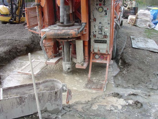
Figure 11-6 shows the back of an orange drilling rig. A black drilled well casing extends out of the muddy water through a rotary table. The drilling rig is holding on to the casing with the rotary table and a welded piece of steel. During drilling the flow around the outside of the casing created a void in the ground. The overburden above the void has collapsed creating a 10 metre (30 foot) deep by 4 metre (13 foot) wide hole filled with water. The void was unknown until the time of overburden collapse. The void created a serious safety issue for anyone working on the back of the drilling rig.
Figure 11-7: Creation of Subsurface Void
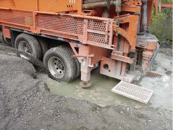
Figure 11-7 shows the same drilling rig and void shown in Figure 11-6. The drilling rig is slowly falling into the hole, jeopardizing the drilling rig. In this case, the well contractor took immediate measures to fill the void and rescued the drilling rig.
Discharge (Flow) Controlfootnote 4
The Wells Regulation requires that an appropriate device be installed on a well that becomes a flowing well. The device must control the discharge of water from within the well casing. The test hole or dewatering well must be constructed and the device must be installed in a way that prevents any uncontrolled flow of water from the test hole or dewatering well or at the well site. The device must be capable of stopping the discharge from within the well casing, must be capable of withstanding the freezing of water in the well casing and must be compatible with the well.
Proper control of discharge water from a flowing well consists of:
- controlling, and if necessary, stopping the discharge of water from within the well casing, and
- preventing the discharge of water from around the casing by tightly sealing the juncture between the hole wall and the well casing (annular space) and in some cases between two well casings.
A device can consist of one or many components installed in or connected to a well. The following are two examples:
- An air vacuum valve, or a combination air vacuum valve and air release valve, may need to be installed on a flowing well packer (Figure 11-8 to Figure 11-10).
- An in-line ball-valve may need to be installed in the waterline or plumbing when using a multiple drawdown seal.
The following sections in this chapter provide examples of devices and methods that are compliant with the Wells Regulation and some that are not compliant.
Compliant Devices and Methods
When selecting a flow control device, it is important to consider the environmental conditions (e.g., freezing), well design and water pressure within the well. A device should be assessed to determine if it can withstand the pressure exerted by the water in the well.
There are a variety of devices that can control the flow from within the well casing. The following are examples of flow control devices and methods:
- Flowing well packer (Figure 11-8 to Figure 11-12)
- Drawdown seals (sometimes called flowing well packer) with clamp on pitless adapter (Figure 11-13)
- Flowing well pitless unit, spool type (Figure 11-14)
- Extending the casing above the static water level elevation
- Installing a watertight well cap or welded plate to the top of the well casing
Reminder: Figure 11-8 to Figure 11-14 illustrate some examples of compliant devices and methods which meet the Wells Regulation requirements for controlling and, if necessary, stopping the flow of water within the well casing.
Figure 11-8: Flowing Well Packer
This photograph shows a flowing well packer unit. The unit consists of a packer located at the bottom of a long stainless steel rod. The length of the rod allows the packer to be placed below the frost line. The packer is made out of black EPDM rubber between two stainless steel plates.
The bottom of the packer is equipped with an air vacuum valve or a combined air vacuum and air release valve to ensure that air can move into and out of the well but water cannot.
The photograph shows the packer area comes equipped with proper gauged electrical cables. Electrical wiring from the submersible pump in the well can be attached to the cables in the bottom of the unit. Electrical cables can be attached to the top of the packer to allow the wiring to extend out of the well and connect to the electrical service.
At the top of the steel bar is a nut. A socket wrench can be attached to the nut and can turn the steel bar. When installed in the well, turning the bar squeezes the plates and expands the packer to the sides of the well casing.
The manufacturer should be consulted to ensure the various parts of the unit can withstand the pressure exerted by the water column.
Reminder: See Figure 11-9 and Figure 11-10 for further information on the installation of the flowing well packer.
Reminder: An air vacuum relief valve is designed to allow air to enter into a system and vent air out of a water system rapidly. Once the water encounters the valve, the weighted ball in the valve seals to the plate in the valve creating a watertight seal, an air release valve allows any gas build up in the water column to slowly vent from the water column while maintaining a watertight seal.
Reminder: If a pump is installed in a drilled well, an air vacuum relief valve and, if necessary, a combined air vacuum relief and air release valve must be installed on the drawdown seals to vent the well.
Reminder: Proper safety precautions and warnings should be provided to all persons who will be repairing and servicing wells with these types of devices as the high water pressure can force packers to be pushed out of a flowing well at high velocity.
Figure 11-9: Flowing Well Packer
The flowing well packer shown in Figure 11-9 is being installed in a drilled well that is freely flowing.
At the bottom of the packer is the combined air vacuum valve and air release valve.
The packer is made out of black EPDM rubber between two stainless steel plates. The person installing the device will push the packer into the drilled well using the stainless steel bar.
The red and black electrical wires are also shown extending through watertight seal areas in the packer. Electrical wiring from the submersible pump in the well can be attached to the wires in the bottom of the unit. Electrical wiring can be attached to the top of the unit to allow the wiring to extend out of the well and connect to the electrical service.
The manufacturer should be consulted to ensure the unit can withstand the pressure exerted by the water column.
Figure 11-10: Flowing Well Packer
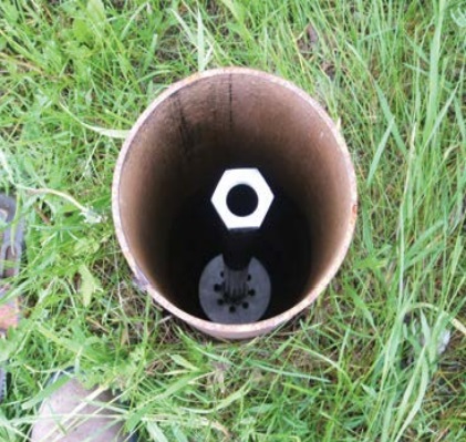
Figure 11-10 shows the flowing well packer installed in the well. A socket wrench has been used to turn the nut attached to the steel bar. Turning the bar forces the steel plates together, expands the EPDM rubber to the side of the steel casing creating a watertight seal and shuts the flowing water off below the frost level.
Typically, a pitless adapter, drop pipe and pump are installed below the flowing well packer. Electrical wires run from the service to the well, through the top of the well casing and attach to the wiring on the packer. Electrical wires from the submersible pump in the well attach to the electrical wires on the bottom of the packer. A typical vermin-proof well cap can be installed on top of the well casing with an air vent and a plug in the electrical conduit.
Figure 11-11: Flowing Well Packer for Small Diameter Test Hole
The three stainless steel flowing well packers shown in Figure 11-11 are similar to the one shown in Figure 11-9 and Figure 11-10 except these three packers are sized to fit in smaller diameter test holes (e.g., 5 centimetres in diameter). The center packer shows a waterline and valve attached to the top of the device for sampling purposes.
Figure 11-12: Flowing Well Packer For Small Diameter Test Hole With Datalogger
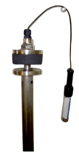
Figure 11-12 shows a flowing well packer for a small diameter test hole (e.g., less than 5 centimetres) that is similar to the packers shown in Figure 11-11. This packer, however, has been placed in the inverted position to show how a cable can extend from the packer to a pressure transducer/datalogger or other type of monitoring device.
Figure 11-13: Flow Control Using Drawdown Seals (With Clamp-On Pitless Adapter)
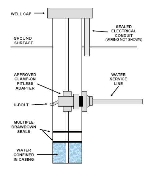
Figure 11-13 is a cross-section diagram of a flow control using draw down seals (with clamp-on pitless adapter).
The diagram shows the upper portion of a well. The well consists of casing that extends vertically from above the ground surface to a distance below the ground surface. A vermin-proof well cap has been placed on top of the casing. The ground surface is shown as being horizontal around the well. On the right side exterior of the casing, an electrical conduit (wiring not shown) extends from the ground surface into the bottom of the vermin-proof well cap. Inside the casing, a hold down pipe extends from the bottom of the vermin-proof well cap, through the approved clamp-on pitless adapter then through multiple draw down seals and into the bottom of the well. An approved clamp-on pitless adapter is attached to the interior of the casing above the multiple drawdown seals. There is a U-bolt at the left side of the pitless adapter. Confined water is shown inside the casing below the multiple drawdown seals. On the right side of the casing, a horizontal water service line extends from the casing at the approved pitless adapter to the right side of the diagram.
Reminder: This figure is not to scale, it is for illustrative purposes only and does not necessarily represent full compliance with other requirements found in the Wells Regulation (e.g., proper mounding).
Reminder: If a pump is installed in a drilled well, an air vacuum relief valve and, if necessary, a combined air vacuum relief and air release valve must be installed on the drawdown seals to vent the well.
Reminder: The manufacturer should be consulted to ensure the unit can withstand the pressure exerted by the water column.
Reminder: Drawdown seals (with clamp-on pitless adapters) can be difficult to repair and service. Proper safety precautions and warnings should be provided to all persons who will be repairing and servicing wells with these types of devices as the high water pressure can force the seals to be pushed out of a flowing well at high velocity.
Figure 11-14: Flow Control Using Flowing Well Pitless Unit – Spool Type
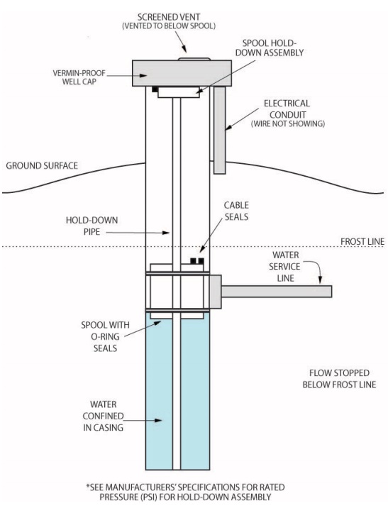
Figure 11-14 is a cross-section diagram of a flow control using a flowing well pitless unit – spool type.
The diagram shows the upper portion of a well. In the upper portion of the subsurface, there is a horizontal dotted line that represents the frost line. The well consists of casing that extends vertically from above the ground surface to a distance below the ground surface. A vermin-proof well cap has been placed on top of the casing. A screened vented (vented to below the spool) is located on top of the vermin-proof well cap. On the right side exterior of the casing, an electrical conduit (wire not shown) extends from the ground surface into the bottom of the vermin-proof well cap. The ground surface is mounded away from the well’s casing. Inside the casing, a spool-hold down assembly is attached to the bottom of the vermin-proof well cap. Inside the casing, a hold down pipe extends from the spool-hold down assembly, through the spool and into the bottom of the well. A spool with O-rings is attached to the interior of the casing below the frost line. There are two cable seals on the top of the spool. Confined water is shown inside the casing below the spool. On the right side of the casing, a horizontal water service line extends from the casing at the spool to the right side of the diagram.
There is text on the lower right side of the diagram that states “flow stopped below the frost line”. There is text below the bottom of the well that states “see manufacturer’s specification for rated pressure (psi) for hold-down assembly.
Pitless units have built-in pitless adapters. The pitless unit shown in Figure 11-14 has a spool and is typically used for industrial and municipal wells.
A vermin-proof well cap, sealed to the top of the well casing, and a spool hold the assembly below the cap and hold the spool in place.
The spool consists of rubber rings attached to steel plates. The rings and plates seal to the casing above and below a casing connection to the horizontal pipe. The spool confines the water below the frost line in the well casing. The spool also has areas that allow for electrical cables to run to the submersible pump in the well.
Reminder: This figure is not to scale, it is for illustrative purposes only and does not necessarily represent full compliance with other requirements found in the Wells Regulation (e.g., proper mounding).
Reminder: If a pump is installed in a drilled well, an air vacuum relief valve and, if necessary, a combined air vacuum relief and air release valve must be installed on the system to vent the well.
Reminder: The manufacturer should be consulted to ensure the unit can withstand the pressure exerted by the water column.
Raising the Well Casing, Installing a Watertight Well Cap or Installing a Welded Cap
In some cases, raising the casing above the static water level elevation or installing a watertight well cap or welded plate on the top of a well casing can stop the flow of water out of the top of the well casing.
In these cases, water above the frost line is prone to freezing in the winter. Casing and caps must be made and installed to withstand cold temperatures and freezing.
If a pump is installed in a flowing drilled well, raising the casing or placing a watertight well cap may not be an appropriate device because the well needs to be vented.
Reminder: Watertight well caps and welded plates on wells can be difficult to repair and service. Proper safety precautions and warnings should be provided to all persons who will be repairing and servicing wells with these types of devices as the high water pressure can force the caps or plates to be pushed out of a flowing well at high velocity.
Non-Compliant Devices and Methods
Figure 11-15 to Figure 11-18 illustrate some examples of non-compliant devices and methods that do not control the flow in accordance with the Wells Regulation.
Reminder: Figure 11-15 to Figure 11-18 are not to scale and are for illustrative purposes for this chapter only. The diagrams are only intended to show the non-compliant flow control method/device and not intended to show other aspects of regulatory compliance (e.g., proper mounding).
Figure 11-15: Non-Compliant Annular Flow – Discharge Piping
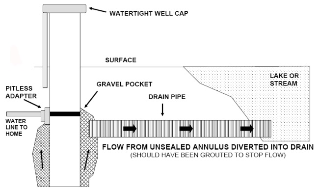
Figure 11-15 is a cross-section diagram of an unapproved annular flow – discharge into a drain, river or stream.
The diagram shows the upper portion of a well. The well consists of casing that extends vertically from above the ground surface to a distance below the ground surface. A watertight well cap has been placed on top of the casing. The ground surface is shown as being horizontal around the well. A lake or stream is located on the right side of the diagram. On the left side exterior of the casing, an electrical conduit (wire not shown) extends from the ground surface into the bottom of the well cap. On the left side of the casing and below the ground surface, a pitless adapter has been connected to the casing. A horizontal waterline extends from the pitless adapter to the left side of the diagram. There is an annular space around the casing that extends from the pitless adapter to the bottom of the diagram. The annular space has been filled with gravel. On the right side of the well at about the same depth as the horizontal water line, there is a horizontal drain pipe. The horizontal drain pipe extends from the gravel to a lake or stream. There are arrows pointing upward in the gravel that demonstrates how the pressurized groundwater flows up the gravel zone to the horizontal drain pipe. There are arrows in the drain pipe going from the well to the lake or stream that demonstrates how the pressurized groundwater flows from the well to the lake or stream.
There is text below the horizontal drain pipe that states “flow from unsealed annulus diverted to drain (should have been grouted to stop flow)”.
Figure 11-16: Non-Compliant Buried Flow Discharge Piping With Check Valve, Confining Layer Not Sealed
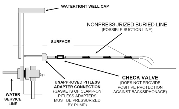
Figure 11-16 is a cross-section diagram of an unapproved buried flow discharge piping with check-valve, confining layer not sealed.
The diagram shows the upper portion of a well. The well consists of casing that extends vertically from above the ground surface to a distance below the ground surface. A watertight well cap has been placed on top of the casing. The ground surface is shown as being horizontal around the well. On the right side of the diagram, the ground surface slopes downward. On the left side exterior of the casing, an electrical conduit (wire not shown) extends from the ground surface into the bottom of the well cap. On the left side of the casing and below the ground surface, a pitless adapter has been connected to the casing. A horizontal water service line extends from the pitless adapter to the left side of the diagram.
On the right side of the well and at a little higher elevation than the horizontal water service line, a clamp-on pitless adapter has been connected to the casing. The clamp-on pitless adapter connection is unapproved because gaskets of clamp-on pitless adapters must be pressurized by a pump. A horizontal non-pressurized buried line (possible suction line) extends from the pitless adapter through the downward sloping ground surface. Near the clamp-on pitless adapter, a check valve has been placed in the horizontal non-pressurized buried line. There is text associated with the check valve that states “does not provide positive protection against back-siphonage”).
There are arrows in the horizontal non-pressurized buried line going from the well to the end of the pipe that demonstrates how the pressurized groundwater flows from the well and discharges out onto the ground surface.
Reminder: Figure 11-15 and Figure 11-16 are not to scale and are for illustrative purposes for this chapter only. The diagrams are only intended to show the non-compliant flow control method/device and not intended to show other aspects of regulatory compliance (e.g., proper mounding).
Figure 11-17: Non-Compliant Control Valve
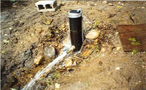
Figure 11-17 shows that if the valve is shut off, groundwater will overflow the well through the well cap. In this case, water is flowing out of the well even with the valve open.
Figure 11-18: Non-Compliant Buried Flow Discharge Piping With Submerged Inlet
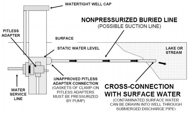
Figure 11-18 is a cross-section diagram of an unapproved buried flow discharge piping with submerged inlet.
The diagram shows the upper portion of a well. The well consists of casing that extends vertically from above the ground surface to a distance below the ground surface. A watertight well cap has been placed on top of the casing.The ground surface is shown as being horizontal around the well. A lake or stream is located on the right side of the diagram. On the left side exterior of the casing, an electrical conduit (wire not shown) extends from the ground surface into the bottom of the well cap. On the left side of the casing and below the ground surface, a pitless adapter has been connected to the casing. A horizontal water service line extends from the pitless adapter to the left side of the diagram.
On the right side of the well and at a little higher elevation than the horizontal water service line, a clamp-on pitless adapter has been connected to the casing. The clamp-on pitless adapter connection is unapproved because gaskets of clamp-on pitless adapters must be pressurized by a pump. A horizontal non-pressurized buried line (possible suction line) extends from the pitless adapter through the downward sloping ground surface.
There are arrows in the horizontal non-pressurized buried line going from the well to the end of the pipe that demonstrates how the pressurized groundwater flows from the well and discharges out to the lake or stream. There is a note associated with the horizontal non-pressurized buried line that states “cross connection with surface water (contaminated surface water can be drawn into well through submerged discharge pipe)”.
Reminder: Figure 11-17 and Figure 11-18 are not to scale and for illustrative purposes for this chapter only. The diagram is only intended to show the non-compliant flow control method/device and not intended to show other aspects of regulatory compliance (e.g., proper mounding).
Constructing a Test Hole or Dewatering Well in Flowing Conditions
Before construction begins in a region that is susceptible to flowing conditions, it is essential to have a plan to control the flow of water. The person constructing the well should consider retaining a Professional Geoscientist or Professional Engineer to design the test hole or dewatering well as suggested in the "Best Management Practice - Planning to Control the Flow," in this chapter. If the person constructing the well is unfamiliar with the area or with flowing well conditions, it is important that a licensed well contractor and well technician (of the correct class) experienced with flowing wells be consulted. In some cases, creating a small diameter pilot hole may be appropriate to determine subsurface conditions.
Flowing Wells Using Common Construction Methods
Some common approaches for test hole or dewatering well construction when flowing conditions are encountered are described below.
Casing Selection
The selection of casing materials and wall thickness must take into account the water pressures involved and the potential for freezing. For example, plastic is not recommended for use in flowing conditions.
Some forms of casing (e.g., plastic) may be structurally weakened by some types of sealants (e.g., heat of hydration from cement grouts).
Because of the large pressure exerted on the casing, the depth to the artesian flowing aquifer is an important consideration in ensuring the structural integrity of the casing. Knowing the depth of the artesian flowing aquifer will aid in determining the appropriate depth, wall thickness and diameter of the permanent outer casing(s).
Casing Installation
For overburden aquifers, a permanent outer casing should be installed and grouted into the confining layer before an inner well casing is installed through the confining layer into the top of the aquifer.
For bedrock aquifers, a drive shoe should be attached to the bottom of the casing and then seated securely into the bedrock to create a seal.
If a person drills through more than one confining layer and aquifer during well construction, the outer casing, when used, must be sealed into the lowest confining layer prior to advancing an inner casing into the aquifer with flowing artesian conditions.
Constructing an oversized hole compared to casing diameter is also extremely important to ensure an adequate volume of sealant is placed in the annular space to contain the flow of any water.
It is important to take extra care to centre the casing in the oversized hole using devices such as centralizers. Centering the casing creates an appropriate annular space around the casing to ensure that proper grout placement can occur along the entire length of the casing.
Long strings of casing should be kept under tension, not compression, during grouting.
Weighting Materials
Drilling and driving a casing into the hole can allow groundwater to escape in an uncontrolled fashion when a flowing well is encountered. Therefore, when dealing with flowing wells, it is common to use drilling fluid (drilling mud) with weighting material to control water while drilling proceeds and ensure that the hole does not collapse prior to casing installation.
Weighting materials such as barite can be used to:
- increase drilling fluid density while maintaining a proper solids/fluid ratio,
- control formation pressure, and
- stabilize hole.
Considerations when selecting a weighting material may include:
- specific gravity,
- quality (e.g., purity),
- degree of corrosiveness and abrasiveness, and
- chemical inertness
As with grout, the specific gravity of the drilling fluid with weighting material must overcome the downhole hydrostatic head pressure (see the "Phase II: Designing a Flowing Well", "Consideration 4: Determining Depth, Pressure and Flow of Aquifer," section of this chapter).
Reminder: It is important to follow the manufacturer’s recommended specifications when using drilling fluid with weighting materials. Manufacturers will have tables and guidelines to assist in obtaining the correct drilling fluid density (see Figure 11-19).
Figure 11-19: Densities of Common Fluids Used in Well Construction
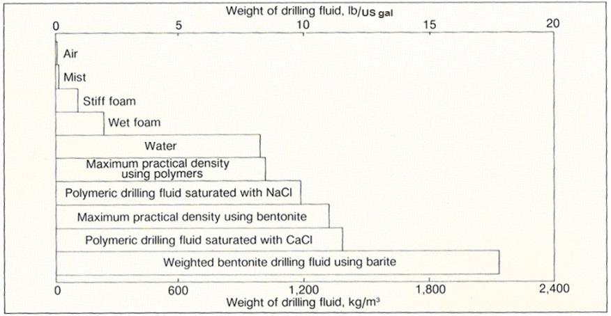
Figure 11-19 is a chart showing densities of common fluids in well construction.
The chart consists of two horizontal lines showing density values in standard and metric units. The upper horizontal line shows weight of drilling fluid in pounds per U.S. gallon (standard units). The standard unit horizontal line is marked in increments of 5, starting at zero and ending at 20. The lower horizontal line shows weight of drilling fluid in kilograms per cubic metre (metric units). The metric unit horizontal line is marked in increments of 600, starting at zero and ending at 2,400.
Between the horizontal rectangles between the horizontal lines that represent ten types of materials. The type of material and its density are shown in the diagram as follows:
- Air – less than 1 pounds per U.S. gallon or less than 1 kilogram per cubic metre
- Mist – about 1 pounds per U.S. gallon or less than 10 kilograms per cubic metre
- Stiff foam – about 1.5 pounds per U.S. gallon or less than 100 kilograms per cubic metre
- Wet foam - about 2 pounds per U.S. gallon or about 100 kilograms per cubic metre
- Water - about 7 pounds per U.S. gallon or about 1,000 kilograms per cubic metre
- Maximum Practical Density using Polymers - about 7.5 pounds per U.S. gallon or about 1,100 kilograms per cubic metre
- Polymeric drilling fluid saturated with sodium chloride - about 10 pounds per U.S. gallon or about 1,200 kilograms per cubic metre
- Maximum Practical Density using Bentonite - about 11 pounds per U.S. gallon or about 1,300 kilograms per cubic metre
- Polymeric drilling fluid saturated with calcium chloride - about 12 pounds per U.S. gallon or about 1,300 kilograms per cubic metre
- Weighted bentonite drilling fluid using barite - about 17 pounds per U.S. gallon or about 2,000 kilograms per cubic metre
“Practical drilling fluid densities range from virtually zero for air, to greater than 1,800 kg/m3 (15 lbs/gal) for bentonite with barite additives. In general, the density of the drilling fluid must be high enough to balance any confined pressure conditions in the hole. Excessive drilling fluid densities, on the other hand, cause high fluid losses, plugging of the aquifer, unsatisfactory cuttings removal in the mud pit, and higher than necessary pumping costs.”
Grouting
Grout (suitable sealant) must be properly placed in the annular space to prevent flowing water problems.
In addition to the methods and considerations described in Chapter 7: Annular Space & Sealing, the rate of flow and water pressures must be considered when selecting a grouting method for a flowing well (see Table 11-2 to Table 11-4 in the “Tools” section in this chapter).
The selection of grouting material and required specific density were previously described in the “Phase II: Designing a Flowing Well, Consideration 5: Determining Well construction Equipment and Site-Specific Design” section of this chapter.
Cement based grouts need to properly set (or cure) to the manufacturer’s specifications or 12 hours (whichever is longer).
Cement slurries with accelerators such as calcium chloride can allow for quicker set times to prevent dilution, washouts and voids (subsurface erosion) around the casing.
Knowledge of how grouts cure (or hydrate), and experience with mixing and placement of grout is important to ensure that the selected sealant (grout) will perform adequately to contain the flow of water.
When grouting a flowing well, extra materials [e.g., cement, calcium chloride (accelerator), fresh water for mixing, extra tremie lines and fittings, weighting agent (e.g., barite and gel products)] should be on hand and ready for use.
In some cases, the well may be pumped to lower the water level in the hole to allow the placement of a filter pack and the installation of grout.
Flowing Wells Using Other Construction Methods
The use of construction methods such as boring, digging, augering, jetting and driving are generally not recommended where flowing conditions may be encountered. These methods typically pose greater risks and may require additional or different precautions to contain the flow.
Dug, Bored or Driven Point Wells
The vast majority of dug, bored and driven point wells are relatively shallow and are located in unconfined aquifers, resulting in a lower likelihood of encountering flowing conditions; however, flowing well conditions can still be encountered during shallow well construction (e.g., near surface water bodies). It is important to take into consideration the indicators of flowing conditions (see the "Phase I: Predicting a Flowing Well," section of this chapter) even when constructing these types of wells.
Auger Construction
Auger methods, such as hollow stem or continuous flight augering, are not recommended if flowing conditions are expected. Augering construction presents serious complications if flowing conditions are encountered since casing and weighting materials are not installed during the augering process. Extra caution should be taken when using augering equipment before breaking through a confining formation and into the aquifer. If caution is not taken and flowing conditions are encountered, it will be difficult to install and seal any type of casing into the confining formation to control the groundwater from the flowing well.
Direct Push and Sonic Construction
Direct push and sonic methods are not recommended if flowing conditions are expected. Direct push and sonic methods do not typically involve the use of drilling fluids, which can be weighted to prevent flowing conditions from occurring. As a result, it would be difficult to install and seal any type of casing into the confining formation to control the groundwater from the flowing well.
Best Management Practice – Seeking Second Party Advice
If the person constructing the well has limited experience with flowing well conditions and there is any possibility of an occurrence of a flowing well while using any of the above construction methods, a Professional Geoscientist, Professional Engineer or experienced licensed well technician working for a licensed well contractor should be called to obtain expert advice before starting. The person should also use this best management practice in combination with the "Best Management Practice – Planning to Control the Flow," in this chapter.
Some Successful Construction Methods
Figure 11-18 to Figure 11-22 illustrate some methods that have been used successfully in the past when encountering flowing conditions. However, it is important that the design for each flowing well be based on site-specific conditions. See the "Phase II: Designing a Flowing Well," section of this chapter for details regarding construction considerations when flowing conditions are encountered.
Reminder: The figures on the following pages are not to scale, are for illustrative purposes for this chapter only and diagrams do not necessarily represent full compliance with other requirements found in the Wells Regulation (e.g., proper mounding). See Chapter 7: Annular Space & Sealing for further details.
Confined Aquifer in Bedrock (Figure 11-20 to Figure 11-22)
If the confined aquifer is located in solid bedrock and the bedrock is at or near the ground surface, the drill hole should be significantly oversized and larger than the outer diameter of the casing. The annular space must be sealed to contain (i.e., stop the movement of) any flowing water in the annular space. This can be accomplished by using neat cement placed in the annular space and allowing it to cure to the manufacturer’s specifications, for example.
Figure 11-20: Confined Bedrock Aquifer
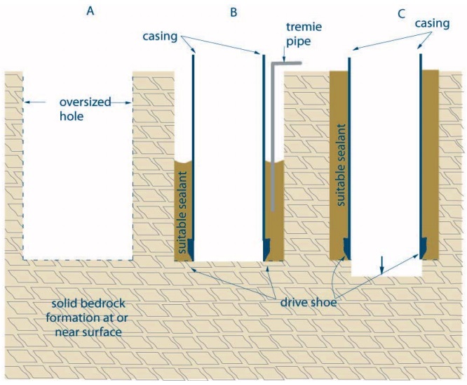
Construction method for Figure 11-20 can be cable tool, rotary air or down-the-hole hammer.
Step A.
Initial hole near the top of the flowing aquifer and diameter is significantly oversized compared to the finished diameter of the casing, to a depth of at least 6 m (20ft). A greater depth may be required to encounter competent rock or to ensure containment.
Step B.
A smaller diameter casing is installed and centred in the oversized hole. The annular space is filled with a suitable grout/sealant that can withstand the downhole hydrostatic head pressure of the aquifer (for details on sealing the annular space see Chapter 7: Annular Space & Sealing).
Step C.
The hole is drilled out the bottom of the inner casing to the flowing artesian aquifer.
Step D.
A compatible flow control device is installed on the well [see "Discharge (Flow) Control," section in this chapter]. Casing must stick up at least 40 cm (16 inches) above the highest point on the ground surface within 3 m (10 ft) radially from the outside of the well casing.
Reminder: The figure above is not to scale, it is for illustrative purposes for this chapter only and does not necessarily represent full compliance with other requirements found in the Wells Regulation (e.g., proper mounding).
Figure 11-21: Bedrock Aquifer With Confining Overburden Layer - Multiple Casings and Weighted Materials
Construction method for Figure 11-21 can be rotary with drilling mud
Step A.
A significantly oversized hole is drilled with weighted drilling fluids (mud) into the confining overburden formation to a depth that is near the top of the confined aquifer. Note: the hole is oversized compared to the outer casing.
Step B.
The outer casing is centred and set to bottom of oversized hole. The annular space is filled with a suitable grout/sealant that can withstand the downhole hydrostatic head pressure of the aquifer.
Step C.
The hole is drilled out through the bottom end of the casing into the top of the aquifer using weighted drilling fluids (mud). The hole diameter is similar to inner diameter of outer casing.
Step D.
The inner casing is set to the top of the aquifer and sealed in place with suitable sealant as described in Step B.
Step E.
After following recommendations to allow grout to set, drilling can continue into the flowing artesian aquifer.
Step F.
A compatible flow control device is installed on the well [see "Discharge (Flow) Control," section in this chapter]. Casing must stick up at least 40 cm (16 inches) above the highest point on the ground surface within 3 m (10 ft) radially from the outside of the well casing.
Reminder: The figure above is not to scale, it is for illustrative purposes for this chapter only and does not necessarily represent full compliance with other requirements found in the Wells Regulation (e.g., proper mounding).
Reminder: When the confined aquifer is located within consolidated material (bedrock), the inner casing should be driven or a smaller diameter hole drilled and the inner casing set firmly into the bedrock.
Reminder: The annular space around the entire inner casing must be filled from the bedrock to ground surface with suitable sealant. The sealant must be able to withstand the aquifer’s downhole hydrostatic head pressure.
Figure 11-22: Bedrock Aquifer With Confining Overburden Layer - Multiple Casings and Temporary Casing
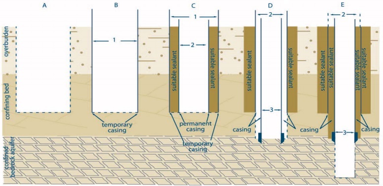
Construction method for Figure 11-22 can be cable tool, rotary air and dual rotary.
Step A.
A significantly oversized hole is drilled (1).
Step B.
The temporary outer casing (2) is advanced into the confining overburden formation to a depth that is near the top of the confined aquifer. The casing is usually installed at the same time as drilling if formation is susceptible to collapsing.
Step C.
The permanent outer casing is centred and set to bottom of oversized hole. The annular space between temporary and permanent casings is filled with a suitable grout/sealant that can withstand the downhole hydrostatic head pressure of the aquifer. The temporary casing (1) is removed.
Step D.
The hole is drilled out through the bottom of the casing (2). The hole diameter is similar to the inner diameter of the outer casing (2). Weighted drilling fluids (mud) may be used to contain the flow. An inner casing (3) is installed to the bottom of the hole seated into bedrock and sealed in place with suitable sealant as described in C.
Step E.
The annular space between inner (3) and outer (2) permanent casings is filled with a suitable grout/sealant that can withstand the downhole hydrostatic head pressure of the aquifer. After following recommendations to allow grout to set, drilling can continue into the bedrock to the flowing artesian aquifer.
Step F.
A compatible flow control device is installed on the well [see "Discharge (Flow) Control," section in this chapter]. Compatible flow control device is installed on the well [see Discharge (Flow) Control section in this chapter]. At least one casing must stick up at least 40 cm (16 inches) above the highest point on the ground surface within 3 m (10 ft) radially from the outside of the well casing.
Reminder: The diagram above is not to scale, it is for illustrative purposes for this chapter only and does not necessarily represent full compliance with other requirements found in the Wells Regulation (e.g., proper mounding).
Reminder: When the confined aquifer is located within consolidated material (bedrock), the inner casing should be driven or a smaller diameter hole drilled and the casing set firmly into the bedrock.
Reminder: The annular space around the entire inner casing must be filled from the bedrock to ground surface with suitable sealant. The sealant must be able to withstand the aquifer’s downhole hydrostatic head pressure.
Confined Aquifer in Overburden Where Flowing Conditions are Expected (Figure 11-23 to Figure 11-24)
The well should be double cased as a minimum and the annular space should be pressure grouted.
Another method that may be used to control flowing conditions is to set a permanent outer casing, install a packer at the bottom of the casing, install the inner casing, and pressure grout through the packer between the two casings.
The outer casing should be adequately sealed into the impermeable layer so as to prevent surface and subsurface leakage from the artesian aquifer.
It is important not to extend (i.e., drill) too far into these types of overburden aquifers as high water pressures can cause piping (subsurface erosion), wash outs and crevasses to form around the casing during drilling.
Figure 11-23: Overburden Aquifer with Confining Layer - Multiple Casings and Weighted Materials
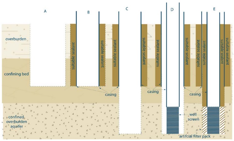
Construction method for Figure 11-23 can be rotary with drilling mud.
Step A.
A significantly oversized hole is drilled with weighted drilling fluids (mud) into the confining overburden formation to a depth that is near the top of the confined aquifer. Note: the hole is oversized compared to the outer casing.
Step B.
The outer casing is centred and set to bottom of oversized hole. The annular space is filled with a suitable grout/sealant that can withstand the downhole hydrostatic head pressure of the aquifer.
Step C.
The hole is drilled out through the bottom of the casing into the top of the flowing aquifer using weighted drilling fluids (mud). The hole diameter is similar to inner diameter of outer casing.
Step D.
The inner casing and well screen are centred and set into aquifer with weighted mud.
Step E.
The artificial filter pack is placed around well screen. The annular space from the top of the filter pack, including between permanent casings, is filled with a suitable grout/sealant that can withstand the downhole hydrostatic head pressure of the aquifer.
Step F.
A compatible flow control device is installed on the well [see “Discharge (Flow) Control,” section in this chapter]. At least one casing must stick up at least 40 cm (16 inches) above the highest point on the ground surface within 3 m (10 ft) radially from the outside of the well casing.
Reminder: The diagram above is not to scale, it is for illustrative purposes for this chapter only and does not necessarily represent full compliance with other requirements found in the Wells Regulation (e.g., proper mounding).
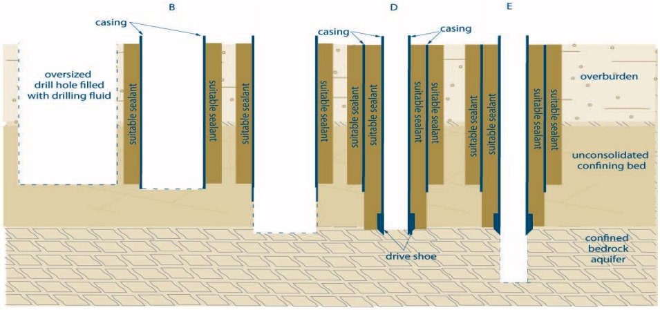
Figure 11-24: Overburden Aquifer With Confining Layer - Multiple Casings and Temporary Casing
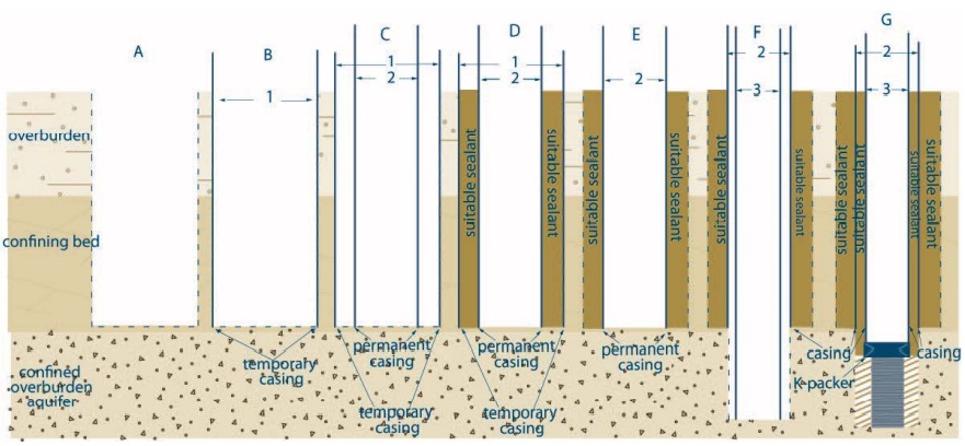
Construction method for Figure 11-24 can be cable tool, rotary air and dual rotary.
Step A.
A significantly oversized hole is drilled into the confining overburden formation to a depth that is near the top of the confined aquifer.
Step B.
A temporary outer casing (1) is advanced into the confining overburden formation to a depth that is near the top of the confined aquifer. Note: the hole is oversized compared to the permanent outer casing.
Step C.
The permanent outer casing (2) is centred and set to bottom of temporary casing.
Step D.
The annular space between temporary (1) and permanent (2) casings is filled with a suitable grout/sealant that can withstand the downhole hydrostatic head pressure of the aquifer.
Step E.
The temporary casing (1) is removed
Step F.
The hole is drilled out through the bottom of the casing (2) while advancing an inner casing (3) into the top of the aquifer. The hole diameter is similar to the inner diameter of the permanent outer casing. Weighted drilling fluids (mud) may be used to contain the flow.
Step G.
A telescopic well screen is installed at bottom of casing and the casing is pulled back to expose the well screen to the formation. The annular space between inner and outer permanent casings is filled with a suitable grout/sealant that can withstand the downhole hydrostatic head pressure of the aquifer.
Step H.
A compatible flow control device is installed on the well [see Discharge (Flow) Control section in this chapter]. At least one casing must stick up at least 40 cm (16 inches) above the highest point on the ground surface within 3 m (10 ft) radially from the outside of the well casing.
Reminder: The diagram above is not to scale, it is for illustrative purposes for this chapter only and does not necessarily represent full compliance with other requirements found in the Wells Regulation (e.g., proper mounding).
Well Contractor Responsible for Costs
Wells Regulation - If a test hole or dewatering well becomes a flowing well during construction (including installing a pump and any alterations), the well contractor is responsible for the cost of complying with the flowing well construction or abandonment requirements in the Wells Regulation (see the "Plainly Stated," section in this chapter).
This includes the following actions and any costs associated with them:
-
The proper construction of the well that prevents any uncontrolled flow from the well (which includes the area around the well casing) or at the well site and the installation of an appropriate device in or on the well that:
- controls the discharge of water from within the well casing,
- is capable of stopping the flow of water from within the well casing,
- is capable of withstanding the freezing of water in the well casing, and
- prevents the backflow of water into the well; or
- The abandonment of the well in accordance with the Wells Regulation requirements (see Chapter 17: Abandonment: How to Plug & Seal Test Holes & Dewatering Wells).
Wells Regulation - Every contract between the well purchaser and the well contractor for the construction of a test hole or dewatering well is deemed to contain a term that makes the well contractor responsible for the costs of:
- complying with the above requirements and
- abandoning the well, if applicable.
Reminder: This is the case irrespective of whether the contract is written or verbal or whether this responsibility is explicitly written into the contract or not. The only exception is if there is a written contract between the well contractor and well purchaser that specifically releases the well contractor from these costs.
Reminder: Even if the well contractor is relieved from the costs, the person constructing the well must still meet the Wells Regulation requirements to control or abandon the flowing well, as stated in the "Plainly Stated," section in this chapter.
Encountering a Flowing Well Unexpectedly
When constructing a test hole or dewatering well including deepening of an existing well, the installation of a pump or another alteration, it is possible that a flowing well situation may be unexpectedly encountered. This is a situation that can become seriously problematic very quickly. It is important to always be prepared and know:
- How to control and stop an unexpected flowing well as explained in this chapter.
- How to abandon an unexpected flowing well as explained in Chapter 17: Abandonment: How to Plug & Seal Test Holes & Dewatering Wells.
Consulting a Professional
Best Management Practice – Consulting a Professional
The person constructing the well should immediately retain a Professional Geoscientist or Professional Engineer (consultant) experienced in hydrogeology and flowing well conditions, to assess the unexpected flowing well and the hydrogeology around the flowing well.
After the consultant has assessed the flowing well and the hydrogeology around the well, the consultant should provide the person constructing the well with recommendation(s) to either abandon the well or to properly construct the well and install an appropriate device to control and, if necessary, shut off the flow of water from the well.
The person constructing the well should immediately implement the consultant’s recommendations to prevent any adverse effects such as flooding. As a suggestion, the person constructing the well could have the consultant observe the rectification operation at the flowing well to ensure the recommendations are followed.
Installing Pumps in Existing Flowing Wells or Where a Well Becomes a Flowing Well After It Has Been Constructed
There are many health and safety concerns when working on existing flowing wells with control devices. The high pressures in the water column can cause devices, such as packers, and portions of the adapters, to be pushed out of a flowing well at high velocities. There have been cases where people have been seriously injured trying to remove control devices.
The removal of devices has also resulted in flooding problems, the discharge of contaminated well water into surface water and flows exceeding 50,000 litres per day without a Permit To Take Water from the Ministry.
It is important that proper safety and environmental precautions [including obtaining any environmental approvals such as a Permit To Take Water (see Permits and Other Regulatory Approvals section in this chapter)] be observed by anyone who will be repairing and servicing wells with these types of devices to avoid injury and protect the environment.
There are also many concerns when working on existing flowing wells that do not have control devices. See the "Concerns when Encountering Flowing Conditions" section in this chapter for some of the legal liabilities.
Best Management Practice – Consulting a Professional for Existing Flowing Wells
Prior to working on an existing flowing well or if a well suddenly becomes a flowing well, consider retaining a Professional Geoscientist or Professional Engineer (consultant) experienced in hydrogeology and flowing well conditions to assess the flowing well and the hydrogeology around the flowing well.
After the consultant has assessed the flowing well and the hydrogeology around the well, the consultant should provide the person constructing the well or well owner with recommendation(s) to:
- properly upgrade the well,
- abandon the well and construct a new well, or
- install an appropriate flow control device.
The consultant’s recommendations should be implemented. If a person constructing the well is unfamiliar with the area or with repairing flowing wells, it is important that a licensed well contractor and well technician (of the correct class) experienced with flowing wells be consulted and if necessary, retained to do the work.
Tools
| Depth to top of flowing aquifer from ground surface in metres. | Pressure from grout in kPa with Density of 1.8 kg/L | Pressure from grout in kPa with Density of 1.25 kg/L | Pressure from grout in kPa with Density of 1.14 kg/L | Downhole hydrostatic pressure in kPa for various piezometric levels above ground surface measured at 1 m | Downhole hydrostatic pressure in kPa for various piezometric levels above ground surface measured at 2 m | Downhole hydrostatic pressure in kPa for various piezometric levels above ground surface measured at 4 m | Downhole hydrostatic pressure in kPa for various piezometric levels above ground surface measured at 6 m | Downhole hydrostatic pressure in kPa for various piezometric levels above ground surface measured at 8 m | Downhole hydrostatic pressure in kPa for various piezometric levels above ground surface measured at 10 m |
|---|---|---|---|---|---|---|---|---|---|
| 3 | 53* | 37** | 34† | 39** | 49** | 69* | 88* | 108* | 127* |
| 6 | 106* | 74** | 67† | 69† | 78** | 98** | 118* | 137* | 157* |
| 10 | 176* | 123** | 112† | 108†† | 118† | 137** | 157** | 176* | 196* |
| 15 | 265* | 184** | 168† | 157†† | 167†† | 186** | 206** | 225** | 245** |
| 20 | 353* | 245** | 223† | 206†† | 216†† | 235† | 255** | 274** | 294** |
| 25 | 441* | 306** | 279† | 255†† | 265†† | 284† | 304† | 323** | 343** |
| 30 | 529* | 368** | 335† | 304†† | 314†† | 333†† | 353† | 372** | 392** |
| 35 | 617* | 429** | 391† | 353†† | 363†† | 382†† | 402† | 421† | 441** |
| 40 | 706* | 490** | 447† | 402†† | 412†† | 431†† | 451† | 470† | 490** |
| 50 | 882* | 613** | 559† | 500†† | 510†† | 529†† | 549†† | 568† | 588† |
| 60 | 1058* | 735** | 670† | 598†† | 608†† | 627†† | 647†† | 666†† | 686† |
| 70 | 1235* | 858** | 782† | 696†† | 706†† | 725†† | 745†† | 764†† | 784† |
| 80 | 1411* | 980** | 894† | 794†† | 804†† | 823†† | 843†† | 862†† | 882†† |
Reminder: This table has been prepared using the conversion factor: 1 m = 9.8 kPa.
| Depth to top of flowing aquifer from ground surface in feet. | Pressure from grout in psi with Density of 15 lbs/US gal or 18 lbs/Imp gal | Pressure from grout in psi with Density of 10.4 lbs/US gal or 12.5 lbs/Imp gal | Pressure from grout in psi with Density of 9.5 lbs/US gal or 11.4 lbs/Imp gal | Downhole hydrostatic head pressure in psi for various piezometric levels above ground surface measured at 5 ft | Downhole hydrostatic head pressure in psi for various piezometric levels above ground surface measured at 10 ft | Downhole hydrostatic head pressure in psi for various piezometric levels above ground surface measured at 15 ft | Downhole hydrostatic head pressure in psi for various piezometric levels above ground surface measured at 20 ft | Downhole hydrostatic head pressure in psi for various piezometric levels above ground surface measured at 25 ft | Downhole hydrostatic head pressure in psi for various piezometric levels above ground surface measured at 30 ft |
|---|---|---|---|---|---|---|---|---|---|
| 10 | 8* | 5** | 5† | 6** | 9* | 11* | 13* | 15* | 17* |
| 20 | 16* | 11** | 10† | 11** | 13** | 15** | 17* | 19* | 22* |
| 30 | 23* | 16** | 15† | 15† | 17** | 19** | 22** | 24* | 26* |
| 40 | 31* | 22** | 20† | 19†† | 22** | 24** | 26** | 28** | 30** |
| 50 | 39* | 27** | 25† | 24†† | 26† | 28** | 30** | 32** | 35** |
| 75 | 59* | 41** | 37† | 35†† | 37† | 39† | 41** | 43** | 45** |
| 100 | 78* | 54** | 49† | 45†† | 48†† | 50† | 52† | 54** | 56** |
| 125 | 98* | 68** | 62† | 56†† | 58†† | 61†† | 63† | 65† | 67† |
| 150 | 117* | 81** | 74† | 67†† | 69†† | 71†† | 74† | 76† | 78† |
| 175 | 137* | 95** | 86† | 78†† | 80†† | 82†† | 84†† | 87† | 89† |
| 200 | 156* | 108** | 99† | 89†† | 91†† | 93†† | 95†† | 97†† | 100† |
| 225 | 176* | 122** | 111† | 100†† | 102†† | 104†† | 106†† | 108†† | 110†† |
| 250 | 195* | 135** | 124† | 110†† | 113†† | 115†† | 117†† | 119†† | 121†† |
Reminder: This table has been prepared using the conversion factor: 1 ft = 0.433 psi.
Reminder: Example of use of legend for Table 11-2 and Table 11-3 (shown above): Where the top of the aquifer is three metres below the ground surface and the piezometric level is 1 metre above the ground surface, the corresponding pressure is calculated to be 39 kPa. The * indicates a column of 3 metres (distance from ground surface to aquifer in well) of neat cement grout with a fluid density of at least 1.8 kg/L or neat cement grout with weight additives will overcome the aquifer’s downhole hydrostatic head pressure of 39 kPa. However, none of the common bentonite grouts listed will overcome the downhole hydrostatic head pressure. The listed bentonite grouts will not stop the flow of groundwater out of the well.
Reminder: The tables present common grouting products used in the industry to overcome flowing well conditions. It is important that persons trying to overcome flowing wells verify and calculate the density of the grouting mixture before using these tables.
Reminder: After mixing the material at the site, fluid density can be verified in the field using a mud balance.
Reminder: In Table 11-2 and Table 11-3 the top of the aquifer is added to the piezometric level above the ground surface. If the measurement is in metres, then the total measurement is multiplied by 10 to give the pressure in kPa.
Reminder: If the measurement is in feet, then the total measurement is multiplied by 0.433 to give the pressure in psi. For example, where the top of the aquifer is 3 m and the piezometric level is 1.5 m, then the total measurement is 4.5 m. 4.5 m × 10 converts to 45 kPa.
| Material | Density | Hydrostatic Pressure in kPa (or psi) per metre (or per foot) |
|---|---|---|
| Neat Cement at 23 L (6 US gal) water per sack: | 1.80 kg/L 18.0 lbs/gal 15.0 lb/US gal |
17.64 kPa/m 0.78 psi/ft 0.78 psi/ft |
| Bentonite Slurry Grout: | 1.25 kg/L 12.5 lbs/gal 10.4 lb/US gal |
12.25 kPa/m 0.54 psi/ft 0.54 psi/ft |
| Bentonite Slurry Grout: | 1.14 kg/L 11.4 lbs/gal 9.5 lb/US gal |
11.17 kPa/m 0.49 psi/ft 0.49 psi/ft |
Reminder: In Table 11-4 the conversion from fluid density to pressure is multiply by 9.8 for kg/L to kPa/m, 0.043 for lbs/gal to psi/ft and 0.052 for lbs/US gal to psi/ft.
Footnotes
- footnote[1] Back to paragraph A flowing well is defined as a well that has a static water level above the ground surface.
- footnote[2] Back to paragraph Michigan Department of Environmental Quality. 2005. Flowing Well Handbook. Michigan DEQ. Lansing, MI.
- footnote[3] Back to paragraph Michigan Department of Environmental Quality. 2005. Flowing Well Handbook. Michigan DEQ. Lansing, MI. Pp. 3 to 13
- footnote[4] Back to paragraph Michigan Department of Environmental Quality. 2005. Flowing Well Handbook. Michigan DEQ. Lansing, MI.
- footnote[5] Back to paragraph Michigan Department of Environmental Quality. 2005. Flowing Well Handbook. Michigan DEQ. Lansing, MI. Figure 4.
- footnote[6] Back to paragraph Michigan Department of Environmental Quality. 2005. Flowing Well Handbook. Michigan DEQ. Lansing, MI. Figure 7.
- footnote[7] Back to paragraph Michigan Department of Environmental Quality. 2005. Flowing Well Handbook. Michigan DEQ. Lansing, MI. Figure 8.
- footnote[8] Back to paragraph Michigan Department of Environmental Quality. 2005. Flowing Well Handbook. Michigan DEQ. Lansing, MI. Figure 9.
- footnote[9] Back to paragraph Sterrett, Robert J. 2007. Groundwater and Wells; Third Edition. Johnson Screens/a Weatherford Company. New Brighton, MN. P300.
- footnote[10] Back to paragraph Based on information taken from Flowing Well Handbook, modified from Appendix A, Page 44.
- footnote[11] Back to paragraph Based on information taken from Flowing Well Handbook, modified from Appendix A, Page 44.