8. Multi-level Monitoring Test Holes
Chapter Description
This chapter provides detailed information, construction requirements and annular space sealing requirements for new multi-level monitoring test hole installations. For hole, casing and well screen requirements the reader will generally be referred back to Chapter 6: Constructing the Hole, Casing & Covering the Test Hole or Dewatering Well. The reader will also be referred back to Chapter 7: Annular Space & Sealing for some annular space filling requirements. For further information on requirements and best management practices for dewatering wells and test holes other than multi-level monitoring test holes, the reader is referred to the other chapters in this manual.
Regulatory Requirements – Equipment Installation
Relevant Sections – The Wells Regulation
Casing and Well Screen – Section 13 including Subsection 13(20)
Annular Space – Sections/Subsections 14, 14.1, 14.1(2), 14.2, 14.2(3), 14.3, 14.3(2), 14.4, 14.4(4), 14.5, 14.5(3), 14.6
The Requirements – Plainly Stated – Installing the Equipment
The Wells Regulation - Requirements and exemptions when a person constructs a new multi-level monitoring test hole:
Casing and Well Screen
The casing and well screen requirements and exemptions in Chapter 6: Constructing the Hole, Casing & Covering the Test Hole or Dewatering Well apply to a new multi-level monitoring test hole.
Annular Space
New Test Hole Operating not Later than 180 Days after the Completion of the Well’s Structural Stage
Instead of following the annular space requirements listed in Chapter 7: Annular Space and Sealing, the person constructing a new multi-level monitoring test hole without a permanent outer casing must ensure that:
- there is no movement of water, natural gas, contaminants or other material between subsurface formations or between a subsurface formation and the ground surface in any annular space along a well casing or between overlapping casings, and
- the test hole is scheduled to be abandoned within 180 days of the completion of its structural stage.
New Test Hole Operating More than 180 days After the Completion of the Well’s Structural Stage
The person constructing the test hole must install a permanent outer casing for any new multi-level monitoring test hole that will be in operation for more than 180 days after the completion of the well’s structural stage.
Depending on the type of well construction method used, the person constructing the test hole must follow the requirements listed in Chapter 7: Annular Space & Sealing, Table 7-1 A and Table 7-1B, with necessary modifications, to create and seal any annular space beside the permanent outer casing.
As a necessary modification for a multi-level monitoring system installed using drilling, augering or sonic equipment, the depth of the annular space must extend from the ground surface to at least the bottom of the permanent outer casing or 6 m (19.7 feet), whichever is less.
When a smaller diameter casing, or casings, is/are installed within the permanent outer casing, the annular space between the casings of different diameters must be sealed with a suitable sealant to prevent the entry of surface water and other foreign materials.
If any groundwater is leaking into the annular space between the casings of different diameters, the annular space between the casings must be sealed, with necessary modifications, in accordance with Chapter 7: Annular Space & Sealing, Table 7-1 A and Table 7-1B. The annular space between casings of a well constructed by the use of a driven point is not required to be sealed in accordance with Chapter 7: Annular Space & Sealing, but is required to be sealed with a suitable sealant.
Necessary modifications can include creating a properly sized hole that allows for the installation of centralizers to centre and separate all casings.
Annular Space below the Permanent Outer Casing
Person Constructing a Well
Although a person constructing a well is not specifically required to seal the casings between well screens or ports in a multi-level monitoring test hole below the permanent outer casing; the person must do what is necessary as the Ontario Water Resources Act prohibits every person from discharging or causing or permitting the discharge of any material of any kind into any waters that may impair the quality of any waters. This includes prohibiting contaminated groundwater from impairing the quality of other groundwater zones when constructing a well.
Well Owner
Persons using the above professional judgement and the well owner should be aware of the following requirement.
If the test hole or dewatering well acts as a pathway for the movement of:
- natural gas,
- contaminants, or
- other materials
between subsurface formations (including aquifers) or between the ground surface and a subsurface formation and where the movement may impair the quality of any waters, the well owner, must do one of the following:
- take measures to prevent the movement of the above materials and ensure the measures are functional at all times, or
- immediately abandon the well.
Reminder: Further information on abandonment requirements is provided in Chapter 16: Abandonment: When to Plug & Seal Test Holes & Dewatering Wells and Chapter 17: Abandonment: How to Plug & Seal Test Holes & Dewatering Wells of this manual.
Reminder: The regulatory exemptions regarding sealing the annular space below the permanent outer casing allow for well technicians, engineers and geoscientists to use their professional expertise to design and install multi-level wells on a case by case basis, thereby enabling the testing and sampling of various groundwater intervals while preventing contamination.
Key Concepts
Multi-Level Monitoring Test Holes
There are many hydrogeological and chemical complexities when determining the location of dissolved contaminants in groundwater. Hydrogeologists need to think and model in three dimensions when attempting to characterize contaminant plumes that may impact groundwater resources.
A single sampling port (e.g., one well screen per well) position in the ground and aquifer:
- can locate the port at the wrong depth or
- can be constructed with a well screen that is too long
The position of the sampling port could create a number of problems, some of which include:
- a failure to detect the presence of a contaminant plume,
- a potential for a bias in sample results because fresh groundwater above or below a plume can mix with the plume’s contaminated groundwater in the well,
- a risk of non-representative data because single zones are either too short and do not represent (miss) critical hydraulic or hydrogeochemical features, or are too long, and provide measurements (hydraulic head, chemistry) of a non-representative unknown blended fluid mixture,
- a lack of understanding of potentially significant flow paths and/or barriers to flow in the groundwater system,
- the development of a two dimensional model instead of a three dimensional model of the contaminated plume, or
- improper location of remediation wells.
Because of the potential problems listed in the bullets above, the vertical extent of the aquifer and plume may not be properly characterized in 3 dimensions. This can result in a potential to underestimate the health and environmental concern to down-gradient receptors such as wells and surface water bodies.
To overcome the problem, groups of test holes completed at different depths can be installed at one location. Another option is to install multiple discrete sampling well screens or devices at several depths in a test hole to accurately locate the contamination plume in the groundwater and identify changes in hydraulic head. The second option is commonly called a multi-level monitoring system.
The screens or ports should be properly constructed and sealed to reduce the risk of cross-flow of groundwater and contaminants between screens or ports within the multi-level well. Reducing the risk of intermingling:
- provides quality assurance that samples from each discrete port or well screen are representative of the discrete zone in the groundwater, and
- reduces the risk of contaminants intermingling with and impairing fresh groundwater in the same or a different formation.
Reminder: When designing and constructing multi-level monitoring systems, it is important for a person involved in well design or construction to take a “cradle to grave” approach. See the Best Management Practice - “Cradle to Grave” Approach for Test Holes and Dewatering Wells in Chapter 5: Siting Considerations and Initial Planning.
Multi-Level Monitoring Systems
Various nested and dedicated multi-level monitoring wells (test holes) are used to accurately locate and monitor the vertical extent of plumes of contamination in groundwater.
The type and installation of the various multi-level monitoring wells are described below. Figure 8-1 to Figure 8-21 illustrate various systems and the components that are presently in use.
Bundled Multi-Level Monitoring Test Hole
Bundled multi-level monitoring test holes are designed to study groundwater in unconsolidated collapsing overburden formations such as sand.
Typically, a hole is constructed into the collapsing formation using direct push, auger or rotary drilling equipment. Measurements and observations are made about the location of the groundwater level and aquifer as the well construction equipment is being advanced into the ground. A temporary drill rod, auger flight or pipe is installed during the construction of the hole to hold the hole open.
A bundle of tubing is installed into the temporary rod or pipe. The temporary rod or pipe is removed allowing the unconsolidated overburden to collapse around the bundle of tubing.
A commonly used bundle design will consist of a number of flexible or rigid tubes of different lengths affixed together using a binding tape. In another bundle design, up to 20 tubes are affixed to a larger diameter rigid PVC casing core. The tubing’s inside diameter typically ranges from 0.8 to 1.25 cm (0.3 to 0.5 inches). The bottom of each tube is plugged with a sealing product such as epoxy cement. The bottom 10 cm (4 inches) of each tube is slotted or perforated and covered with a fine nylon mesh. The length of each tube is designed to allow the slots or perforations to be set to a discrete depth in the ground. Each tube allows for the collection of a groundwater sample from a discrete zone in the formation. In some cases, a measurement of the groundwater level can be performed in the tube. Based on sample results, a vertical image of a contaminant plume can be generated. As there is no sealant between the different tubes in the bundle, the application of these systems is dependent on the environment. See the section titled “Recommended Environments for a Bundled Multi-Level System” on page 20 of this chapter.
Figure 8-1: Example of a Bundled Multi-Level Test Hole
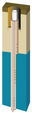
Figure 8-1 shows an example of how the bundled tubes (small brown tubes surrounding a larger diameter tube) are attached to a rigid core tube (larger diameter white tube). The bottoms of the tubes are slotted or perforated and typically surrounded by a fine nylon mesh.
Reminder: Figure 8-1 is for illustrative purposes only and does not necessarily represent full compliance with requirements found in the Wells Regulation.
Casing and Well Screen Requirements
The flexible or rigid tubes support the sides of the well. As such, each tube is considered “casing” under the Wells Regulation. The slotted or perforated end of each tube filter out particulate matter and form the water intake zone. As such, each slotted or perforated end of each tube is considered “well screen” under the Wells Regulation.
The casing requirements and exemptions of the Wells Regulation that are outlined in the “Plainly Stated” section of Chapter 6: Constructing the Hole, Casing & Covering the Test Hole or Dewatering Well apply to the flexible or rigid plastic tubing (casing) and a permanent outer casing that is placed around the bundle of tubes.
The well screen requirements and exemptions of the Wells Regulation that are outlined in the “Plainly Stated” section of Chapter 6: Constructing the Hole, Casing & Covering the Test Hole or Dewatering Well apply to the perforated or slotted area of each tube (well screen).
Reminder: The exemptions in the Wells Regulation allow a person to construct a bundled multi-level system to obtain groundwater samples.
The Wells Regulation - If the new bundled multi-level test hole is finished above the ground surface, the minimum casing extent and casing height requirements in the Wells Regulation that are outlined in Chapter 9: Completing the Test Hole or Dewatering Well Structure apply to each flexible or rigid tube (casing).
For example, if the hole was constructed using sonic equipment, the person constructing the well must ensure each flexible or rigid tube (casing) extends:
- from the water intake zone,
- to at least 40 cm (16 inches) above the highest point on the ground surface within 3 m (10 feet) radially from the outside of the casing after the ground surface (surface drainage) so that water will not collect or pond near the well, as measured on completion of the well’s structural stage.
The Wells Regulation - If the new bundled multi-level system test hole is located in an area where there is a likelihood for pedestrian or vehicular traffic, the Wells Regulation allows for the top of the tubes (casings) to be finished below the ground surface as long as the person constructing the well completes the well with a flush- mounted well cover and meets the Wells Regulation. See Chapter 9: Completing the Test Hole or Dewatering Well Structure for further information on flush-mounted well covers. See Chapter 12: Equipment Installation for further information on flush-mounted well pit (vault) construction requirements.
The Wells Regulation - The top of the tubes (casings) must be covered or capped in accordance with the Wells Regulation requirements. See the “Plainly Stated” section in Chapter 12: Equipment Installation for further information.
Records of Site Condition Regulation - Starting on July 1, 2011, amendments to O. Reg. 153/04 came into force and apply to phase two environmental site assessments (ESAs) conducted in support of records of site conditions (RSCs). For any such RSC submitted on or after this date, where a groundwater sampling method is to be used to characterize contamination or determine if the concentration of a contaminant is above, at or below and applicable site condition standard or standard specified in a risk assessment for the contaminant, the following requirements apply to construction of a well:
- where a monitoring well is being used, well screens shall not exceed 3.1 m (10 feet) in length, based on the saturated length of the screen, and
- where petroleum hydrocarbons or light non-aqueous phase liquids may be present on, in or under a phase two property, sampling depth intervals, including screened intervals of monitoring wells, shall be positioned to intersect the water table.
Implications for the Qualified Person
The qualified person shall ensure that the phase two ESA is conducted in accordance with requirements stated above.
Records of Site Condition Regulation - Please refer to O. Reg. 153/04 for RSC requirements.
Reminder: For clarification of the term “monitoring well” and “qualified person” as they relate to O. Reg. 153/04, see Chapter 2: Definitions & Clarifications, Table 2-2.
Best Management Practice – Designing and Constructing Outer Casings for Bundled Multi-Level Monitoring Test Holes
In addition to the Wells Regulation requirements, the person constructing the bundled multi-level monitoring test hole should consider designing and constructing any permanent outer casing to the recommendations found in the following best management practices of the “Casing” section in Chapter 6: Constructing the Hole, Casing & Covering the Test Hole or Dewatering Well titled:
- “Best Management Practices – Cleaning Casing,”
- “Best Management Practices – Centering the Casing,”
- “Best Management Practices – Joining Sections of PVC Casing,” and
- “Best Management Practices – Casing Seated and Sealed into Bedrock.”
Reminder: There are many factors that affect the casing selection including depth of the well and water quality.
Reminder: Some materials such as ABS, polytetrafluoroethylene (PTFE) (e.g., Teflon), fiberglass and glass are not typically used for casing for test holes. It is important to refer to manufacturer’s specifications and other information to determine if the material is appropriate for use in the test hole at a specific site.
Reminder: A downhole video camera should be used to visually observe the casing, casing joints and the sealing of the bottom of the casing into competent bedrock as long as a contaminant will not interfere with the device.
Annular Space Requirements - Operating Not Later Than 180 Days
This section applies to a new test hole that is scheduled to be abandoned not later than 180 days after the completion of the structural stage of the test hole, and where an outer permanent casing is not placed around the bundle of tubes.
The Wells Regulation - Instead of following the annular space requirements listed in Chapter 7: Annular Space and Sealing, the person constructing a new multi-level monitoring test hole without a permanent outer casing must ensure that:
- there is no movement of water, natural gas, contaminants or other material between subsurface formations or between a subsurface formation and the ground surface in any annular space along a well casing or between overlapping casings, and
- the test hole is scheduled to be abandoned within 180 days of the completion of its structural stage.
Records of Site Condition Regulation - Starting on July 1, 2011, O. Reg. 153/04 prescribes that the provisions of the Ontario Water Resources Act and of Regulation 903 of the Revised Regulations of Ontario, 1990 (Wells) made under that Act, that would apply to a test hole but for section 1.1, and subsections 13 (2), 14.1 (2), 14.2 (3), 14.3 (2), 14.4 (4) and 14.5 (3) of that regulation, apply to a monitoring well installed for the purpose of,
- a phase one environmental site assessment; and
- a phase two environmental site assessment.
Implications for the Qualified Person
The qualified person shall ensure that phase one and phase two environmental site assessments (ESAs) are conducted in accordance with O. Reg. 153/04.
Implications for Annular Space Size and Filling for New Test Holes
With respect to annular space size and filling, the above requirement in O. Reg. 153/04 means that, if the new bundled multi-level monitoring test hole is constructed and is scheduled to be abandoned not later than 180 days after the completion of its structural stage, and is to be used as a monitoring well in an ESA for a record of site condition, then:
- the annular space size and filling exemptions for a test hole stated in this section do not apply, and
- the annular space size and filling requirements for a test hole stated in the section titled “Annular Space – Operating Longer than 180 Days” section do apply regardless of the amount of time that the monitoring well will be in operation.
Reminder: The above requirements in the O. Reg. 153/04 also affect other obligations such as shallow works, casing material and annular space filling for monitoring wells. See Chapter 3: Exemptions: Wells, Activities & Experienced Professionals, Chapter 6: Constructing the Hole, Casing & Covering the Test Hole or Dewatering Well and Chapter 7: Annular Space & Sealing for further information.
Reminder: Please refer to O. Reg. 153/04 for RSC requirements.
Best Management Practice – Sealing Bundled Multi-Level Test Holes
The person constructing a bundled multi-level monitoring test hole should install suitable sealant in the upper portion of the test hole from a depth that is slightly above the level of the upper well screen (slot or perforation on the tube) to the ground surface. The suitable sealant should create a seal between the tubes to the side of the test hole. The person constructing the test hole should follow the best management practices in Chapter 7: Annular Space & Sealing when designing and placing the suitable sealant in the hole.
In addition, the suitable sealant should be designed to seal between all of the tubes and the side of the test hole.
Using sealant that meets the definition of “suitable sealant” in the annular space above the collapsed zone around the well screens ensures that the material is compatible with the quality of the water and reduces the risk of the well acting as a pathway for surface water and other foreign materials to enter groundwater.
Best Management Practice – Using Bundled Multi-Level Test Holes Where Low Vertical Gradients Exist
The person constructing the well should not install a bundled multi-level monitoring test hole where vertical gradients exist that could cause intermingling and biased results. For further information, see the “Best Management Practice – Understanding the Environment prior to the Installation of a Bundled Multi-Level Test Hole” on page 21 of this section.
Best Management Practice–Written Contract for Wells Scheduled to be Abandoned
The person constructing a test hole or dewatering well should have a signed written contract with the well purchaser and the owner of the land, if not the same as the well purchaser, that indicates the well owner has agreed to abandon the well in accordance with the Wells Regulation not later than 180 days after the completion of the structural stage of the test hole or dewatering well. The written contract will help protect the interests of the person constructing the well if the completed test hole or dewatering well is not abandoned within 180 days and the contract will advise the well owner of this scheduling requirement.
Annular Space - Operating Later Than 180 Days
The Wells Regulation allows for the construction of a new bundled multi-level monitoring test hole that will be in operation for more than 180 days after the completion of the well’s structural stage, if the following casing and annular space requirements are met:
The Wells Regulation - The person constructing the well must install a permanent outer casing around the bundle of tubes, which are considered inner casings.
The Wells Regulation - Depending on the type of well construction method used, the person constructing the well must follow the Wells Regulation requirements listed in Chapter 7: Annular Space & Sealing, Table 7-1 A and Table 7-1B to create and seal an annular space on the outside of the outer permanent casing.
Reminder: As a necessary modification for systems installed using drilling, augering or sonic equipment, the depth of the annular space must extend from the ground surface to at least the bottom of the permanent outer casing or 6 m (19.7′), whichever is less.
The Wells Regulation - When the bundle of smaller diameter casings (e.g., flexible or rigid plastic tubing) is installed into the permanent outer casing, the annular space between the permanent outer casing and the inner casings (or tubes) must be sealed with a suitable sealant to prevent the entry of surface water and other foreign materials into the well. Depending on the environment, a suitable sealant could include a bentonite product, cement product or a mechanical device such as a packer.
The Wells Regulation - If any groundwater is entering the annular space between the bundle of tubes (casings) and the permanent outer casing, the entire annular space from the tubes to the permanent outer casing must be sealed, with necessary modifications, in accordance to the minimum requirements of Chapter 7: Annular Space & Sealing, Table 7-1 A and Table 7-1B. The annular space between casings of a well constructed by the use of a driven point is not required to be sealed in accordance with Chapter 7: Annular Space & Sealing, but is required to be sealed with a suitable sealant.
The installation of an inner and a permanent outer casing is referred to as a double walled casing in the Wells Regulation.
Although a person constructing a well is not specifically required to seal around the casings or tubes between wells screens in a bundled multi-level monitoring test hole below the permanent outer casing, the person must do what is necessary as the Ontario Water Resources Act prohibits every person from discharging or causing or permitting the discharge of any material of any kind into any waters that may impair the quality of any waters. This includes prohibiting contaminated groundwater from impairing the quality of other groundwater zones when constructing a well.
The regulatory exemptions regarding sealing the annular space below the permanent outer casing allow for well technicians, engineers and geoscientists to use their professional expertise to design and install a bundled system on a case by case basis, thereby enabling the testing and sampling of various groundwater intervals while preventing (further) contamination.
Persons using the above professional judgement and the well owner should be aware of the following requirement.
The Wells Regulation - If the test hole or dewatering well acts as a pathway for the movement of:
- natural gas,
- contaminants, or
- other materials
between subsurface formations (including aquifers) or between the ground surface and a subsurface formation and where the movement may impair the quality of the any waters, the person abandoning the well, often the well owner, must do one of the following:
- take measures to prevent the movement of the above materials and ensure the measures are functional at all times, or
- immediately abandon the well.
This Wells Regulation requirement ensures that, at all times, steps must be taken by the well owner to prevent the well from acting as a pathway for contaminants that may impair groundwater resources.
Reminder - Further information on abandonment requirements is provided in Chapter 16: Abandonment: When to Plug & Seal Test Holes and Dewatering Wells and Chapter 17: Abandonment: How to Plug & Seal Test Holes & Dewatering Wells of this manual.
Examples
The following provides two examples of the annular space requirements for new bundled multi-level monitoring test holes that will be in operation more than 180 days:
Example A: Constructing a Bundled Multi-level Monitoring Test Hole with Seals using Direct Push Equipment
A person constructing a bundled multi-level monitoring test hole uses direct push equipment to advance a hole in the ground by the use of a driven point. The person constructing the test hole completes the well in the following manner:
- A permanent outer casing is driven with a driven point to the full depth of the hole to create the hole and keep it open.
- The bundle of flexible or rigid plastic tubes is installed into the hole to the designed depths.
- The permanent outer casing, used to hold the hole open, is lifted up exposing all well screens (or slots) in the bundle. The driven point used during the construction of the hole is left in the ground below the bundle of tubes. The formation should collapse around the bundle below the outer casing.
- As required by the Wells Regulation, the permanent outer casing remains in the test hole. As a best management practice, the permanent outer casing is installed to a depth above the top of the upper well screen (see best management practice following the examples in this section).
- As required by the Wells Regulation, any annular space around the permanent outer casing is sealed to prevent the movement of water, natural gas, contaminants or other material between subsurface formations or between a subsurface formation and the ground surface.
- As required by the Wells Regulation, the annular space between the bundle of flexible or rigid tubes and the permanent outer casing is sealed with a suitable sealant, such as a bentonite product, a cement product or a mechanical device (e.g., packer), to prevent the entry of surface water and other foreign materials into the well (see the second best management practice on page 19 of this chapter).
Example B: Constructing a Bundled Multi-level Monitoring Test Hole using Dual Roatary Equipment
A person constructing a bundled multi-level monitoring test hole uses dual rotary (barber) equipment to advance a hole in the ground. The person constructing the test hole completes the well in the following manner:
- As required by the Wells Regulation, a hole that is at least 5.1 cm (2″) larger than the outside diameter of the permanent outer casing is advanced from the ground surface to at least the designed bottom of the permanent outer casing. A temporary outer casing that is the same size as the hole is advanced during the drilling process.
- As required by the Wells Regulation, a permanent outer casing with centralizers is installed into the hole and positioned to be located above all well screens in the bundle.
- A hole is drilled below the permanent outer casing to the designed depth of the hole. A temporary inner casing is installed during drilling to the full depth of the hole to keep the hole open. The drilling tools are removed from the hole.
- A bundle of flexible or rigid plastic tubes is installed into the hole to the designed depths.
- The temporary inner casing, used to hold the hole open, is lifted up and out of the hole allowing all of the well screens in the bundle to be exposed to the formation. The formation should collapse around the bundle below the permanent outer casing.
- As required by the Wells Regulation, the annular space between the permanent outer casing and temporary outer casing is filled with suitable sealant using a tremie pipe. The temporary casing is used as the tremie pipe. As an alternative, a small diameter tremie pipe can be installed in the annular space to place the suitable sealant (see Chapter 7: Annular Space & Sealing for further information). As required by the Wells Regulation, the tremie pipe is immersed in the rising accumulation of the suitable sealant. The suitable sealant must prevent the movement of water, natural gas, contaminants or other material between a subsurface formation and the ground surface. The temporary outer casing is then removed.
- As required by the Wells Regulation, the annular space between the permanent outer casing and temporary outer casing is filled with suitable sealant using a tremie pipe. The temporary casing is used as the tremie pipe. As an alternative, a small diameter tremie pipe can be installed in the annular space to place the suitable sealant (see Chapter 7: Annular Space & Sealing for further information). As required by the Wells Regulation, the tremie pipe is immersed in the rising accumulation of the suitable sealant. The suitable sealant must prevent the movement of water, natural gas, contaminants or other material between a subsurface formation and the ground surface. The temporary outer casing is then removed.
Best Management Practice – Length and Sealing of Permanent Outer Casing for a Bundled Multi-Level Monitoring Test Holes
The permanent outer casing should extend to at least 6 m (19.7′) from the ground surface or as close to the top of the upper screened interval as possible. The outer casing material and installation should follow the requirements, best management practices and notes found in Chapter 6: Constructing the Hole, Casing & Covering the Test Hole or Dewatering Well. The annular space size and depth along the outside of the outer permanent casing should be created and sealed using the best management practices found in Chapter 7: Annular Space & Sealing.
Increasing the length of the outer casing and properly sealing an annular space reduces the risk of a pathway being created for surface water, contaminants and other foreign materials to move from the ground surface into the groundwater. Eliminating a pathway that allows surface water, contaminants or other foreign materials:
- increases the quality assurance that samples are representative of the groundwater, and
- decreases the risk of impairment to the groundwater resource from surface sources of contaminants.
Best Management Practice – Sealing the Annular Space around the Inner Casings for a Bundled Multi-Level Monitoring Test Hole
Even if groundwater has not been observed between the casings of a bundled multi-level monitoring test hole, the entire annular space between the plastic tubes and the permanent outer casing should be sealed with a suitable sealant. The suitable sealant should be installed using a tremie pipe from the bottom of the outer casing to the ground surface. The tremie pipe should be immersed in the rising accumulation of the suitable sealant. The suitable sealant should prevent the movement of water, natural gas, contaminants or other material between subsurface formations and between a subsurface formation and the ground surface.
Installing a proper suitable sealant in the entire annular space between casings reduces the risk of a pathway being created for surface water, contaminants and other foreign materials to move from the ground surface into groundwater resources. Eliminating such pathways that allow surface water, contaminants or other foreign materials:
- increases the quality assurance that samples are representative of the groundwater, and
- decreases the risk of impairment to the groundwater resource from surface sources of contaminants.
Best Management Practice – Sealing a Bundled Multi-Level Monitoring Test Hole Constructed by the Use of a Driven Point
When groundwater is observed leaking into the annular space amongst the plastic tubes and the permanent outer casing of a bundled multi-level monitoring test hole constructed by the use of a driven point (described in example “A” on page 17 of this chapter), a suitable sealant should be placed into this entire annular space. The suitable sealant should be installed using a tremie pipe from the bottom of the outer casing to the ground surface. The tremie pipe should be immersed in the rising accumulation of the suitable sealant. The suitable sealant should prevent the movement of water, natural gas, contaminants or other material between subsurface formations and between a subsurface formation and the ground surface.
Installing a properly sealed annular space between casings reduces the risk of a pathway being created for surface water, contaminants and other foreign materials to move between subsurface formations and from the ground surface into groundwater resources. Eliminating such pathways that allow surface water, contaminants or other foreign materials:
- increases the quality assurance that samples are representative of the groundwater, and
- decreases the risk of impairment to the groundwater resource from surface sources of contaminants.
Recommended Environment For A Bundled Multi-Level System
The bundled system’s tubes of varying lengths can work well in identifying the vertical extent of a contaminant plume in a collapsing formation (e.g. a sand formation) that has a small vertical hydraulic gradient.
These systems, however, are not suitable in some environments and for certain activities. For example, the bundled multi-level test hole system’s small diameter tubing makes measuring the hydraulic head difficult or in some cases impossible. In some environments, a suitable sealant (e.g. cement, bentonite, packer) is needed around casings and between the depths of individual well screens to prevent intermingling of the groundwater and contaminants in the groundwater. As such, it is not advisable to use a bundled multi-level monitoring test hole to determine the vertical extent of the plume in a number of environments including formations that:
- do not collapse, or
- have vertical hydraulic gradients between formations or within the groundwater zone that could cause intermingling or sample bias.
Best Management Practice – Understanding the Environment prior to the Installation of a Bundled Multi-Level Test Hole
To prevent vertical movement of contaminants or groundwater between well screens, it is important for the person constructing the well and the Professional Geoscientist or Professional Engineer to ensure background information and formation samples confirm that the formation will fully collapse around the bundles of tubing and that vertical hydraulic gradients are not present. If annular spaces are created due to material not fully collapsing around the bundles of tubing or vertical hydraulic gradients are present after the bundled system is installed, clean and contaminated groundwater could mix with one another at the different well screen intervals and cause groundwater impairment or a bias in sampling results
Nested Multi-Level Monitoring Test Holes With Seals
Nested multi-level monitoring test holes with seals are designed to study groundwater at different depths in a formation or in various formations.
A common design will have three or four PVC plastic or stainless steel casings (risers) installed into a hole. A manufactured PVC plastic or stainless steel well screen is attached to the bottom of each casing. A typical riser has an inside diameter range from 2.5 cm (1″) to 5 cm (2″). The length of each casing is designed to allow the well screen to be set to a discrete depth in the ground. Well screens are usually no longer than 0.3 m (1′) to 0.6 m (2′).
Installation commonly occurs as follows:
- A hole is constructed into a formation or formations using auger, sonic or rotary drilling equipment. The hole should be large enough to install the number of casings needed. Measurements and observations should be made about the location of the formation, location of groundwater levels and aquifer sampling zones when the well construction equipment is being advanced into the ground.
- A temporary drill rod or starter casing may be installed during the construction of the hole in case a portion of the formation is prone to collapse or to prevent the vertical movement of groundwater and contaminants.
- Based on observations, the longest casing and well screen are installed into the hole to the deepest identified sampling location.
- Inert sand is placed in the annular space of the hole, typically using a tremie pipe, to create a filter pack around the deepest well screen.
- A bentonite or cement based sealant is placed in the annular space from the filter pack up to almost the next sampling interval.
- The next casing and well screen are installed into the hole, and the filter pack and sealing process is repeated.
- The process is continued until the hole is completely filled.
Each well screen allows for collection of a groundwater sample from a discrete zone in the formation and allows for the measurement of groundwater levels and for hydraulic conductivity testing. If enough screen points are installed at the correct locations, the vertical delineation of a contaminant plume can then be determined.
Figure 8-2 below shows an illustration of the steps involved in creating a nested multi-level test hole with seals
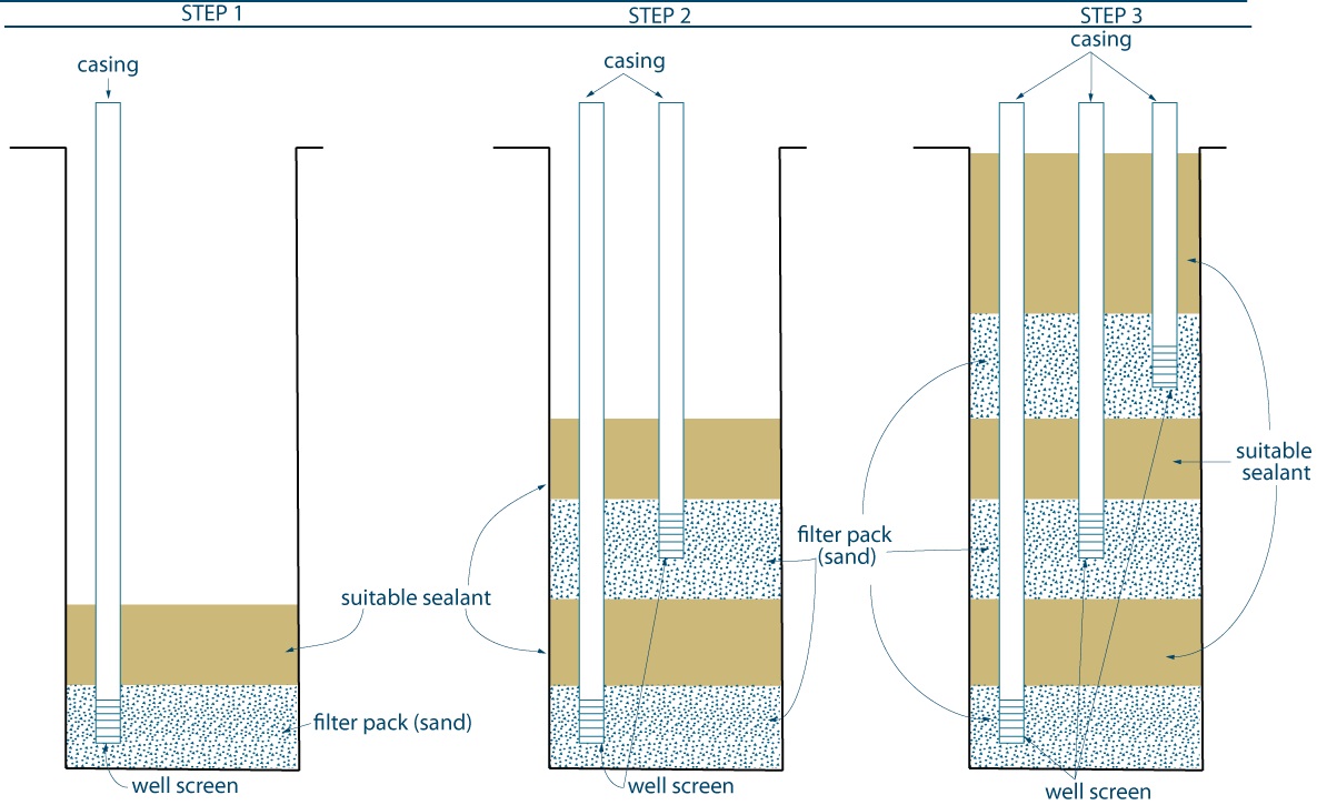
The three steps shown in Figure 8-2 illustrate a common way to install the components of a nested multi-level test hole with seals. Step 1 shows a well screen and casing placed into the test hole. Inert sand is placed around the well screen to create a filter pack. Suitable sealant is placed above the filter pack. The process is repeated until the hole is completely filled as shown in Step 3.
Reminder - Figure 8-2 is for illustrative purposes only and does not necessarily represent full compliance with requirements found in the Wells Regulation.
Casing And Well Screen Requirements
Casing material may be plastic, stainless steel, polytetrafluoroethylene or fiberglass. The multiple casings (risers) that are installed support the sides of the well. As such, each casing is considered “casing” under the Wells Regulation. The manufactured well screens attached to the bottom of the casings meet the definition of the term “well screen” under the Wells Regulation.
The casing and well screen requirements and exemptions discussed in the “Casing and Well Screen Requirements” section for a bundled multi-level monitoring test hole on page 10 of this chapter apply to a nested multi-level test hole with seals.
Best Management Practice - Designing and Constructing Casings and Well Screens for Nested Multi-Level Monitoring Test Holes with Seals
The person constructing the nested multi-level monitoring test hole should consider designing and constructing any casing and well screen to the recommendations found in the following best management practices of the “Casing” and “Test Hole & Dewatering Well Screens” sections in Chapter 6: Constructing the Hole, Casing & Covering the Test Hole or Dewatering Well titled:
- “Best Management Practice – Cleaning Casing,”
- “Best Management Practice – Centering the Casing,”
- “Best Management Practice – Joining Sections of PVC Casing,”
- “Best Management Practice – Seating and Sealing Casing Into Bedrock,”
- “Best Management Practice – Cleaning Well Screens,”
- “Best Management Practice – Using Clean Pre-Packaged Well Screens,”
- “Best Management Practice – Using New Well Screens,”
- “Best Management Practice – Designing a Well Screen,”
- “Best Management Practice – Determining Well Screen Slot Size, Length and Target Depth for Test Holes or Dewatering Wells,” and
- “Best Management Practice – Designing a Well Screen for Drilled Wells to Achieve a Sand-Free State.”
Reminder: There are many factors that affect the casing selection including depth of the well and water quality.
Reminder: Some materials such as acrylonitrile-butadiene-styrene (ABS), polytetrafluoroethylene (PTFE) (e.g. Teflon), fiberglass and glass are not typically used for casing for test holes. It is important to refer to manufacturer’s specifications and other information to determine if the material is appropriate for use in test holes at a specific site.
Reminder: A downhole video camera should be used to visually observe the casing, casing joints, the seal between the screen and casing as long as a contaminant will not interfere with the device.
Annular Space - Operating Not Later Than 180 Days
For this circumstance, the requirements for the size and filling of the annular space in the Wells Regulation and in the Records of Site Condition regulation for a nested multi-level monitoring test hole with seals are outlined in the “Annular Space Requirements - Operating not Later than 180 Days” section for a bundled multi-level monitoring test hole on page 13. Relevant best management practices are also found in this section starting on page 13.
Annular Space - Operating Later Than 180 Days
The Wells Regulation allows for the construction of a new nested multi-level monitoring test hole with seals that will be in operation for more than 180 days after the completion of the well’s structural stage, if the following casing and annular space requirements are met:
The Wells Regulation - The person constructing the test hole must install a permanent outer casing around the inner casings.
The Wells Regulation - Depending on the type of well construction method used, the person constructing the well must follow the Wells Regulation requirements listed in Chapter 7: Annular Space & Sealing, Table 7-1 A and Table 7-1B to create and seal an annular space on the outside of the permanent outer casing.
Reminder: As a necessary modification for systems installed using drilling, augering or sonic equipment, the depth of the annular space must extend from the ground surface to at least the bottom of the permanent outer casing or 6 m (19.7′), whichever is less.
The Wells Regulation - When the smaller diameter casings (e.g., PVC plastic) are installed into the permanent outer casing, the annular space between the permanent outer casing and inner casings must be sealed with a suitable sealant to prevent the entry of surface water and other foreign materials into the well. Depending on the environment, a suitable sealant could include a bentonite product, a cement product or a mechanical device such as a packer.
The Wells Regulation - If any groundwater is entering the annular space between the permanent outer casing and the inner casings, the entire annular space between the inner casings and permanent outer casing must be sealed, with necessary modifications, in accordance to the minimum requirements of Chapter 7: Annular Space & Sealing, Table 7-1 A and Table 7-1B. The annular space between casings of a well constructed by the use of a driven point is not required to be sealed in accordance with Chapter 7: Annular Space & Sealing, but is required to be sealed with a suitable sealant.
The installation of an inner and permanent outer casing is referred to as a double walled casing in the Wells Regulation.
Although a person constructing a well is not specifically required to seal around the inner casings between well screens in a nested multi-level monitoring test hole below the permanent outer casing; the person must do what is necessary as the Ontario Water Resources Act prohibits every person from discharging or causing or permitting the discharge of any material of any kind into any waters that may impair the quality of any waters. This includes prohibiting contaminated groundwater from impairing the quality of other groundwater zones when constructing a well.
The regulatory exemptions regarding sealing the annular space below the permanent outer casing allow for well technicians, engineers and geoscientists to use their professional expertise to design and install a bundled system on a case by case basis, thereby enabling the testing and sampling of various groundwater intervals while preventing (further) contamination.
Persons using the above professional judgement and the well owner should be aware of the following requirement.
The Wells Regulation - If the test hole or dewatering well acts as a pathway for the movement of:
- natural gas,
- contaminants, or
- other materials
between subsurface formations (including aquifers) or between the ground surface and a subsurface formation and where the movement may impair the quality of the any waters, the person abandoning the well, often the well owner, must do one of the following:
- take measures to prevent the movement of the above materials and ensure the measures are functional at all times, or
- immediately abandon the well.
This Wells Regulation requirement ensures that, at all times, steps must be taken by the well owner to prevent the well from acting as a pathway for contaminants that may impair groundwater resources.
Reminder: Further information on abandonment requirements is provided in Chapter 16: Abandonment: When to Plug & Seal Test Holes & Dewatering Wells and Chapter 17: Abandonment: How to Plug & Seal Test Holes & Dewatering Wells of this manual.
Examples
The following provides two examples of the well construction requirements for new nested multi-level monitoring test holes with seals that will be in operation more than 180 days.
Example A: Constructing a Nested Multi-level Monitoring Test Hole with Seals using Auger Equipment
A person constructing a nested multi-level monitoring test hole with seals uses auger equipment to advance a hole in the ground. The person constructing the test hole completes the well in the following manner:
- A hole, that must be at least 7.6 cm (3″) larger than the outside diameter of the permanent outer casing, is advanced to a predetermined depth using hollow stem auger flights. The auger flights act as a temporary casing during the construction process.
- The longest casing and well screen are installed into the hole to the deepest identified sampling zone. Using the best management practices outlined in Chapter 6: Constructing the Hole, Casing & Covering the Test Hole or Dewatering Well, inert sand is carefully placed in the annular space of the hole to create a filter pack around the well screen. Using the best management practices found in Chapter 7: Annular Space & Sealing, bentonite or a cement based suitable sealant is placed in the annular space from the filter pack up to almost the next sampling interval.
- The auger flights, temporarily used to hold the hole open, are lifted up exposing the well screen and filled annular space to almost the next interval. Measurements are performed to verify that the annular space materials have filled any annular space occupied by the auger flights. The next casing and well screen are installed into the hole and the best management practices of placing the filter pack and suitable sealant are repeated.
- The shortest casing and final well screen are installed in the hole and the best management practices of placing the filter pack around the shallowest well screen are repeated.
- A permanent outer casing is installed into the test hole. The permanent outer casing should be installed to a depth above the top of the shallowest well screen.
- As required by the Wells Regulation, the annular space around the permanent outer casing and auger flights is filled with suitable sealant using a tremie pipe. The auger flights are used as the tremie pipe to place the suitable sealant. As an alternative, a small diameter tremie pipe can be installed in the annular space to place the suitable sealant (see Chapter 7: Annular Space & Sealing for further information). As required by the Wells Regulation, the tremie pipe is immersed in the rising accumulation of the suitable sealant. The suitable sealant must prevent the movement of water, natural gas, contaminants or other material between a subsurface formation and the ground surface. The temporary auger flights (temporary outer casing) are then removed.
- As required by the Wells Regulation, the annular space between the permanent outer casing and the inner casings is sealed with a suitable sealant such as a bentonite product, a cement product or a mechanical device such as a packer to prevent the entry of surface water and other foreign materials into the well. In addition, if groundwater is leaking into the annular space between the inner casings and the permanent outer casing, a suitable sealant must be installed in the same manner as step 6 of this example.
Example B: Constructing a Nested Multi-level Monitoring Test Hole with Seals using Sonic Drilling Equipment
A person constructing a nested multi-level monitoring test hole with seals uses sonic drilling equipment to advance a hole in the ground. The person constructing the test hole completes the well in the following manner:
- As required by the Wells Regulation, a hole, that is at least 7.6 cm (3″) larger than the outside diameter of the permanent outer casing, is advanced from ground surface to at least the predetermined bottom of the permanent outer casing. A temporary outer casing that is the same size as the hole is advanced during the drilling process.
- A smaller diameter hole is drilled below the temporary outer casing to the predetermined depth of the hole. A permanent outer casing that is the same size as the smaller hole is temporarily advanced during the drilling process to the full depth of the hole. The permanent outer casing temporarily keeps the hole open. The drilling tools are removed from the hole.
- The longest casing and well screen are installed into the hole to the deepest identified sampling zone. Using the best management practices outlined in Chapter 6: Constructing the Hole, Casing & Covering the Test Hole or Dewatering Well, inert sand is carefully placed in the annular space of the hole to create a filter pack around the well screen. Using the best management practices found in Chapter 7: Annular Space & Sealing, a bentonite or a cement based suitable sealant is placed in the annular space from the filter pack up to almost the next sampling interval.
- The permanent outer casing, temporarily used to hold the hole open, is lifted up exposing the well screen and filled annular space to almost the next interval. The next casing and well screen are installed into the hole and the best management practices to place filter pack and suitable sealant are repeated.
- The shortest casing and final well screen are installed in the hole and the best management practices of placing the filter pack around the shallowest well screen are repeated. The permanent outer casing is raised to a pre-determined depth above the shallowest well screen but below the top of the filter pack.
- As required by the Wells Regulation, the annular space around the permanent outer casing and temporary outer casing is filled with suitable sealant using a tremie pipe. The temporary casing is used as the tremie pipe to place the suitable sealant. As an alternative, a small diameter tremie pipe can be installed in the annular space to place the suitable sealant (see Chapter 7: Annular Space & Sealing for further information). As required by the Wells Regulation, the tremie pipe is immersed in the rising accumulation of the suitable sealant. The suitable sealant must prevent the movement of water, natural gas, contaminants or other material between a subsurface formation and the ground surface. The temporary outer casing is then removed.
- As required by the Wells Regulation, the annular space between the permanent outer casing and the inner casings is sealed with a suitable sealant, such as a bentonite product, a cement product or a mechanical device such as a packer, to prevent the entry of surface water and other foreign materials into the well. In addition, if groundwater is leaking into the annular space between the inner casings and the permanent outer casing, a suitable sealant must be installed in the same manner as Step 6 of this example.
Annular Space - Best Management Practices
Best Management Practice – Sealing Outer Casing and Between Inner and Outer Casings
The person constructing the nested multi-level monitoring test hole with seals should consider the sealing recommendations around the permanent outer casing and between casings found in:
- “Best Management Practice – Length and Sealing of Permanent Outer Casing for a Bundled Multi Level Monitoring Test Hole” on page 19 of this chapter
- “Best Management Practice – Sealing the Annular Space around the Inner Casings for a Bundled Multi-Level Monitoring Test Hole” on page 19 of this chapter
- “Best Management Practice – Sealing a Bundled Multi-Level Monitoring Test Hole Constructed by the Use of a Driven Point” on page 20 of this chapter
Best Management Practice – Installing Temporary Casing to Bottom of Hole in Overburden Formations
When constructing a hole through a potential contaminant plume in unconsolidated and consolidated formations, a temporary casing that is the size of the hole should be advanced during the construction process. The temporary casing reduces the risk of the vertical migration of contaminants in the hole during the installation of casing and the sealing of the test hole
Best Management Practice – Installing Nested Multi-Level Systems with Seals Immediately after Creating the Hole
When constructing a hole through a contaminant plume, the person constructing the well should install the nested multi-level monitoring system within the hole and seal the areas as quickly as possible to reduce the risk of the vertical migration of contaminants between groundwater zones.
Proper well development, purging, water sampling and interpretation of the parameters should be immediately undertaken to verify that the well construction has not allowed for the migration of contaminants or, if contaminants have migrated, a well repair or proper abandonment of the well occurs.
Best Management Practice – Determining the Size of Hole and Using Centralizers and Centering Discs in Nested Multi-Level Systems
The construction and installation techniques for nested multi-level systems make it difficult to centre and separate casings in a hole. If casings are touching the side of the hole or each other, sections of the hole may not be properly sealed, creating void spaces once the suitable sealant or filter pack has been placed into the test hole. The voids can create vertical migration pathways for contaminants or groundwater to mix together. To reduce the risk of voids and allow for the proper placement of filter packs and suitable sealant, the person constructing the well should:
- create an initial hole that is large enough to provide sufficient space:
- between casings,
- between the casings and the side of the test hole, and
- to allow for the installation of a tremie pipe,
- install lantern style centralizers with centering discs that separate the casings from one another and the side of the hole while offering a space for a tremie pipe (see Figure 8-3).
- install centralizers and discs near the top of the hole, below a well screen and at intervals of about 10 m (33′) between each location of the centralizers and disks.
Figure 8-3: Lantern Style Centralizer With Discs
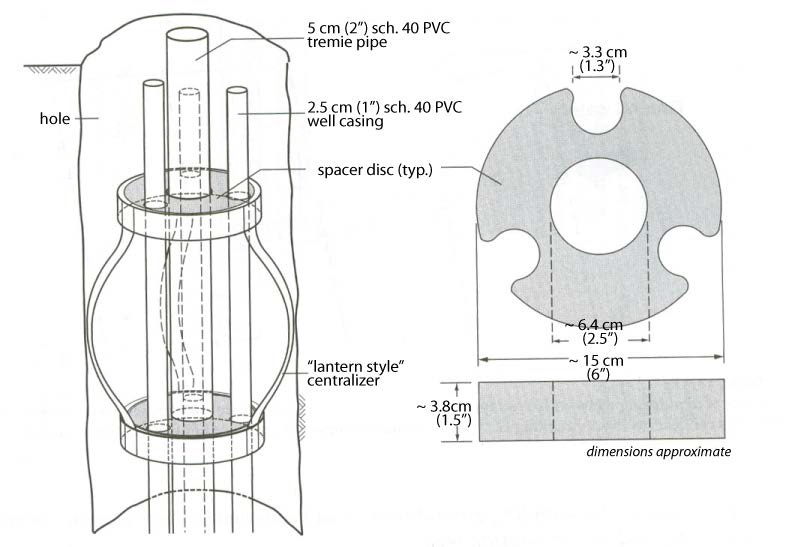
The left side of Figure 8-3 shows a cross section of the drill hole with a lantern style centralizer placed inside the hole. The centralizer is centering the casing in the hole so that is does not touch the side of the hole or other casing inside the hole by using a spacer disc that each casing runs through.
The right side of Figure 8-3 shows a top down view of the centralizer inside the hole with the holes in the spacer disc that casing pipes go in to separate the casing from each other and the side of the hole.
Best Management Practice – Filter Packs in Nested Multi-level Systems
In addition to the Wells Regulation requirements, the best management practices and information found in the section titled “Filter Packs around Well Screens for Drilled Test Holes or Dewatering Wells” of Chapter 6: Constructing the Hole, Casing & Covering the Test Hole or Dewatering Well should be used to ensure the filter pack and secondary filter pack material:
- are inert,
- represent the best hydraulic conditions for sampling groundwater and measuring aquifer characteristics, and
- are properly placed around the well screen.
Best Management Practice – Designing and Placing Sealant in Nested Multi-Level Systems
In addition to the Wells Regulation requirements, the person constructing the test hole should install a suitable sealant between filter packs and in the upper portion of the test hole and should follow the best management practices in Chapter 7: Annular Space & Sealing when determining the type of suitable sealant and when placing suitable sealant in the hole. Proper use and placement of a suitable sealant in the test hole’s annular spaces ensures the material is compatible with the quality of the water and reduces the risk of the well acting as a pathway for surface water and other foreign materials to enter the aquifer.
Dedicated Multi-Level Monitoring Test Holes
Dedicated multi-level monitoring test holes are designed to study groundwater at different depths in a formation or various formations. Where feasible, monitoring at different levels from one well location enhances the understanding of the vertical distribution of contaminants and aquifer hydraulic characteristics.
A typical installation consists of one dedicated multi-level casing system that spans the length of the test hole. Ports (or well screens) are placed at predetermined intervals on the dedicated multi-level casing system. The ports connect to tubes, channels or cables or the interior of the multi-level casing system. Within the dedicated multi-level casing system, the sampling devices, tubing, channels or cables extend from the ports to the ground surface and attach to various sampling pumps or monitoring devices.
For some installations, the annular space along the casing and between the ports of the dedicated multi-level casing system may be sealed with inflatable packers or suitable sealant between the outside of the casing and the side of the well. Depending on the installation, a filter pack may be installed in an annular space beside the ports to the side of the well.
For other installations, multiple outer casing sections and well screens of the same diameter are sealed together (sometimes called a casing and screen string) based on a predetermined design for the hole. The casing and screen string is placed into the well. The annular space intervals along the casing sections and between the well screens are sealed with sealant. A filter pack is placed in the annular space beside the well screens to the side of the well. A smaller diameter dedicated multi-level casing system with ports is placed into the casing and screen string. The depths of the ports will match the elevation of the well screens. Between the ports, the annular space intervals between the system’s casing and outer casing may be sealed with inflatable packers or sealant. Depending on the installation, a filter pack may be installed in an annular space beside the ports to the inner portion of the well screen.
Once packers or suitable sealant are placed, the sampling intervals are typically purged through ports, monitored for stabilization criteria and sampled. The person conducting the monitoring should carefully evaluate geophysical and hydraulic information previously collected from the hole to determine the potential of groundwater and contaminants moving vertically between ports.
See the best management practices starting on page 61 regarding construction and siting of dedicated multi-level monitoring test holes.
Advantages of dedicated multi-level monitoring test holes, compared to other test holes, include:
- Groundwater samples and hydraulic head measurements can be obtained from many more zones than a nested multi-level test hole with seals or a well cluster. More sampling points can provide a more accurate representation of the aquifer and the contaminant plume in the groundwater.
- In many cases, a dedicated multi-level casing system can be placed into the hole instead of a nested multi-level test hole or a series of single-level test holes. A system consisting of one pipe or liner with multiple ports simplifies the process of installing packers or suitable sealant in the hole. As long as the dedicated multi-level casing system is properly centered in the hole, suitable sealant should create a proper seal between sampling ports. If casings are touching the side of the hole or each other in a nested multi-level test hole, sections of the hole may not be properly sealed creating void spaces once the suitable sealant or filter pack has been placed into the test hole.
- Fewer holes need to be advanced into the ground to delineate vertical groundwater characteristics which lowers well construction costs and reduces the footprint on the property. For example, one dedicated multi-level monitoring test hole can do the job of five nested multi-level test holes with seals or 20 single test holes in a well cluster.
- The volume of purged water for sampling is reduced resulting in lower water storage and disposal costs.
- The small diameters of the tubes and channels used in a dedicated system allow groundwater head pressures to equalize more quickly with a result that hydraulic heads (i.e., static water levels) can be measured rapidly.
- Some designs eliminate the need for suitable sealant or backfill material around ports that can impact the sample water quality.
Disadvantages of dedicated multi-level monitoring test holes, compared to other test holes, include:
- The drilling options for installing these systems can be limited.
- The hole may require a temporary (starter) casing to be placed into the hole to reduce the risk of the vertical migration of contaminants and hole collapse.
- Qualified well technicians who are familiar with the type of dedicated system are needed to install the casing, ports and other equipment correctly.
- The installation of vertical isolation packers or suitable sealant in wells requires very reliable material and installation equipment due to the highly complex system.
- If the system fails during or after installation, parts such as specialized packers or ports may not be readily repairable or replaceable.
- Due to their design, certain systems may be difficult to remove making repairs complicated.
- Some dedicated systems can be more difficult to properly abandon (plug and seal).
- If packers are used, the well owner should have a contingency plan in place in case there is a partial or complete failure of a packer.
- Freezing problems can cause inflation line blockages when attempting to re-inflate packers in certain dedicated systems.
- In certain dedicated systems, inflatable packers become unsealed increasing the risk of the vertical migration of contaminants along the well casing or open hole.
- Flowing artesian conditions may create high enough water pressures to prevent the installation of some dedicated systems.
- As with single well installations, improper assembly of electronics may cause pressure transducers and dataloggers to act as sacrificial anodes, and increase the risk of lightening strikes.
- If a liner dedicated system is used (e.g. Water FLUTe™), contaminants can leach from the liner into groundwater that could cause a bias in some samples. For example, Water FLUTe™ liners leach trace levels of toluene for several months.
- Continuous Multi-Channel Tubing (CMT™) tubing could allow for a bias in sample results. Bias can be minimized by purging, using specialized tubing or using systems that take samples from areas of the channel near the ports.
- There is an increased potential for vertical migration of contaminants if packer locations or bentonite seals are not chosen or installed carefully.
There are four dedicated multi-level monitoring systems that are known to be commonly used in Canada at the time of publication. These systems are:
- Schlumberger Westbay© System,
- Solinst Waterloo™ System (since, 1984),
- Solinst CMT™ (Continuous Multi-Channel Tubing™) System (since, 1999), and
- Water FLUTe™ (Flexible Liner Underground Technology) System.
Table 8-1 outlines common characteristics of the systems. Figures 8-4 to 8-21 (pages 41 to 51) show various components of the systems.
Reminder: The use of brand names in this manual is for identification purposes only and does not constitute an endorsement by the Ministry of the Environment.
Reminder: The information and illustrations of these systems do not constitute a recommendation of any or all of the systems. The table and illustrations are presented solely to provide information on the systems that are currently available and how these systems could be installed to meet the requirements of the Wells Regulation.
| Well Characteristics | Westbay® System | Solinst Waterloo™ System | Solinst CMT™ (Continuous Multi-Channel Tubing™) System | Water FLUTe™ (Flexible Liner Underground Technology) System |
|---|---|---|---|---|
| Casing |
This dedicated multi-level casing system features casings with multiple packers and valved ports to seal off and provide selective access to monitoring zones. Components are manufactured from plastic or stainless steel depending on depth, temperature, or other borehole conditions. Tools and instruments are run inside the casing on wireline to locate and operate the ports. The combination of dedicated casing and portable instrumentation provides the ability to take measurements, collect samples, and carry out a range of hydraulic tests from any number of zones in a single borehole. Common systems provide plastic casing in two diameters:
Lengths of casing are joined to other casings, ports or packers using watertight couplings with o-rings and shear rods. The system can be installed in vertical, inclined, or deviated boreholes. |
This system is built on 5 cm (2″) inside diameter PVC casing. Casing lengths are attached to packers, ports, a base plug and surface manifold to form one long string with a 5 cm (2″) inside diameter. In some cases, the casing and other attached components are filled with water. The additional weight of the water allows the casing to sink and stay in the correct place in the hole. The casing is joined to other materials such as ports and packers using a nylon shear wire and an O-ring gasket system. The casing and sampling system is assembled at the well site during installation. |
This system uses custom-extruded flexible 4.3 cm (1.7″) outside diameter multi-channel medium density polyethylene (MDPE) tubing (referred to as Continuous Multi-Channel Tubing™). The MDPE tubing is considered casing. The casing has internal partitions creating a 7-channel honeycomb design in plan view. A smaller casing with a 3-channel design is available when constructing holes using a small diameter direct push system. The smaller casing has an outside diameter of 2.8 cm (1.1″). The MDPE tubing (casing) is stiff while light and flexible enough for ease of handling and installation. Centralizers should be installed at predetermined intervals on the MDPE tube to help centre the tube in the hole. The MDPE tube (casing) comes in bundles that can be unrolled on the ground. The continuous length of tubing (casing) eliminates the need for designing and assembling joints. The MDPE tube (casing) allows for the installation of various probes and tools. |
This system uses an impermeable liner of polyurethane-coated nylon fabric to seal the entire hole isolating up to 20 discrete intervals in a single hole. The liner is considered casing when fully installed. To monitor for leaks, the water level within the liner is measured and compared with the original water level. The liner (sometimes referred to as a “sock”) is about 0.5 mm thick. The liner allows for the rest of the space in the well to be available for sampling and other monitoring systems. A liner must be custom manufactured. In some cases, it can take more than a couple of weeks from the time the liner is ordered until it is installed. Therefore, it is important to properly seal the hole to prevent the entry of surface water, contaminants and other foreign materials as required by the Wells Regulation. The vertical migration of contaminants or groundwater can be prevented by installing a temporary liner without ports. The liner is everted from the shipping reel into the hole using water. The weight of the water placed inside the liner pushes it down the hole and forces it to the sides of the hole. The pressurized liner supports the sides of the well. The liner seals to the sides of the hole and prevents formation material from entering the open area of the well. As such, the liner is considered a “casing” in the Wells Regulation. The liner is removable by reversing the installation procedure allowing other uses of the hole or abandonment. |
| Hole Diameter |
With a range of packers available, the manufacturer recommends hole diameters ranging from 7.6 cm (3″) to 16 cm (6.25″) for the smaller type of casing. The manufacturer recommends hole diameters ranging from 9.8 cm (4″) to 16 cm (6.25″) for the larger type of casing. Alternate packers can accommodate diameters to 24 cm (9.4”) and larger. When a permanent outer casing is used, the hole diameter around the outer casing must meet the Wells Regulation requirements (see “Annular Space – Operating Later than 180 Days” on page 54 of this chapter). |
Typical hole diameters range from 7.6 cm (3″) to 10 cm (4″) |
The diameter can vary depending on well construction and whether a suitable sealant is installed around the MDPE tube (casing). When a permanent outer casing is used around the MDPE tube, the hole diameter around the outer casing must meet the Wells Regulation requirements (see “Annular Space – Operating Later than 180 Days” on page 54 of this chapter). |
The liner can be made to fit holes that are 5.1 cm (2″) to more than 51 cm (20″) in diameter. When a permanent outer casing is used, the hole diameter around the outer casing must meet the Wells Regulation (see “Annular Space – Operating Later than 180 Days” on page 54 of this chapter). |
| Outer Casing and Well Screens |
This dedicated system can be installed within a casing and screen string (alternating sections of casing and lengths of well screen). An outer casing and screen string is commonly installed in subsurface collapsing formations. The outer well screens should be developed prior to installing the dedicated system as the screened zones cannot be developed once the dedicated system is installed within the casing and screen string. |
This dedicated system can be installed within a casing and screen string (alternating sections of casing and lengths of well screen). An outer casing and screen string is commonly installed in subsurface collapsing formations. The outer well screens should be developed prior to installing the dedicated system as the screened zones cannot be developed once the dedicated system is installed within the casing and screen string. |
Typically, the MDPE tube (casing) does not require an additional outer casing and screen string. However, a permanent outer casing is necessary if the system will be in operation later than 180 days after the completion of the well’s structural stage. |
Whereas this system is most frequently installed in open, uncased, stable holes, this removable system is also installed within a casing and screen string (alternating sections of casing and lengths of well screen). An outer casing and screen string is commonly installed in subsurface collapsing formations. The outer well screens should be developed prior to installing the dedicated system as the screened zones cannot be developed once the dedicated system is installed within the casing and screen string. |
| Maximum Depths | This system can extend more than 1,500 m (5,000′) below the ground surface. | This system can extend more than 305 m (1,000′) below the ground surface. | This system can be installed up to 92 m (300′) below the ground surface. | This system can be installed to more than 500 m (1,600′) below the ground surface, depending upon the hydrogeologic conditions. |
| Ports (or Well Screens) |
This system allows for the installation of as many monitoring ports as necessary. A port, which has the same inside diameter as the casing, is connected between lengths of casing. The port is also screened to prevent coarse material from entering. A monitoring zone can have two types of ports. Each port has a valve to offer a connection between groundwater outside of casing and the instrument or probe within the casing. A measurement port with a check valve is used for measuring pressure and fluid sampling. The port is opened by a probe that is installed into the casing and attaches to the port. A pumping port consists of a sliding sleeve valve that can be opened or closed. A mechanical or hydraulic tool operates the pumping port. When a pumping port is open, fluid can flow through the port into or out of the Westbay casing, using the full cross-sectional area of the Westbay casing. Magnetic collars are attached at specific locations on the outside of the casing. When a probe is lowered into the casing to a particular collar, a switch is triggered in the probe alerting the operator as to the location of a probe. |
Depending on whether sampling or water level measurements are being conducted, the system allows for the installation of up to 24 ports. Ports (or well screens) are constructed with stainless steel material. Ports have an inside diameter of about 5 cm (2″). The ports are joined to the casing or packers using a nylon shear and an O-ring gasket to create a watertight seal. The ports have a screened area to prevent coarse material from entering into the system. Each port has a single or dual stem to direct groundwater into the port for sampling or other monitoring. Each stem is connected to an open tube or cable. The tube or cable extends through the 5 cm (2″) inside diameter string of components (i.e. other ports, packers and lengths of casing) to a manifold located at the ground surface. |
For the larger MDPE tube (casing), the system can monitor up to seven discrete zones within a single hole in overburden or bedrock. Ports are created to allow groundwater to flow into one of six outer channels and also a centre channel. Each port location is identified. The port is then created by cutting into a channel. An intake port is typically cut about 15 cm (6″) in length. The central channel is open to the very bottom to monitor the deepest zone. Channels are plugged below the port opening by installing an expansion plug. Below the plug, a hole is drilled into the channel to allow air to vent out during the installation process. The ports are wrapped with a synthetic or stainless steel fabric that is clamped to the MDPE tube (casing). Expansion plugs are placed into the bottom of all outer channels in the MDPE tube. A screened guide point port is attached on the bottom of the MDPE tube to allow the centre channel to monitor the deepest zone. |
Based on observations during the construction of the hole, geophysical logs, and/or transmissivity profiling measurements, the manufacturer builds sampling ports behind spacers along the liner at the requested depths. Tubes (6 mm outside diameter) are connected to sampling ports. Pressure transducers and cables can also be connected to the sampling ports. The number of ports available depends upon the hole diameter and tubing diameter. Typical ports are: 6 in 100mm (4”), 10 in 143 mm (5”), and 15 ports in 150 mm (6”) holes. The fully assembled sampling system is pressure tested to 2,069 kPa (300 psi) at the factory to verify integrity. The sampling interval (effective screen length) is defined by a thin (~4 mm), surrounding spacer attached to the outside of the liner. The spacer is made of an outer filter fabric, a coarse LDPE mesh, and a diffusion barrier that prevents sample water contact with the liner. All sample tubing is made of polyvinylidene fluoride (PVDF). |
| Type of Annular Space Sealing |
Inflatable hydraulic packers can be used between ports to seal the casing to the side of the hole or the side of a larger diameter casing. Packers are inflated with water to withstand significant pressures. The packers are tested in the factory to verify their hydraulic integrity. After the packers are placed at their designed positions in the hole, specialized equipment is used to inflate each packer individually. The inflation volume and pressure of each packer is recorded during inflation as a check on packer performance. As an alternative, the annular space intervals between the ports are sealed with a suitable sealant to seal the casing to the side of the hole or the side of a larger diameter casing. Depending on the installation, a filter pack may be installed in an annular space beside the ports to the side of the well. |
Inflatable hydraulic packers can be used between ports to seal the casing to the side of the hole or the side of a larger diameter casing Packers are expanded with water to withstand significant pressures. This system may come with removable packers or permanent packers for long term monitoring. Packer sections are joined to lengths of casing or ports using a nylon shear wire and an O-ring gasket to create a watertight seal. It is common to use packers that seal against the side of the hole in bedrock portions of the well. As an alternative, the annular space intervals between the ports are sealed with a suitable sealant to seal the casing to the side of the hole or the side of a larger diameter casing. Depending on the installation, a filter pack may be installed in an annular space beside and immediately above and below the ports to the side of the well. This installation is used for long-term monitoring. Complete removal of the system requires re-drilling of the hole. |
In collapsing sand formations, the system is designed to allow the formation to collapse around the CMT™ tubing, and not designed to have a sealed annular space between sampling zones. In other formations, the annular space intervals between the ports are sealed with a suitable sealant between the outside of the casing to the side of the well. Depending on the installation, a filter pack may be installed in an annular space beside the ports to the side of the well. This installation is used for long-term monitoring. Complete removal of the system requires re-drilling of the hole. |
The most common installation uses the liner to seal the entire hole except at the sampling interval defined by the prescribed spacer length (150 mm to the maximum length prudent). The liner can be removed by inversion. Alternatively, the water inside the liner can be pumped out and the deflated liner can be removed. In some situations, the interior of the liner is filled with a weighted bentonite slurry. This provides greater sealing pressure against the hole wall for situations such as a shallow water table. This also provides extra weight to hold the liner in place where flowing artesian conditions exist. If an outer casing and screen string is needed to support the hole wall, the liner can be installed inside the properly sealed casing with the spacers located at each screen. The liner prevents flow in the casing between the screened intervals. |
| Types of Probes and Sampling Devices Used |
Probes with sensors are lowered into the casing to measurement ports. Depending on the port, the probes and sample collection devices can measure fluid pressure, collect groundwater samples and perform hydraulic tests such as a slug test. Groundwater samples can be collected without repeated purging. The system can be designed to allow multiple probes to be connected and lowered into the casing. Using multiple probes allows for continuous data collection from multiple ports at the same time or for continuous data collection from one port while sampling from another port. |
Where a tube is installed from the manifold to a port, the tube is large enough for a person to measure water levels with regular water level meters. The tubes should be taut for accurate water level measurements. Pressure transducers and dataloggers can connect to the ports for continuous recording of water levels. Ports with single stems allow for the use of a continuous measurement device or sampling device. Dual stems allow for the use of both sampling devices and pressure transducers. For sampling, a double valve pump with an optional bladder pump, attached to a smaller tubing system, is placed into the sampling tube near the intake ports. The pump pushes nitrogen down one tube which forces groundwater up another tube to a sampling container at the ground surface. |
Peristaltic pumps, micro double valve pumps, inertial lift pumps and small diameter bailers can be used to collect groundwater samples. Slug tests and head measurements can be performed using manual water level meters or pressure transducers and dataloggers. |
The sampling system is built into the liner system in the factory, and tested prior to shipment to the site. All sample tubing is PVDF material. The sample pumps are all the same length independent of the sample port elevations on the liner. Purging and sampling pressures are applied to the system using a nitrogen gas displacement technique. This configuration allows all of the ports to be purged and then sampled at the same pressures simultaneously. The water table at each port is measured manually through each tube. Alternatively, a pressure transducer with a datalogger can be connected to each port below the pump to record the long term pressure history. The data can then be downloaded at the surface. The number of sampling ports in a liner is not constrained by the number of transducers used with the ports. |
| Skills Required for Installation |
At least one well technician should be certified by the manufacturer in installing the dedicated system including port and packer assemblies into the hole. Parts should be assembled in the field under supervision by qualified staff. |
A highly skilled three to four member team should assemble the dedicated system above the ground surface and then install the system into a hole. The team should attach tubes and cables to ports and be able to thread and attach all of the packers, casing and other ports over the inner tubes. The system is assembled on the ground surface before it is installed into the well. Skilled well technicians should make sure that:
|
Most persons constructing wells can install the dedicated system into a test hole. The intake ports are created before installing the MDPE tube into the hole. The location of each port is based on the hydrogeological data obtained from the hole and background information. |
The entire system is shipped to the site on a reel. Two trained personnel are required to install the system. The liner system is everted off the shipping reel down the hole driven by the pressure of the water added to the interior of the liner. The wellhead fittings are added to the system after it is installed. Most systems are installed in one day. When the installation is completed, each port is sampled, its water level measured manually, and each transducer is tested. No special training is required to operate after the above testing has been completed. Typically a water tank, compressor, generator, and water pump are used to install the liner. |
Figure 8-4 and Figure 8-5 on page 41 and Figure 8-6 on page 42 provide examples of two completions of the Westbay ® System.
Figure 8-4: Cross-Section of A Westbay ® System in an Open Hole
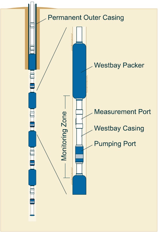
The left side diagram in Figure 8-4 shows a cross-section of a Westbay dedicated multi-level monitoring system in a vertical open hole. A permanent outer casing is located in the upper portion of the hole around the Westbay system. An annular seal is located around the outside of the permanent outer casing.
To the right of the Westbay system cross-section is an expanded view of the centre of the Westbay system in the hole. The upper portion of the expanded view shows the Westbay system’s casing extending vertically down to a Westbay packer. The packer has been expanded to the side of the hole. A casing is attached from the bottom of the packer to a measurement port. A casing is attached from the measurement port to a pumping port. A casing is attached from the pumping port to a lower packer. The lower packer has been expanded to the side of the hole.
Figure 8-5: Cross-Section of A Westbay ® System Completion in A Cased Well
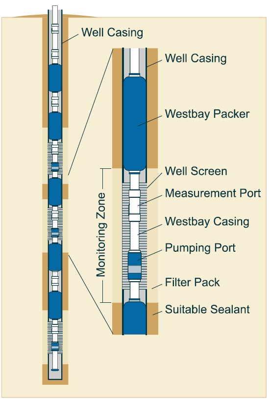
The left side diagram in Figure 8-5 shows a cross-section of a Westbay dedicated multi-level monitoring system in a vertical open hole. A vertical string of altering permanent outer casing and well screens are located in the hole around the Westbay system. The well screens are located in monitoring zones. An annular seal is located around the outside of the permanent outer casing and filter pack is located around the outside of the well screens in the hole.
To the right of the Westbay system cross-section is an expanded view of the centre of the Westbay system in the hole. The upper portion of the expanded view shows the Westbay system’s casing extending vertically down to a Westbay packer. The Westbay packer has been expanded to the side of a permanent casing in the hole. A Westbay casing is attached from the bottom of the packer to a measurement port. A casing is attached from the measurement port to a pumping port. A Westbay casing is attached from the pumping port to a lower packer. The lower packer has been expanded to a permanent outer casing. The zone between the two packers is called a Monitoring zone. In the monitoring zone, a well screen is attached between the two permanent outer casings. A filter pack material has been placed between the well screen and the side of the hole. A suitable sealant has been placed between the permanent outer casings and the side of the hole.
Reminder: These figures are not to scale, are for illustrative purposes only and do not necessarily represent full compliance with the requirements found in the Wells Regulation.
Figure 8-6: Cross-Section of A Westbay ® System in A Backfilled Hole
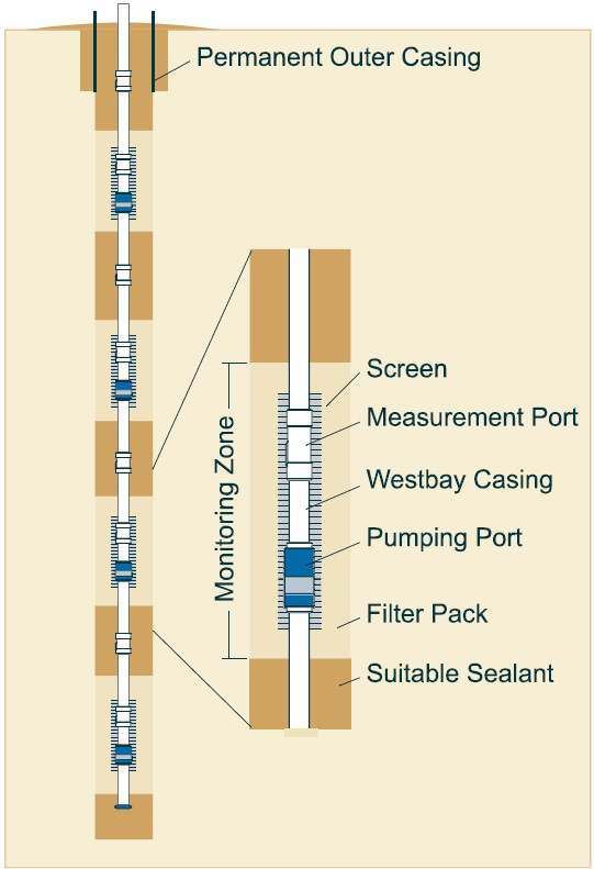
The left side diagram in Figure 8-6 shows a cross-section of a Westbay dedicated multi-level monitoring system in a vertical open hole. A permanent outer casing is located in the upper portion of the hole around the Westbay system. An annular seal is located around the outside of the permanent outer casing.
To the right of the Westbay system cross-section is an expanded view of the centre of the Westbay system in the hole. The upper portion of the expanded view shows the Westbay system’s casing extending vertically down to a measurement port. A casing is attached from the measurement port to a pumping port. A casing is attached from the pumping port and extends down into the hole. Above and below the pumping port and measurement port zone, a suitable sealant has been placed around the casing to the side of the hole. In the pumping port and measuring port zone, a filter pack has been placed from the ports to the side of the hole.
Reminder: This figure is not to scale, it is for illustrative purposes only and does not necessarily represent full compliance with the requirements found in the Wells Regulation. For example, an outer casing is required to allow a new system to be used for more than 180 days.
Figure 8-7: Sampler Probe For The Westbay ® System
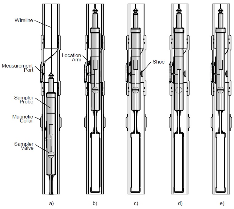
The diagram is a cross-section illustration that shows the 5 stages of a sampler probe in the Westbay System. The first two illustrations show the sampler probe locating a sampling port, the third illustration shows the system connecting to the port, the 4th shows that is collecting a sample and the fifth one shows the closing of the sample passage and storing of the sample.
The above cross-section illustrations show the various stages of a sampler probe in the Westbay ® System, locating a port (a) and (b), connecting to the port and monitoring (c), collecting a sample (d), and closing the sample passage (e).
Reminder: This figure is not to scale, it is for illustrative purposes only and does not necessarily represent full compliance with the requirements found in the Wells Regulation.
Figure 8-8: Stainless Steel Ports
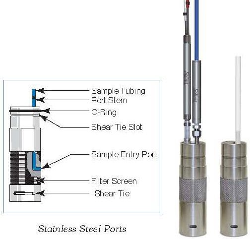
Figure 8-9: Permanent Waterloo Packer
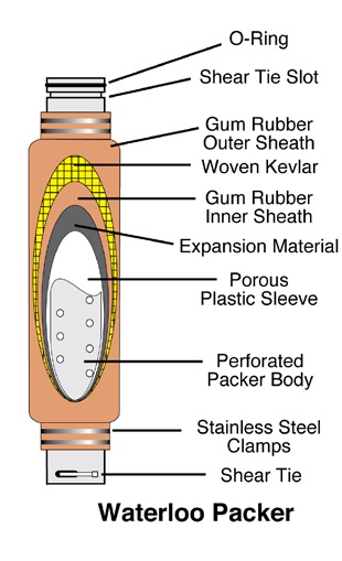
Figure 8-10: Manifold
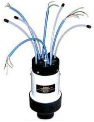
Figure 8-11: O-Ring With Shear Wire
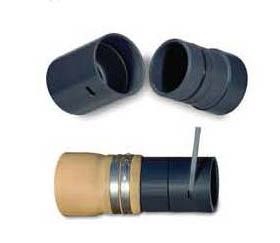
Figures 8-8 to 8-11, show various components for a Solinst Waterloo™ system. The ports (Figure 8-8) connect monitoring equipment with a groundwater zone. Packers (Figure 8-9) can be expanded to seal the system to the side of the well. A manifold (Figure 8-10) seals the top of the system. Connections using O-rings and shear wires (Figure 8-11) provide a watertight connection between casing, packers and ports. The figure shows the components assembled and placed into the ground.
Reminder: Figure 8-8 to Figure 8-11 are for illustrative purposes only and do not necessarily represent full compliance with requirements found in the Wells Regulation.
Figure 8-12: Examples of Three Completions of the Solinst Waterloo™ System
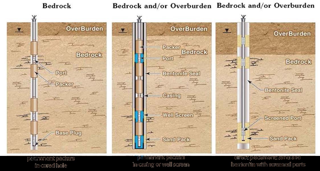
The first example on the left shows a cored hole in bedrock with no casing. Permanent packers are placed in the cored hole above and below the monitoring port. The 2nd example in the middle shows a cored hole that can either be in bedrock or the overburden. In this example, well casing is placed inside the cored hole and permanent packers are in the casing or well screen. The third example on the right side of the figure shows a cored hole that can either be in bedrock and/or overburden. In this case sand and bentonite is placed directly around screen monitoring ports.
Reminder: This figure is not to scale, it is for illustrative purposes only and does not necessarily represent full compliance with the requirements found in the Wells Regulation. For example, a permanent outer casing is required to allow a new multi-level monitoring system to be used for more than 180 days.
Figure 8-13: Details of A Sampling Port Construction in A Solinst CMT™ (Continuous Multi-Channel Tubing™) System
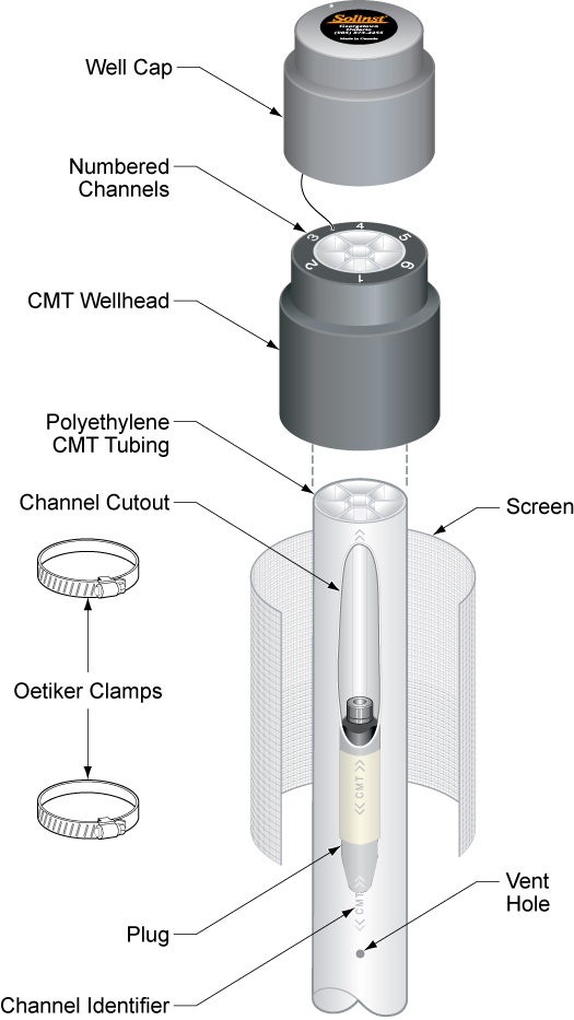
This figure shows the components that make up a CMT system. From top to bottom, the system includes a well cap, a CMT wellhead that contains numberd channels within it. Attached below and within the wellhead is polyethylene CMT tubing with a screen wrapped around it. Oetiker Clamps hold the screen on the CMT tubing
.
Reminder: This figure is not to scale, it is for illustrative purposes only and does not necessarily represent full compliance with the requirements found in the Wells Regulation.
Figure 8-14: Seven-Channel MDPE Tubing in A Solinst CMT™ (Continuous Multi-Channel Tubing™) System
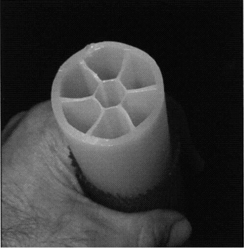
Figure 8-15: A Person Laying Out The MDPE Tubing Prior To Installation In The Hole
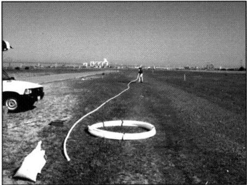
Reminder: To prevent contamination to the groundwater and to meet the Wells Regulation, persons should lay out MDPE tubing on clean plastic sheets rather than directly onto the ground as shown in Figure 8-15.
Reminder: These figures are for illustrative purposes only and do not necessarily represent full compliance with the requirements found in the Wells Regulation.
Figure 8-16: Screened Port Completion
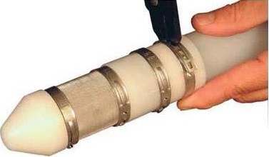
Figure 8-16 shows a screened port completion for the centre channel of a Solinst CMT™ (Continuous Multi-channel TubingTM) system. The port is called a guide point port assembly and is attached to the bottom of the MDPE tubing.
Figure 8-17: Guide Port Assembly Anchor
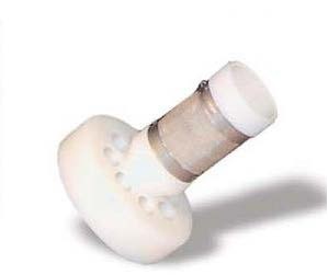
Figure 8-18: Centralizer On MDPE Tubing
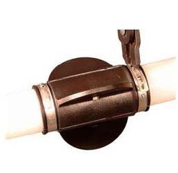
Figure 8-18 shows a three half circle centralizer clamped onto the MDPE tubing. The centralizer helps centre the MDPE tubing in the hole.
Reminder: These figures are for illustrative purposes only and do not necessarily represent full compliance with the requirements found in the Wells Regulation.
Figure 8-19: Example Of Solinst CMT System Completion
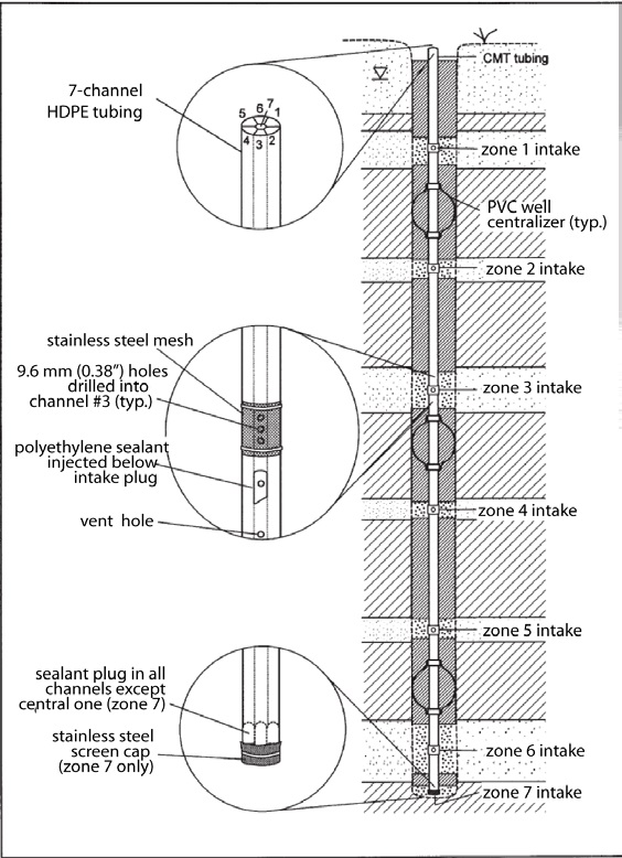
Reminder: These figures are not to scale, are for illustrative purposes only and do not necessarily represent full compliance with the requirements found in the Wells Regulation. For example, a permanent outer casing is required to allow a new system to be used for more than 180 days.
Figure 8-20: Cross-Section Of A Water Flute™ System
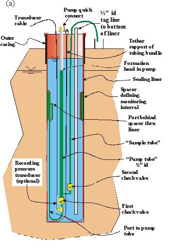
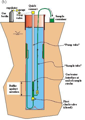
Reminder: These figures are not to scale, are for illustrative purposes only and do not necessarily represent full compliance with the requirements found in the Wells Regulation.
Figure 8-21: Installation of A Water FLUTe™ Into A Test Hole
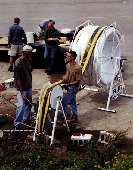
Figure 8-21 shows the factory-made installation of a Water FLUTe™ into a test hole, using the eversion process. The liner was shipped to the site fully fabricated on the shipping reel in the background. The bottom end of the liner is entering the hole and the pump systems for the ports will follow it to the bottom of the hole. The pump tubing is sheathed in a diagonally woven white cover containing the pumps, the 15 transducers and cables, the supporting tether and the tag line.
Reminder: This figure is for illustrative purposes only and does not necessarily represent full compliance with the requirements found in the Wells Regulation.
Casing And Well Screen Requirements
The material used in a dedicated multi-level monitoring system may be plastic, stainless steel, polytetrafluoroethylene, fiberglass or polyurethane-coated nylon fabric (sometimes called a sock or liner).
The materials used to make casing should be designed to support the sides of a well to prevent the present and future collapse of overburden and bedrock formations into the well.
Where a pipe, tube or other material (e.g., liner) in a dedicated multi-level monitoring system is used to support the sides of a well, the material is considered “casing” under the Wells Regulation. In some cases, such as the Solinst Waterloo™ system, a manifold is used to house all of the monitoring tubes and cables at the top of the system. Where a portion of the manifold is being used to support the sides of the test hole, the manifold is considered “casing”.
The Wells Regulation - The casing requirements and exemptions of the Wells Regulation that are outlined in the “The Requirements – Plainly Stated” section of Chapter 6: Constructing the Hole, Casing & Covering the Test Hole or Dewatering Well apply to the lengths of casing in a dedicated multi-level casing system. Also, any permanent outer casing that is placed around the dedicated multi-level casing system must meet casing requirements and exemptions of the Wells Regulation.
Where the pipe, tube or other material is part of a port to sample or monitor groundwater, the pipe, tube or other material is considered a “well screen” under the Wells Regulation. This includes port areas that are wrapped in a screen mesh or part of a spacer area in a liner (see Figure 8-16, Figure 8-17, and Figure 8-20).
The Wells Regulation - The well screen requirements and exemptions of the Wells Regulation that are outlined in the “Plainly Stated” section of Chapter 6: Constructing the Hole, Casing & Covering the Test Hole or Dewatering Well apply to the port areas, including spacer areas, in a dedicated multi-level casing system.
The exemptions in the Wells Regulation allow for the use of unique casing and port designs in a dedicated multi-level casing system to obtain groundwater samples and to determine groundwater characteristics that are representative of the study area.
The Wells Regulation - If a new dedicated multi-level casing system is finished above the ground surface, the minimum casing extent and casing height requirements in the Wells Regulation that are outlined in Chapter 9: Completing the Test Hole or Dewatering Wells Structure apply as long as the upper part of the system is using a length of material that is defined as “casing”.
For example, if a new Solinst Waterloo CMT™ system is installed in an overburden hole, the person constructing the well must ensure the HDPE casing extends:
- from the water intake zone,
- to at least 40 cm (16″) above the highest point on the ground surface within 3 m (10′) radially from the outside of the casing after the ground surface (surface drainage) has been mounded so that water will not collect or pond near the well as measured on completion of the well’s structural stage.
The Wells Regulation - If the new dedicated multi-level casing system is located in an area where there is a likelihood of pedestrian or vehicular traffic, the Wells Regulation allows for the top of the casing to be finished below the ground surface as long as the person constructing the well completes the well with a flush-mounted well cover and meets the Wells Regulation requirements. See Chapter 9: Completing the Test Hole or Dewatering Well Structure for more information on flush-mounted well covers. See Chapter 12: Equipment Installation for further information on flush-mounted well pit (vault) construction requirements.
The Wells Regulation - The top of the dedicated multi-level casing system must be covered or capped in accordance with the Wells Regulation requirements. See “Plainly Stated” section in Chapter 12: Equipment Installation for further information.
Records of Site Condition Regulation - Starting on July 1, 2011, amendments to O. Reg. 153/04 came into force and apply to phase two environmental site assessments (ESAs) conducted in support of records of site conditions (RSCs). For any such RSC submitted on or after this date, where a groundwater sampling method is to be used to characterize contamination or determine if the concentration of a contaminant is above, at or below and applicable site condition standard or standard specified in a risk assessment for the contaminant, the following requirements apply to the construction of a well:
- where a monitoring well is being used, well screens shall not exceed 3.1 m (10′) in length, based on the saturated length of the screen, and
- where petroleum hydrocarbons or light non-aqueous phase liquids may be present on, in or under a phase two property, sampling depth intervals, including screened intervals of monitoring wells, shall be positioned to intersect the water table.
Implications for the Qualified Person
The qualified person shall ensure that the phase two ESA is conducted in accordance with requirements stated above.
Records of Site Condition Regulation - Please refer to O. Reg. 153/04 for RSC requirements.
Reminder: For clarification of the term “monitoring well” and “qualified person” as they relate to the O. Reg. 153/04, see Chapter 2: Definitions & Clarifications, Table 2-2.
Annular Space Requirements - Operating Not Later Than 180 Days
This section applies to a new test hole that is scheduled to be abandoned not later than 180 days after the completion of the structural stage of the test hole, and where an outer permanent casing is not placed around the new dedicated multi-level casing system.
The Wells Regulation - Instead of following the annular space requirements listed in Chapter 7: Annular Space and Sealing, the person constructing a new dedicated multi-level casing system new multi-level monitoring without a permanent outer casing must ensure that:
- any annular space created beside a casing or between casings is sealed to prevent the movement of water, natural gas, contaminants or other material between a subsurface formations or between a subsurface formation and the ground surface, and
- the test hole is scheduled to be abandoned not later than 180 days after the completion of the structural stage of the test hole.
Reminder: See the “Best Management Practice –Written Contract for Wells Scheduled to be Abandoned” in the “Bundled Multi-level Monitoring Test Hole” section in this chapter.
Records of Site Condition Regulation - Starting on July 1, 2011, O. Reg. 153/04 prescribes that the provisions of the Ontario Water Resources Act and of Regulation 903 of the Revised Regulations of Ontario, 1990 (Wells) made under that Act, that would apply to a test hole but for section 1.1, and subsections 13 (2), 14.1 (2), 14.2 (3), 14.3 (2), 14.4 (4) and 14.5 (3) of that regulation, apply to a monitoring well installed for the purpose of,
- a phase one environmental site assessment; and
- a phase two environmental site assessment.
Implications for the Qualified Person
The qualified person shall ensure that phase one and phase two environmental site assessments (ESAs) are conducted in accordance with the requirement stated above.
Implications for Annular Space for New Test Holes
With respect to annular space size and filling, the above requirement in the O. Reg. 153/04 means that, if the new dedicated multi-level monitoring test hole is constructed and is scheduled to be abandoned not later than 180 days after the completion of its structural stage, and is to be used as a monitoring well in an ESA for a record of site condition, then:
- the annular space size and filling exemptions for a test hole stated in this section do not apply and
- the annular space size and filling requirements for a test hole stated in the “Annular Space – Operating Longer than 180 Days” section do apply regardless of the amount of time that the monitoring well will be in operation.
Reminder: The above requirement in O. Reg. 153/04 also affects obligations such as shallow works, casing material and annular space filling for monitoring wells. See Chapter 3: Exemptions: Wells, Activities & Experienced Professionals, Chapter 6: Constructing the Hole, Casing & Covering the Test Hole or Dewatering Well and Chapter 7: Annular Space & Sealing for further information.
Reminder: Please refer to O. Reg. 153/04 for RSC requirements.
Annular Space - Operating Later Than 180 Days
The Wells Regulation allows for a new dedicated multi-level casing system that will be in operation for more than 180 days after the completion of the well’s structural stage, if the following casing and annular space requirements are met:
The Wells Regulation - The person constructing the test hole must install a permanent outer casing around the dedicated multi-level casing system.
In situations where a casing and screen string is employed in the construction of the new dedicated multi-level casing test hole, the person constructing the test hole must install a permanent outer casing around the casing and screen string.
The Wells Regulation Depending on the type of well construction method used, the person constructing the new dedicated multi-level casing test hole must follow the Wells Regulation requirements listed in Chapter 7: Annular Space & Sealing, Table 7-1 A and Table 7-1B to create and seal any annular space on the outside of the permanent outer casing.
Reminder: As a necessary modification for systems installed using drilling, augering or sonic equipment, the depth of the annular space must extend from the ground surface to at least the bottom of the permanent outer casing or 6 m (19.7′), whichever is less.
The Wells Regulation The person constructing the new dedicated multi-level test hole must seal the annular space between casings with a suitable sealant to prevent the entry of surface water and other foreign materials into the well. Depending on the environment, a suitable sealant could include a bentonite product, a cement product or a mechanical device such as a packer.
The Wells Regulation If any groundwater is entering the annular space between casings, the entire annular space between the casings must be sealed, with necessary modifications, in accordance to the minimum requirements of Chapter 7: Annular Space & Sealing, Table 7-1 A and Table 7-1B. The annular space between casings of a well constructed by the use of a driven point is not required to be sealed in accordance with Chapter 7: Annular Space & Sealing, but is required to be sealed with a suitable sealant.
Reminder: The annular space creation and filling method requirements in the Wells Regulation do not apply to any annular space located below the bottom of the permanent outer casing. The regulatory exemptions regarding sealing the annular space below the permanent outer casing allow for well technicians, engineers and geoscientists to use their professional expertise to design and install multi-level wells on a case by case basis, thereby enabling the testing and sampling of various groundwater intervals while preventing contamination.
Reminder: For further information on creating and filling an annular space for multi-level systems, see the Best Management Practice – Designing and Placing Sealant in Dedicated Multi-Level Systems on page 64 of this chapter.
The installation of an inner and permanent outer casing is referred to as a double walled casing in the Wells Regulation.
Although a person constructing a well is not specifically required to seal around casings between well screens or ports in a dedicated multi-level monitoring test hole below the permanent outer casing; the person must do what is necessary as the Ontario Water Resources Act prohibits every person from discharging or causing or permitting the discharge of any material of any kind into any waters that may impair the quality of any waters. This includes prohibiting contaminated groundwater from impairing the quality of other groundwater zones when constructing a well.
The regulatory exemptions regarding sealing the annular space below the permanent outer casing allow for well technicians, engineers and geoscientists to use their professional expertise to design and install a bundled system on a case by case basis, thereby enabling the testing and sampling of various groundwater intervals while preventing (further) contamination.
Persons using such professional judgement and the well owner should be aware of the following requirement:
The Wells Regulation - If the test hole or dewatering well acts as a pathway for the movement of:
- natural gas,
- contaminants, or
- other materials
between subsurface formations (including aquifers) or between the ground surface and a subsurface formation and where the movement may impair the quality of the any waters, the person abandoning the well, often the well owner, must do one of the following:
- take measures to prevent the movement of the above materials and ensure the measures are functional at all times, or
- immediately abandon the well.
The Wells Regulation requires that, at all times, steps must be taken by the well owner to prevent the well from acting as a pathway for contaminants that may impair groundwater resources.
Reminder: Further information on abandonment requirements is provided in Chapter 16: Abandonment: When to Plug & Seal Test Holes & Dewatering Wells and Chapter 17: Abandonment: How to Plug & Seal Test Holes & Dewatering Wells of this manual.
Examples
The following provides four examples of the well construction requirements for new dedicated multi-level monitoring test holes that will be in operation more than 180 days.
Example A: Installing the Westbay® System using Dual Rotary Equipment
Example B: Installing a Continuous Multi-Channel Tubing™ (CMT™) using Sonic Equipment
Example C: Installing a water FLUTe™ liner using Dual Rotary Equipment
Example D: Installing a casing and screen string and Waterloo™ system using Sonic Equipment
Example A: Installing the Westbay® System using Dual Rotary Equipment
A person constructing a dedicated multi-level monitoring test hole uses dual rotary equipment to advance a hole in the ground. The person constructing the test hole completes the well in the following manner:
-
A hole, that must be at least 7.6 cm (3″) larger than the outside diameter of a permanent outer casing, is advanced to 4 m (13′) below the ground surface. The hole is drilled through 3 m (10′) of overburden and 1 m (3.3′) of competent bedrock. A temporary outer casing that is the same size as the hole is advanced during the drilling process.
A permanent outer casing is installed into the test hole to 4 m (13’) below the ground surface.
- As required by the Wells Regulation, the annular space between the permanent outer casing and temporary outer casing is filled with suitable sealant using a tremie pipe. The temporary outer casing is used as the tremie pipe to place the suitable sealant into the annular space. As an alternative, a small diameter tremie pipe can be installed in the annular space to place the sealant (see Chapter 7: Annular Space & Sealing for further information). As required by the Wells Regulation, the tremie pipe is immersed in the rising accumulation of the suitable sealant. The suitable sealant must prevent the movement of water, natural gas, contaminants or other materials between subsurface formations or between a subsurface formation and the ground surface. The temporary outer casing is then removed.
- A smaller diameter hole is drilled below the permanent outer casing to the predetermined depth. The hole is advanced through competent bedrock. A temporary inner casing is advanced during the drilling process to the full depth of the hole. The temporary inner casing acts to hold the hole open and to reduce the risk of contaminants and groundwater moving along the well column. The drilling tools are removed from the hole.
- After assessing geophysical and hydrogeological information taken during or shortly after drilling, the intervals for monitoring and sampling groundwater are determined to design the Westbay® System. Based on the information, casing, inflatable packers and port components of the Westbay® System are assembled on site and placed into the hole.
- The small diameter temporary inner casing is raised to expose each port and packer.
- Using the best management practices outlined in this chapter, each packer is inflated to seal the system to the sides of the Westbay® System’s casing. The process is repeated until all ports are installed and all packers are expanded.
- As required by the Wells Regulation, the annular space between the dedicated multi-level casing and the permanent outer casing is sealed with suitable sealant, such as a bentonite product, a cement product or an inflatable packer, to prevent the entry of surface water and other foreign materials into the well. In addition, if groundwater is leaking into the annular space between the casing of the sampling system and the permanent outer casing, a suitable sealant must be installed in the same manner as Step 3 of this example.
- As required by the Wells Regulation, the annular space between the dedicated multi-level casing and the permanent outer casing is sealed with a suitable sealant, such as a bentonite product, a cement product or an inflatable packer, to prevent the entry of surface water and other foreign materials into the well. In addition, if groundwater is leaking into the annular space between the casing of the sampling system and the permanent outer casing, a suitable sealant must be installed in the same manner as Step 7 of this example.
Example B: Installing a Continuous Multi-Channel TubingTM (CMT™) using Sonic Equipment
A person constructing a dedicated multi-level monitoring test hole uses sonic drilling equipment to advance a hole in the ground. The person constructing the test hole completes the well in the following manner:
- A hole, that must be at least 7.6 cm (3”) larger than the outside diameter of the permanent outer casing, is advanced from ground surface to at least the predetermined bottom of the permanent outer casing. A temporary outer casing that is the same size as the hole is advanced during the drilling process.
- A smaller diameter hole is drilled below the temporary outer casing to the predetermined depth. A temporary inner casing is advanced during the drilling process to the full depth of the hole. The temporary inner casing acts to keep the hole open and reduces the risk of contaminants and groundwater moving along the well column. The drilling tools are removed from the hole.
- Based on hydrogeological information obtained during the drilling process and using the installation recommendations of the manufacturer, seven ports are created on a length of MDPE tubing of a Continuous Multi-Channel Tubing™ (CMT™) system. One of the ports is located at the bottom of the MDPE tubing. As a best management practice, centralizers are placed around the MDPE tubing at various intervals to ensure the CMT™ will be centered in the hole. The CMT™ is installed into the hole.
- Using the best management practices outlined in Chapter 6: Constructing the Hole, Casing & Covering the Test Hole or Dewatering Well for filter pack installation, inert sand is carefully poured down the annular space around the MDPE tubing to create a filter pack around the deepest well screen. Using the best management practices found in Chapter 7: Annular Space & Sealing, a suitable sealant is installed in the annular space from the top of the filter pack up to almost the next port. The best management practices of placing sand and suitable sealant are repeated until the process reaches the bottom of the temporary outer casing.
- The temporary inner casing, used to hold the hole open, is lifted up and out of the well exposing all ports with filter packs to the formations.
- A permanent outer casing is installed into the test hole between the MDPE tubing and temporary outer casing. The permanent outer casing should be installed to a depth above the top of the upper port.
- As required by the Wells Regulation, the annular space between the permanent outer casing and temporary outer casing is filled with suitable sealant using a tremie pipe. The temporary outer casing is used as the tremie pipe to place the suitable sealant into the annular space. As an alternative, a small diameter tremie pipe can be installed in the annular space to place the sealant (see Chapter 7: Annular Space & Sealing for further information). As required by the Wells Regulation, the tremie pipe is immersed in the rising accumulation of the suitable sealant. The suitable sealant must prevent the movement of water, natural gas, contaminants or other materials between subsurface formations or between a subsurface formation and the ground surface. The temporary outer casing is then removed.
- As required by the Wells Regulation, the annular space between the permanent outer casing and the inner casing of the CMT™ is sealed with a suitable sealant such as a bentonite product, a cement product or a mechanical device such as a packer, to prevent the entry of surface water and other foreign materials into the well. In addition, if groundwater is leaking into the annular space between the CMT™ and the permanent outer casing, a suitable sealant must be installed in the same manner as Step 7 of this example.
Example C: Installing a water FLUTe™ liner using Dual Rotary Equipment
A person constructing a dedicated multi-level monitoring test hole uses dual rotary equipment to advance a hole in the ground. The person constructing the test hole completes the well in the following manner:
- A hole, that must be at least 7.6 cm (3″) larger than the outside diameter of the permanent outer casing, is advanced from ground surface to at least the predetermined bottom of the permanent outer casing. A temporary outer casing that is the same size as the hole is advanced during the drilling process.
- A permanent outer casing is installed into the test hole. As a best management practice, the permanent outer casing is installed to a depth just above the top of the upper port. This location represents a highly fractured bedrock zone below competent bedrock.
- As required by the Wells Regulation, the annular space between the permanent outer casing and temporary outer casing is filled with suitable sealant using a tremie pipe. The temporary outer casing is used as the tremie pipe to place the suitable sealant. As an alternative, a small diameter tremie pipe can be installed in the annular space to place the suitable sealant (see Chapter 7: Annular Space & Sealing for further information). As required by the Wells Regulation, the tremie pipe is immersed in the rising accumulation of the suitable sealant. The suitable sealant must prevent the movement of water, natural gas, contaminants or other materials between subsurface formations or between a subsurface formation and the ground surface. The temporary outer casing is then removed.
- A smaller diameter hole is drilled below the permanent outer casing to the pre-determined depth. The hole is advanced through competent bedrock. A temporary inner casing is advanced during the drilling process to the full depth of the hole. The temporary inner casing acts to hold the hole open and to reduce the risk of contaminants and groundwater moving along the well column. The drilling tools are removed from the hole.
- The temporary inner casing is removed from the hole. A factory-made water FLUTe™ liner with no ports is installed into the hole using an eversion technique with water. The water inside the liner holds the hole open in the highly fractured bedrock zone and reduces the risk of contaminants and groundwater moving along the well column.
- Based on hydrogeological information obtained during the drilling process and all other available information from geophysical measurements and transmissivity measurements during the blank liner installation in this hole, a factory-made water FLUTe™ liner with specially made ports, tubing and cables is made and arrives at the well site. The water FLUTe™ liner with no ports is removed and the water FLUTe™ liner with ports is placed into the hole under the supervision of persons properly trained to install the liner using an eversion process.
- The liner seals to the permanent outer casing, fractured bedrock zone and deeper competent bedrock. The liner is considered casing because it is supporting the sides of the well including the portion of the highly fractured bedrock zone. However, as there is no annular space between the liner and the permanent outer casing, suitable sealant is not required to be placed between the liner and outer casing.
Example D: Installing a casing and screen string and Waterloo™ system using Sonic Equipment
A person constructing a dedicated multi-level monitoring test hole uses sonic drilling equipment to advance a hole in the ground. The person constructing the test hole completes the well in the following manner:
- A hole, that must be at least 7.6 cm (3″) larger than the outside diameter of the permanent outer casing, is advanced through overburden and a highly fractured bedrock formation to at least the predetermined bottom of the permanent outer casing. A temporary outer casing that is the same size as the hole is advanced during the drilling process.
- A permanent outer casing is installed into the test hole to a depth just above the top of the upper port.
- As required by the Wells Regulation, the annular space between the permanent outer casing and temporary outer casing is filled with suitable sealant using a tremie pipe. The temporary outer casing is used as the tremie pipe to place the suitable sealant. As an alternative, a small diameter tremie pipe can be installed in the annular space to place the suitable sealant (see Chapter 7: Annular Space & Sealing for further information). As required by the Wells Regulation, the tremie pipe is immersed in the rising accumulation of the suitable sealant. The suitable sealant must prevent the movement of water, natural gas, contaminants or other material between subsurface formations or between a subsurface formation and the ground surface. The temporary outer casing is then removed.
- A smaller diameter hole is drilled below the permanent outer casing to the predetermined depth. A temporary inner casing is advanced during the drilling process to the full depth of the hole. The temporary inner casing acts to keep the hole open and to reduce the risk of contaminants and groundwater moving along the well column. The drilling tools are removed from the hole.
- After assessing geophysical and hydrogeological information taken during or shortly after drilling, the intervals for a casing and screen string are determined. The stainless steel casing sections and well screen lengths are joined together to form a casing and screen string. The string is placed into the hole. The well screens are designed to match sampling depths and intervals that are to be sampled or monitored.
- Using the best management practices in the “Filter Packs around Well Screens for Test Holes or Dewatering Wells” and “Artificial Filter Packs” sections of Chapter 6: Constructing the Hole, Casing & Covering the Test Hole or Dewatering Well, inert sand is carefully poured down the annular space of the hole to create a filter pack around the deepest well screen. Using the best management practices found in Chapter 7: Annular Space & Sealing, a suitable sealant is installed in the annular space from the top of the filter pack up to almost the next sampling interval. The best management practices of placing sand and suitable sealant are repeated until the process reaches the bottom of the temporary outer casing.
- The temporary inner casing, used to hold the hole open, is lifted up and out of the well exposing all well screens with filter packs to the formations. During this process the well screen areas should be developed to remove any drilling mud and to repair damage done to the formation.
- Ports, tubing, cables, casing, inflatable packers and a manifold are assembled to create a Waterloo™ system based on the geophysical and hydrogeological information taken during, or shortly after, drilling and the present location of well screens in the casing and screen string. The system is placed in the hole with individual ports matching the depths of individual well screens.
- Using the best management practices outlined in this chapter, the packers are inflated to seal the system to the sides of the steel casing.
- As required by the Wells Regulation, the annular space between the shallowest casing of the Waterloo™ system and the shallowest section of the casing and well string is sealed with a suitable sealant such as a bentonite product, cement product or a mechanical device such as a packer to prevent the entry of surface water and other foreign materials into the well. In addition, if groundwater is leaking into the annular space between the shallowest casing of the Waterloo™ system and the shallowest section of the casing and well string, a suitable sealant must be installed in the same manner as Step 3 of this example.
Decicated Multi-Level System - Best Management Practices
Best Management Practice – Sealing the Upper Portion of the Test Hole
The person constructing the dedicated multi-level monitoring test hole should consider designing and constructing the permanent outer casing to the recommendations found in:
- “Best Management Practice – Length and Sealing of Permanent Outer Casing for a Bundled Multi-Level Monitoring Test Hole” on page 19 of this chapter
- “Best Management Practice – Sealing the Annular Space around the Inner Casings for a Bundled Multi-Level Monitoring Test Hole” on page 19 of this chapter
- “Best Management Practice – Sealing a Bundled Multi-Level Monitoring Test Hole Constructed by the Use of a Driven Point” on page 20 of this chapter
Reminder: There are many factors that affect the casing selection including depth of the well and water quality.
Reminder: Some materials such as ABS, polytetrafluoroethylene (PTFE) (e.g. Teflon), fiberglass and glass are not typically used for casing for test holes. It is important to refer to manufacturer’s specifications and other information to determine if the material is appropriate for use in test holes at a specific site.
Reminder: A downhole video camera should be used to visually observe the casing, casing joints, the seal between the screen and casing as long as a contaminant will not interfere with the device.
Best Management Practice – Installing Temporary Casing to Bottom of Hole
When constructing a hole through a potential contaminant plume in unconsolidated and consolidated formations, a temporary casing that is the size of the hole should be advanced during the construction process. The temporary casing reduces the risk of the vertical migration of contaminants in the hole during the installation of casing and sealing of the test hole. Dual rotary (barber) drilling rigs, sonic drilling rigs and auger rigs can allow for the installation of the recommended temporary casing while advancing the hole. The temporary casing should be large enough to allow for the placement of casing, filter packs and suitable sealant.
Best Management Practice – Locating Dedicated Multi-level Systems on Highly Contaminated Sites
Where there is a high potential for cross–contamination, dedicated multi-level systems should be tested and evaluated to determine if they can be installed. If testing shows that the system has a high probability of cross-contamination, installing single wells with properly sealed annular spaces may be an alternative to reduce the risk of the vertical movement of a contaminant from one groundwater zone to another.
Best Management Practice – Installing Dedicated Multi-level Systems Immediately after Creating the Hole
If feasible, when constructing a hole through a contaminant plume, the person constructing the dedicated multi-level monitoring test hole should immediately install the dedicated system within the hole and properly seal the areas in between ports to reduce the risk of the vertical migration of contaminants between groundwater zones.
In the case of the water FLUTe™, a blank liner should be immediately installed in the hole to the manufacturer’s specifications. The liner creates a seal along the side of the hole to reduce the risk of the vertical migration of contaminants between groundwater zones. When the factory-ordered water FLUTe™ with ports arrives on the site, the blank liner can be removed and the liner with ports can be installed into the hole.
Proper well development, purging, field and laboratory water sampling and interpretation of the parameters should be undertaken to verify that the well construction has not allowed for the migration of contaminants. If it is determined contaminants have migrated between zones, steps need to be taken to alter (repair) the well. As an alternative, the well should be properly abandoned and a new test hole constructed.
Best Management Practice – Size of Hole and Use of Centralizers and Centering Discs in Dedicated Multi-level Systems
Installation of a system without packers or a liner creates difficulties in centering a dedicated multi-level system in a hole. If casing or ports are touching the side of the hole, sections of the hole may not be properly sealed creating voids in the suitable sealant or filter pack material. The voids can create vertical migration pathways for contaminants or groundwater. To reduce the risk of voids and allow for the proper placement of filter packs and suitable sealant for systems that do not use packers or a liner, the person constructing the test hole should:
- Create an initial hole that is large enough to provide sufficient space:
- between the dedicated pipe, ports or other components and the side of the test hole, and
- to allow for the installation of a tremie pipe.
- Install centralizers that separate the dedicated system components from the side of the hole while offering a space for a tremie pipe.
- Install centralizers near the top of the hole, below a well screen or at intervals of about 10 m (33′) between each location of the centralizers and disks.
- Install pre-packed sand packs and bentonite packers, as an alternative to centralizers.
Best Management Practice – Placing Filter Packs in Dedicated Multi-Level Systems
Where filter pack material is used around the ports of a dedicated multi-level monitoring test hole and around well screens in casing and screen strings, and in addition to the Wells Regulation, the best management practices and information found in the sections titled “Filter Packs around Well Screens for Drilled Test Holes or Dewatering Wells” and “Artificial Filter Packs” of Chapter 6: Constructing the Hole, Casing & Covering the Test Hole or Dewatering Well should be used to ensure the filter pack and secondary filter pack material:
- is inert,
- represents the best hydraulic conditions for sampling groundwater and measuring aquifer characteristics,
- is properly placed around ports, and
- is monitored to prevent the upper filter pack and suitable sealant material from sinking and clogging deeper ports.
Best Management Practice – Port Location in Dedicated Multi-level Systems
For an installation where a casing and screen string is used, the depths of the ports of a dedicated multi-level monitoring system should fall within the elevation of the well screens.
For a dedicated multi-level system to monitor a dedicated zone, the open intervals for the ports should not straddle two hydrostratigraphic formations that may have different hydraulic heads or parameter concentrations. Geophysical data, video assessments, hydraulic data and in some cases minimum regulatory requirements [e.g. screened interval requirements in O. Reg. 153/04 (Records of Site Condition regulation)] should guide the length of well screen or port.
For example, the zone length for a port should not be designed to take measurements or samples from two different water bearing fracture zones that have different geochemistry or static water levels in a bedrock test hole. If both water bearing fracture zones are sampled by the same port, a bias may occur in the sampling results and not be representative of the aquifer’s chemistry in the zone that is being observed.
Best Management Practice – Designing and Placing Sealant in Dedicated Multi-Level Systems
Where annular space is present, the person constructing the dedicated multi-level monitoring test hole should install a suitable sealant, which could include packers, between ports and in the upper portion of the test hole.
If a cement or bentonite product is used, the person constructing the test hole should follow the requirements and best management practices in Chapter 7: Annular Space & Sealing when determining the type of suitable sealant and when placing the suitable sealant in the hole.
If packer systems are used, the person constructing the test hole should consider the best management practice titled “Inflatable Packer Systems for Dedicated Multi-level Systems,” on the next page.
Proper use and placement of a suitable sealant in the test hole’s annular spaces ensure the material is compatible with the quality of the water, and reduces the risk of the well acting as a pathway for surface water and other foreign materials to enter groundwater.
Best Management Practice – Inflatable Packer Systems for Dedicated Multi-Level Systems
When used, inflatable packers should be properly designed and placed to reduce the risk of vertical migration of groundwater or contaminants. Leakage between zones can bias samples, provide incorrect measurements and cause impairment of groundwater.
If inflatable packers are used, well owners and their agents should conduct a maintenance program to ensure inflatable packers maintain their original sealing pressures. This could include undertaking continuous field and laboratory water sampling, reporting and interpretation of water quality parameters to verify that the seals have not allowed for the migration of contaminants or groundwater from other intervals. This could also include an inspection of the well and its components and comparing the results with previous reports. If possible, packer pressure should be monitored and adjusted if necessary after a round of groundwater sampling.
Best Management Practice – Adjusting Dedicated Multi-Level Systems
The dedicated system should not be moved or adjusted because the seals created by the packers or sealant may be compromised. Only skilled and trained persons should be sampling, monitoring or maintaining these systems to reduce the risk of any movement.
Best Management Practice – Obtaining and Following Manufacturer’s Advice for Dedicated Multi-Level Systems
When designing and installing dedicated multi-level systems, the person constructing the well should obtain the advice of the manufacturer in the design, installation and use of the system. Failing to follow the manufacturer’s installation and sampling procedures can lead to bias in sample results.
Where necessary, the person constructing the well should use staff from the manufacturer or persons properly trained or certified in the manufacturer’s system to assist in the design and installation of the system.
Reminder: All individuals working on the installation of the system must have the proper well contractor and well technician licences unless exempt under the Ontario Water Resources Act or the Wells Regulation. For further information on licensing and exemptions see: Chapter 3: Exemptions: Wells, Activities & Experienced Professionals and Chapter 4: Well Contractors & Well Technicians – Licences, Responsibilities & Exemptions.
Best Management Practice – Inflating the Liner
When designing and installing a Water FLUTe™ system in highly fractured bedrock, the person constructing the well should ensure the liner is made of a material that will not tear on the sharp bedrock ledges and will not burst in cavity areas of the hole where the liner will not be touching the wall of the hole.
All liner material should be factory tested prior to shipping to determine if the liner has any tears.
Water or drilling mud should be added to the liner to inflate and seal the liner to the sides of the well. The water level within the liner should be maintained at least 3 m (10′) above the highest head pressure in the well. The height of the water in the liner should allow for the full inflation of the liner to the sides of the well.
If the highest head pressure will not allow for a 3 m (10′) differential between the water level in the liner and the head pressure, a drilling mud should be considered as an alternative to water to ensure proper liner inflation. A tremie pipe should be built into the liner system to allow for the drilling mud to fill the liner completely.
The person constructing the well should measure the head pressure from all monitoring ports after the system is installed. This will allow for the determination of all head pressures from the discrete zones and allow for the person to adjust the liner water level to maintain a 3 m (10′) differential from the highest head pressure.
The person constructing the well should monitor the water level or the level of the drilling mud in the liner after the liner has been installed in the well. If the level drops to or below the pressure head, there is a potential that the liner has been torn or that port areas are leaking. The liner may then need to be removed and replaced.
The person constructing the well should use staff from the manufacturer or persons properly trained or certified in the manufacturer’s system to assist in the design and installation of the system.
Diagrams Of Multi-Level Monitoring Systems
Figures 8-22 and 8-23 show cross-sectional illustrations and relevant graphics for various types of test holes that have been discussed in this chapter. The illustrations include the minimum size of the hole, the length of well casing, the type of well screen and the annular space filling materials around the well screen.
Reminder: All figures and diagrams are for illustrative purposes only and do not necessarily represent full compliance with the requirements found in the Wells Regulation (e.g. well covering during construction).
For details on the requirements involved in constructing the hole, sealing the annular space and completing the well, refer to the following chapters in this manual:
- Chapter 6: Constructing the Hole, Casing & Covering the Test Hole or Dewatering Well
- Chapter 7: Annular Space & Sealing
- Chapter 9: Completing the Test Hole or Dewatering Well Structure
Reminder: Each of the wells shown in Figure 8-22 and Figure 8-23 may encounter conditions that require specialized design or construction. For example:
- Flowing artesian conditions
- Presence of gas
- Sucking and blowing (breathing) conditions where the well and aquifer formation are significantly affected by changes in atmospheric pressure
Reminder: The illustrations and graphics may not depict every circumstance.
Figure 8-22: Examples Of Multi-Level Monitoring Systems (Must Be Scheduled To Be Abandoned Within 180 Days After Completing Structural Stage)
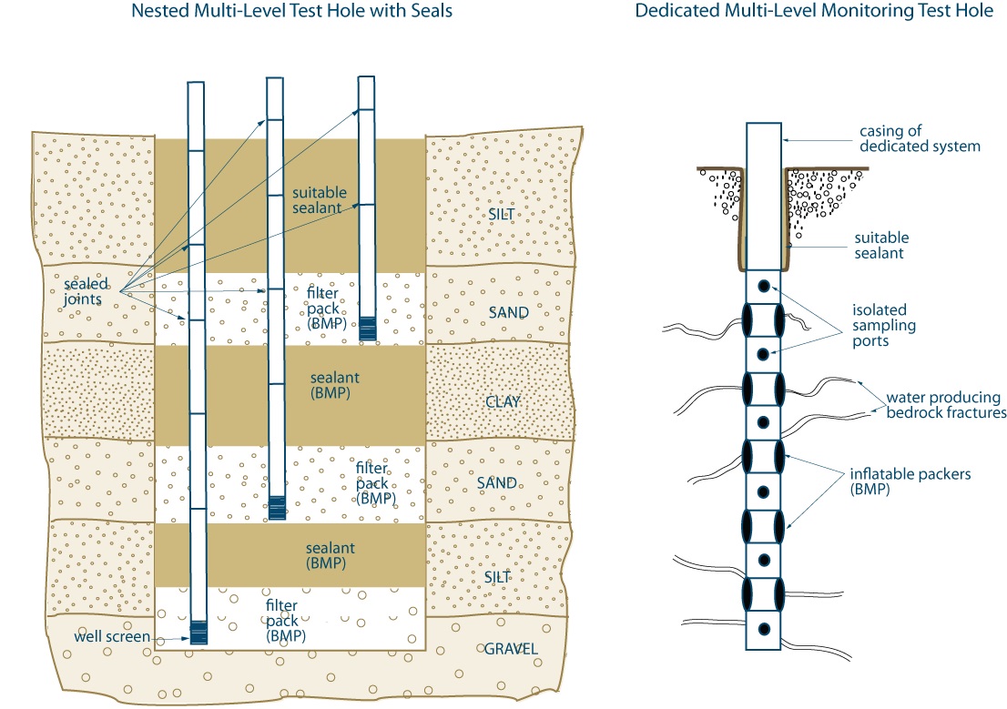
Figure 8-22 shows a cross-sectional diagram of two examples of multi-level monitoring systems that must be abandoned not later than 180 days after completing the well’s structural stage.
The diagram shows a nested multi-level test hole with seals on the left side of the diagram and a dedicated multi-level monitoring test hole on the right side of the diagram.
On the left side of the diagram, a nested multi-level test hole with seals is constructed through an upper silt, upper sand, clay, lower sand, lower silt and gravel deposits. The nest consists of three casings with well screens attached to the bottom of the casings. The joints on all of the casings have been sealed.
On the left side of the hole in the diagram, a casing and well screen extend from above the ground surface to the gravel deposit. As a best management practice, filter pack material is placed around the well screen and the lower portions of the casing. As a best management practice, a layer of sealant is placed above the filter pack to the top of the lower silt deposit.
In the centre of the hole in the diagram, a casing and well screen extend from above the ground surface to the lower sand deposit. As a best management practice, filter pack material is placed around the well screen and the lower portions of the centre casing in the lower sand deposit. The filter pack material also fills around the casing on the left side of the diagram. As a best management practice, a layer of sealant is placed around the casings from above the filter pack to the top of the clay deposit.
On the right side of the hole in the diagram, a casing and well screen extend from above the ground surface to the upper sand deposit. As a best management practice, filter pack material is placed around the well screen and the lower portions of the right casing in the upper sand deposit. The filter pack material also fills around the casings on the left side and centre area of the diagram. A suitable sealant is placed around the casings from the ground surface to the top of the upper sand deposit.
On the right side of the diagram, a dedicated multi-level monitoring test hole is constructed through overburden and into the bedrock. The upper portion of the dedicated system consists of a casing that extends vertically above the ground surface, through the overburden and into the bedrock. A suitable sealant is placed in the annular space adjacent to the casing from the ground surface to the bottom of the casing. An isolated sampling port is attached to the bottom of the casing in the bedrock. As a best management practice, an inflatable packer is attached to the bottom of the sampling port. Five additional sampling ports and four packers have been attached below the upper packer in the same sequence as with the upper sampling port and packer. The diagram also shows the dedicated multi-level system intersecting water producing bedrock fractures.
This diagram shows two examples of the many types of multi-level monitoring systems. For test holes and dewatering wells that are not scheduled to be abandoned within 180 days, the Wells Regulation requires that a continuous column of suitable sealant be placed above the filter pack material (see subparagraph ii, paragraph 1 of subsection 14.4 (2) of the Well Regulation). The two systems depicted above require separate zones of sealant materials to separate the different well screens and filter packs or ports. As such, these systems cannot meet the regulatory requirements for a test hole that will be in operation for more than 180 days and must be scheduled to be abandoned within that time. See Figure 8-24 for a multi-level monitoring system installed with a permanent outer casing.
Reminder: This figure is not to scale, it is for illustrative purposes for this chapter only and does not necessarily represent full compliance with the requirements found in the Wells Regulation.
Figure 8-23: Examples of Multi-Level Monitoring Systems (Not Scheduled To Be Abandoned Within 180 Days After Completing Structural Stage)
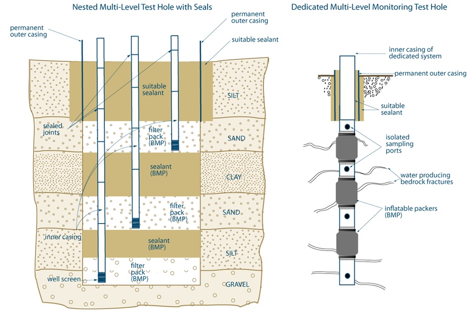
Figure 8-23 shows a cross-sectional diagram of two examples of multi-level monitoring systems that are not scheduled to be abandoned within 180 days after completing the well’s structural stage.
The diagram shows a nested multi-level test hole with seals on the left side of the diagram and a dedicated multi-level monitoring test hole on the right side of the diagram.
On the left side of the diagram, a nested multi-level test hole with seals is constructed through an upper silt, upper sand, clay, lower sand, lower silt and gravel deposits. The nest consists of three casings with well screens attached to the bottom of the casings. The joints on all of the casings have been sealed.
On the left side of the nested multi-level test hole diagram, a casing and well screen extend from above the ground surface to the gravel deposit. As a best management practice, filter pack material is placed around the well screen and the lower portions of the casing. As a best management practice, a layer of sealant is placed above the filter pack to the top of the lower silt deposit.
In the centre of the nested multi-level test hole diagram, a casing and well screen extend from above the ground surface to the lower sand deposit. As a best management practice, filter pack material is placed around the well screen and the lower portions of the centre casing in the lower sand deposit. The filter pack material also fills around the casing on the left side of the diagram. As a best management practice, a layer of sealant is placed around the casings from above the filter pack to the top of the clay deposit.
On the right side of the nested multi-level test hole diagram, a casing and well screen extend from above the ground surface to the upper sand deposit. As a best management practice, filter pack material is placed around the well screen and the lower portions of the right casing in the upper sand deposit. The filter pack material also fills around the casings on the left side and centre area of the diagram. A suitable sealant is placed around the casings from the ground surface to the top of the upper sand deposit.
A permanent outer casing is placed outside of the three casings from above the ground surface to the top of the upper sand in the nested multi-level test hole diagram. The annular space from the top of the permanent outer casing to the bottom of the permanent outer casing is filled with a suitable sealant.
On the right side of the diagram, a dedicated multi-level monitoring test hole is constructed through overburden and into the bedrock. The upper portion of the dedicated system consists of a casing that extends vertically from above the ground surface, through the overburden and into the bedrock. A suitable sealant is placed in the annular space adjacent to the casing from the ground surface to the bottom of the casing. An isolated sampling port is attached to the bottom of the casing in the bedrock. As a best management practice, an inflatable packer is attached to the bottom of the sampling port. Five additional sampling ports and four packers have been attached below the upper packer in the same sequence as with the upper sampling port and packer. The diagram also shows the dedicated multi-level system intersecting water producing bedrock fractures.
A permanent outer casing is placed outside of the dedicated system’s inner casing from above the ground surface, through the overburden and into the bedrock. The annular space from the top of the permanent outer casing to the bottom of the permanent outer casing is filled with a suitable sealant.
- This diagram shows two examples of the many types of multi-level monitoring systems. To operate a new multi-level monitoring test hole longer than 180 days a person must install a permanent outer casing around the dedicated system or inner casings.
- As a best practice, the permanent outer casing should be extend to at least 6 m (19.7') from the ground surface or as close to the top of the upper screen or port internal as possible.
- An annular space must be created around the permanent outer casing and then filled with a suitable sealant as described in this section and in Chapter 7: Annular Space & Sealing.
- A suitable sealant, such as a bentonite product, a cement product or an inflatable packer should be properly placed between ports or well screens, except in the case of a dedicated system that employs a liner.
- If groundwater is entering between the inner casing(s) and the permanent outer casing, the entire annular space from the inner casing(s) to the permanent out casing must be sealed (with necessary modifications). The proper sealing process is described in Chapter 7: Annular Space & Sealing and must be followed unless the new test hole was constructed by the use of a driven point. In all cases, the annular space between the inner casing(s) and permanent outer casing must be sealed with suitable sealant to prevent the entry of surface water and other foreign materials.
Reminder: This figure is not to scale, it is for illustrative purposes for this chapter only and does not necessarily represent full compliance with the requirements found in the Wells Regulation.
Disclaimers
Reminder: The use of brand names in this manual is for identification purposes only and does not constitute an endorsement by the Ministry of the Environment.
Reminder: The information and illustrations of these systems do not constitute a recommendation of any or all of the systems. The table and illustrations are presented solely to provide information on the systems that are currently available and how these systems could be installed to meet the requirements of the Wells Regulation.
Footnotes
- footnote[1] Back to paragraph Nielsen, David, M. 2006. Practical Handbook of Environmental Site Characterization and Groundwater Monitoring: Second Edition. CRC/Taylor & Francis. Boca Raton, FL. P824
- footnote[2] Back to paragraph Nielsen, David M. 2006. Handbook of Environmental Site Characterization and Ground-Water Monitoring. CRC/Taylor and Francis Group. Boca Raton, FL. P836.
- footnote[3] Back to paragraph Nielsen, David M. 2006. Handbook of Environmental Site Characterization and Ground-Water Monitoring. CRC/Taylor and Francis Group. Boca Ratan, FL. Fig 11.10, P829.
- footnote[4] Back to paragraph Schlumberger Water Services, SW Technology
- footnote[5] Back to paragraph Schlumberger Water Services, SW Technology
- footnote[6] Back to paragraph Schlumberger Water Services, SW Technology
- footnote[7] Back to paragraph Schlumberger Water Services, SW Technology
- footnote[8] Back to paragraph Model 401 Data Sheet from Solinst Canada Ltd, Solinst website
- footnote[9] Back to paragraph Waterloo system Model 401 Data Sheet from Solinst Canada Ltd., http://www.solinst.com/Prod/Data/401.pdf
- footnote[10] Back to paragraph CLAIRE Technical Bulletin from Solinst Canada Ltd., http://www.solinst.com/Res/cmt/ClaireTech.pdf
- footnote[11] Back to paragraph footnote here
- footnote[12] Back to paragraph CMTTM Multi-Level System Data Sheet from Solinst Canada Ltd., CMT Multilevel System Assembly Manual
- footnote[13] Back to paragraph CMT™ Multi-Level System Data Sheet from Solinst Canada Ltd., CMT Multilevel System Assembly Manual
- footnote[14] Back to paragraph CMTTM Multi-Level System Data Sheet from Solinst Canada Ltd., CMT Multilevel System Assembly Manual
- footnote[15] Back to paragraph Einarson, Murray D, John A. Cherry. A New Multi-Level Groundwater Monitoring System Utilizing Multi-Channel Tubing.” Groundwater Monitoring and Remediation, 22 No 4, Fall 2002 pages 52 to 65, http://www.solinst.com/Res/cmt/52to65Fall02GWMR.pdf
- footnote[16] Back to paragraph Flexible Liner Technologies, LLC http://www.flut.com/sys_1.html
- footnote[17] Back to paragraph Flexible Liner Technologies, LLC http://www.flut.com/sys_1.html