9. Completing the Test Hole or Dewatering Well Structure
Chapter Description
This chapter covers the requirements and exemptions for the finishing steps of new well construction. Some of the finishing steps include developing, venting, covering and securing a test hole or dewatering well. This chapter also covers the requirements for affixing a well tag to a test hole or dewatering well.
There are other requirements and exemptions for finishing a new well that are not listed in this chapter because they do not relate to the structure of the well. For example a person constructing a test hole or dewatering well must complete a well record or a cluster well record and deliver it to the well purchaser and the owner of the land as required by the Wells Regulation. The well record and other requirements are covered in subsequent chapters.
The requirements listed in this chapter do not apply to shallow works or other exempted wells discussed in Chapter 3: Exemptions: Wells, Activities & Experienced Professionals.
Regulatory Requirements - Completing The Well’s Structure
Relevant Sections - The Wells Regulation
- Well Pit – Subsections 12(7.1), 12(9) paragraphs 1, 2 and 3
- Covering the Well – Section 12.2 and Subsections 15.2(6) to (8)
- Surface Drainage – Section 12.3
- Casing Height – Subsections 13(8), 13(9), 13(10), 13(11) and 13(11.1)
- Development by Surging – Subsection 14.4(2), paragraph 1, i, B
- Development – Subsection 14.8(1)
- Well Tag – Section 14.11 and Subsection 14.11(5)
- Venting – Subsection 15.1(1) and 15.1(2)
- Affixing a Well Tag During Alteration to a Cluster Well – Subsection 16.4(4)
The Requirements - Plainly Stated
The Wells Regulation requires or exempts the following regarding the finishing steps of the construction of a new test hole or dewatering well:
Covering the Well
If the well is left unattended during construction, the person constructing the test hole or dewatering well must cover the upper open end of the well securely to prevent entry of surface water and other foreign materials (see Chapter 12: Equipment Installation for further information on well caps and covers).
Surface Drainage (Earth Mounding) around the Well:
The person constructing the test hole or dewatering well must ensure that the slope of the ground surface (surface drainage) is such that water will not collect or pond near the well. Preventing the collection or ponding of water can be ensured by properly mounding with earth around the well and outward from the well to direct surface water away from the well.
Extent of Casing for New Test Holes and Dewatering Wells in an Overburden Aquifer
Unless exempted, a new test hole or dewatering well that obtains water from an overburden formation must be cased:
- from the water intake zone,
- to at least 40 cm (16 inches) above the highest point on the ground surface within 3 m (10 ft) radially from the outside of the casing after the land is properly mounded for surface drainage as measured on completion of the well’s structural stage.
There are a number of exemptions to these casing requirements which will be discussed on the following pages [e.g., an uncased well, a well constructed by use of a driven point and a well completed with a flush-mounted well pit (vault)].
Extent of Casing for New Test Holes and Dewatering Wells in a Bedrock Aquifer
Unless exempted, a new test hole or dewatering well that obtains water from a bedrock formation must be cased:
- from the bedrock,
- to at least 40 cm (16 inches) above the highest point on the ground surface within 3 m (10 ft) radially from the outside of the casing after the land is properly mounded for surface drainage as measured on completion of the well’s structural stage.
There are a number of exemptions to these casing requirements which will be discussed on the following pages [e.g., an uncased well, a well constructed by use of a driven point and a well completed with a flush-mounted well pit (vault)].
Casing Height Exemption for New Driven Point or Jetted Point Wells
An exemption to the minimum casing height requirement of 40 cm (16 inches) above the ground surface exists if the new well is made by the use of a jetted point or driven point, and it has a visible, permanent marker.
To qualify for this exemption:
- the casing must extend a sufficient height to permit the attachment of a well tag;
- the casing must be at least as high as the highest point on the ground surface within a 3 m (10 ft) radius of the well’s casing after the ground surface is properly mounded with earth to direct surface drainage away from the well as measured on completion of the well’s structural stage; and
- the permanent marker must identify the location of the well and be visible at all times of the year.
In certain circumstances, a test hole or dewatering well may be completely exempt from the casing height requirements discussed above [e.g., an uncased well and a well completed with a flush-mounted well pit (vault)].
Casing Height Exemption for Test Holes and Dewatering Wells Completed with Flush-mounted Well Covers
A test hole or dewatering well is not required to be cased above the ground surface if the:
- well is located where vehicle or pedestrian traffic is likely to pass directly over the well,
- well is completed with a flush-mounted watertight commercially manufactured well cover sufficient to prevent entry of surface water and other foreign materials into the well, and
- well cover is sufficiently strong, durable and well-installed to protect the well from damage, or the well cover is covered with a metal plate that is sufficiently large and strong, durable and well-installed to protect the well cover and the well from damage.
Well Pits
In most circumstances, well pits are not allowed to be constructed on new or existing test holes or dewatering wells.
In certain circumstances, however, a person constructing a new test hole or dewatering well may be allowed to finish the well with a well pit or add a well pit to an existing test hole or dewatering well. The Wells Regulation provides options for the construction of permitted well pits depending on the location of the well, the type of equipment used to construct the well and the well’s purpose.
Reminder: The well pit requirements, including requirements for flush-mounted well pits (vaults), can be found in Chapter 12: Equipment Installation.
Exemption - Well Casing
A test hole or dewatering well is not required to be cased if both of the following conditions exist:
- abandonment of the test hole or dewatering well is scheduled to take place not later than 30 days after completion of the well’s structural stage; and
- the person constructing the well covers the upper open end of the well securely in a manner sufficient to prevent the entry of surface water and other foreign materials whenever the well is left unattended.
Reminder: See Chapter 6: Constructing the Hole, Casing & Covering the Test Hole or Dewatering Well for additional information on uncased test holes or dewatering wells.
Well Caps or Covers
Dug or Bored
The top of the casing of a well that is constructed by digging or boring must be covered with a solid, watertight well cover, so that surface water and other foreign materials cannot enter into the well.
Drilled or Other
The top of the casing of a well that is not constructed by digging or boring must be sealed with a commercially manufactured vermin-proof well cap (this includes a properly installed and sealed sanitary well seal and a watertight and airtight well cap for a point well).
Exceptions - Well Caps or Covers
A cover, cap or seal is not required if all of the following criteria are met:
- A floor has been constructed around or adjacent to the casing of the well.
- A pump (includes associated pump equipment such as a waterline connected to a pump) is installed above or adjacent to the well.
- The top of the casing is shielded in a manner sufficient to prevent entry of any material that may impair the quality of the water in the well.
- The casing of the well is extended to at least 15 cm (6 inches) above the floor that has been constructed around or adjacent to the casing of the well.
Reminder: See Chapter 12: Equipment Installation for further information on well caps and covers.
Exemption - Developing the Test Hole and Dewatering Well
The requirement for developing a new well to remove any debris (such as well cuttings, drilling fluids, etc.) from the well and until the well water is clear and free of sand does not apply to test holes and dewatering wells. However, if a test hole or dewatering well is completed in overburden and will be used for more than 180 days, the gravel or sand around the well screen must be developed, after the placement of suitable sealant, using a surging method to remove fine grained soils.
Venting
When a new dewatering well is constructed, the well must be vented to the outside atmosphere in a manner that will safely disperse all gases unless the casing is used to transmit water out of the well.
Additional venting requirements may apply after pumping equipment is installed in the well.
Exemptions - Venting
The above requirement does not apply to a:
- test hole, or
- dewatering well where the casing will be used to transmit water out of the well (e.g., driven point dewatering system).
Venting requirements may apply if pumping equipment is installed in a well.
Reminder: See Chapter 12: Equipment Installation for further information on venting requirements.
Well Tags
Before the structural stage of a new cased test hole or dewatering well is completed, a well tag from the Ministry must be obtained and affixed permanently to the outside of the casing, or to a permanent structure associated with the well. The affixed well tag must be visible and not hidden by the well cap, any other components of the well or equipment associated with the well.
If an alteration, other than a minor alteration, is made to a cased well that does not already have a well tag, a well tag from the Ministry must be obtained and affixed before the alteration is completed as per the first paragraph of this section.
If a cased well that already has a well tag is altered, the well tag must be safeguarded during the alteration. If the well tag is removed before the alteration is completed, it must be reaffixed as per the first paragraph of this section.
If a broken, defaced, illegible or otherwise unusable well tag is encountered when altering the well, including a minor alteration, the person altering the well must:
- obtain a new well tag from the Ministry and, before the alteration is completed, affix it as per the first paragraph of this section, and
- return the original well tag and a completed well record with respect to the replacement of the well tag to the Director within 30 days after the new well tag is affixed to the casing.
Well Tags for Test Hole and Dewatering Well Clusters
If one well record is completed for a cluster of new wells as permitted by the Wells Regulation, it is only necessary to affix one well tag to the deepest well in the cluster (see Chapter 15 Well Records, Documentation, Reporting & Tagging for further information on well clusters).
Well Tags - Affixing a Well Tag During Alteration to Cluster Wells
If an alteration, other than a minor alteration, is made to a well in the well cluster the person making the alteration must obtain and affix a well tag to the well that has been altered, if it does not already have a well tag.
Reminder: For further information on well tags, see Chapter 15: Well Records, Documentation, Reporting & Tagging.
Records of Site Condition Regulation: Starting on July 1, 2011, amendments to O. Reg. 153/04 came into force and apply to phase two environmental site assessments (ESAs) conducted in support of records of site conditions (RSCs). For any such RSC submitted on or after this date, the following requirements related to well construction apply:
-
where sampling of groundwater is being undertaken to demonstrate if the applicable site condition standard for a contaminant has been met or not, the qualified person must ensure that:
- a monitoring well from which a sample is to be collected has been developed to remove any fluids that may have been introduced into the well during drilling and to remove particulates that may have become entrained in the well and filter pack.
- the well development referred to above is documented by recording:
- the date of the development,
- the time the development started and stopped, and
- the volume of fluid removed from the well during development,
- a rationale for concluding the development was complete, and
- a description of the measures taken to minimize cross-contamination between wells when using non-dedicated equipment, and
- Precautions are taken to minimize the potential for cross-contamination or contamination through preferential pathways.
Records of Site Condition Regulation: There are additional obligations when taking groundwater samples for the purpose stated above. Please refer to O. Reg. 153/04 for the RSC requirements.
Relevant Sections - Additional Regulations or Legislation
- Ontario Water Resources Act – Subsection 30(1)
- Environmental Protection Act – Subsection 14(1)
- Regulation 153/04 as amended (Records of Site Condition)
Relevant Standards
ASTM D 5092-04e1 – "Standard Practice for Design and Installation of Ground Water Monitoring Wells," (DOI: 10.1520/D5092-04E01)
ASTM D 5978-96 (2005) – "Standard Guide for Maintenance and Rehabilitation of Ground-Water Monitoring Wells," (DOI: 10.1520/D5978-96R05)
ASTM D 5787-95 (2009) – "Standard Practice for Monitoring Well Protection," (DOI: 10.1520/D5787-95R09)
ASTM D5521-05 “Standard Guide for Development of Ground-Water Monitoring Wells in Granular Aquifers” (DOI: 10.1520/D5521-05)
Relevant Guidelines
Imperial Oil – Preferred Operating Practices for Borehole/Monitoring Well Installation and Associated Soil/Groundwater Sampling at Hydrocarbon Impacted Sites
US Army Corps of Engineers – Monitoring Well Design, Installation and Documentation at Hazardous, Toxic, and Radioactive Waste Sites
Key Concepts
What to Consider When Completing the Well’s Structure
Purpose of the Test Hole or Dewatering Well
When completing the test hole or dewatering well’s structure, it is important to consider the reason for the well installation. The well’s purpose will impact how the structure should be completed. For example, an uncased test hole used for soil and water table observations must be covered securely in a manner sufficient to prevent the entry of surface water or other foreign materials until it is abandoned. A long-term monitoring well will have to be properly cased and sealed with an appropriate well cap or cover.
Well Development
The purpose of well development is to remove any water or drilling fluids introduced into the test hole or dewatering well during drilling; stabilize the filter pack and formation materials opposite the well screen; minimize the amount of fine-grained sediment entering the test hole or dewatering well; and improve well efficiency and inflow of water into the test hole or dewatering well.
Development of a test hole is important when sampling for water quality or determining hydraulic characteristics of a subsurface formation. Development of a dewatering well maximizes the efficiency of the dewatering system and minimizes the turbidity of the discharge water.
Casing Height and Moundingfootnote 2
A sufficient height of casing above the ground surface, or above the floor of a well pit, helps to prevent the entry of surface water or foreign materials through the top of the well. In addition, mounding earth immediately around the casing helps to direct surface drainage away from the well to reduce the risk of surface water ponding at the well site and to reduce the potential for surface water to migrate down the side of the well casing into the well.
Well Caps, Covers and Securing the Well
Securing and covering the casing are the primary safeguards against unauthorized entry into the well, vandalism or tampering. Wells caps and covers also protect against the movement of surface water or foreign materials from the surface into the well. Securing the well includes ensuring that the well cap, seal or cover is on properly and may include the use of a protective cover with locking cap, barriers or fences.
Well Tag (Identification)
Well identification numbers link wells in the field with written records. The Ministry issues alphanumeric well tags that must be affixed to wells during construction or to at least one well in a well cluster. The well tag will link the well or the well cluster to a corresponding well record. A well tag or number is important as it links detailed information of the construction process and design of the well. This information is crucial to persons who have to:
- locate wells in the field,
- test and sample, or
- maintain, or if necessary, alter or abandon a well.
Well Development
Well development has four broad objectives:
- To remove any water or drilling fluids introduced and fine materials disturbed during the construction of the test hole or dewatering well in order to obtain representative groundwater information and sediment-free water samples. In addition, this will minimize the potential for damaging pump equipment.
- To correct damage to the hole wall and adjacent native geological material caused during construction. This creates natural physical aquifer conditions to help determine hydraulic parameters such as hydraulic conductivity (K).
- To stabilize the filter pack and formation materials opposite the well screen. Development creates a graded zone (i.e., natural sand and/or gravel pack with larger to smaller material away from the water intake zone) around the well screen in an overburden well (see Figure 9-1).
- To maximize the efficiency of the well and hydraulic connection between the well intake zone and the formation by decreasing the potential for lower porosity and permeability near and at the well intake
footnote 3 .
The Wells Regulation exempts test holes and dewatering wells from the requirements of well development. However, if a new test hole or dewatering well, other than a well constructed by digging or by the use of a jetted or driven point, is completed in overburden and will be used for more than 180 days, the gravel or sand around the well screen must be developed, after the placement of suitable sealant, using a surging method to remove fine grained soils.
The Wells Regulation provides an exemption from well development because of the various testing and monitoring needs that are required for many different types of test holes and dewatering wells. For example, there is no practical way to develop a test pit excavation when a person is observing the location of the shallow groundwater and soils.
In many cases, it is important to develop test holes and dewatering wells, however, they are often not properly developed. If the construction process goes according to plan, and the water level appears to recover quickly after drilling, test holes or dewatering wells are often deemed complete. This may be adequate for establishing where the aquifer is located but may not be adequate for water quality sampling or testing of the aquifer’s physical characteristics.
When making a decision whether or not to develop a test hole or dewatering well, the person constructing the well should take into consideration of the following:
- A person constructing a well on a contaminated site should consider the effect that development may have on the contaminated plume.
- A person constructing a well on a contaminated site may want to limit the handling of the development water.
- A person constructing a well may have to consider a potentially significant cost and time associated with the development of a test hole of dewatering well in fine grained formations.
Drilling sediments that have not been properly removed from the well and surrounding formation may bias sample water quality and aquifer testing results leading to improper interpretations and further costs.
Records of Site Condition Regulation: Starting on July 1, 2011, amendments to O. Reg. 153/04 came into force and apply to phase two environmental site assessments (ESAs) conducted in support of records of site conditions (RSCs). For any such RSC submitted on or after this date, the following requirements related to well construction apply:
-
where sampling of groundwater is being undertaken to demonstrate if the applicable site condition standard for a contaminant has been met or not, the qualified person must ensure that:
- a monitoring well from which a sample is to be collected has been developed to remove any fluids that may have been introduced into the well during drilling and to remove particulates that may have become entrained in the well and filter pack.
- the well development referred to above is documented by recording:
- the date of the development,
- the time the development started and stopped, and
- the volume of fluid removed from the well during development,
- a rationale for concluding the development was complete, and
- a description of the measures taken to minimize cross-contamination between wells when using non-dedicated equipment, and
- Precautions are taken to minimize the potential for cross-contamination or contamination through preferential pathways.
Records of Site Condition Regulation: There are additional obligations when taking groundwater samples for the purpose stated above.
Reminder: Please refer to O. Reg. 153/04 for RSC requirements.
Best Management Practice – Test Hole or Dewatering Well Development
Where it is necessary to obtain representative groundwater samples and measurements or the highest well efficiency, a test hole or dewatering well should be properly developed. Proper well development will result in a well that produces water that is representative of conditions in the formation(s) from which the well obtains groundwater.
Monitoring well development should continue until:
- the discharge water is visibly clear,
- the pH, Eh and conductivity field measurements are stable in the discharge water,
- the turbidity is below 10 Formazin Turbidity Units (FTU), and
- the volume of discharge water at least equals the estimated volume of fluid lost during the well construction and installation.
ASTM D5521-05 “Standard Guide for Development of Ground-Water Monitoring Wells in Granular Aquifers
Figure 9-1: An Overburden Drilled Well Developed to a Sand-Free State
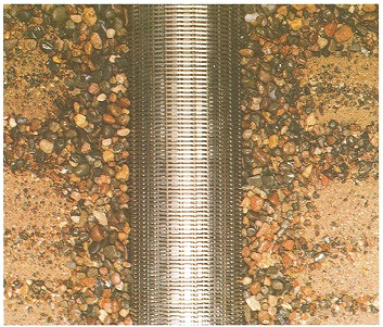
Figure 9-1 shows how development (by surging water back and forth) has created a graded zone (i.e., natural sand or gravel pack with larger to smaller material away from the water intake zone) around the well screen in an overburden well.
Development Methods
There are many different factors that contribute to the method chosen to develop a well. The selection of the appropriate development methods from those listed below must be based on:
- equipment available and accessibility to the well,
- geology and hydrogeology (depth of aquifer in relation to well screen),
- well construction system and method used (cutting action used, flushing media),
- type of well installation (e.g., casing, annular space),
- diameter and depth of well,
- diameter, slot size and length of well screen and filter pack,
- hydraulic characteristics of the well (e.g., static water level),
- health and safety requirements for field staff,
- types of contaminants and proper disposal of discharge water, and
- regulatory requirements (e.g., Permit to Take Water, discharge approval, waste transfer approval).
Well Development Techniques
Below is a list of some methods of well development for various scenarios. In some cases multiple techniques may be used to develop a well. The methods include:
- surging or washing/backwashing with plunger devices (forcing water to flow in and out of a well screen by operating a plunger up and down in the well),
- air lift development (using an air lift to alternately surge and pump the well),
- air burst development (a combination of pumping with air and using large bursts of air injected into the well screen or bedrock hole to surge the formation),
- manual development (using a inertial lift pump),
- jetting (the use of high velocity jetting tools),
- over-pumping with a submersible pump (pumping at a higher rate than the well will be pumped when put into service),
- bailer surging, and
- hydrofracturing (hydrofracing) (bedrock test hole or dewatering well only).
The Wells Regulation - Any water introduced into the well during development or other well construction must not impair the quality of any well water or cause an adverse effect on the natural environment.
Reminder: The container used to transport any water brought to the site for the well development must not contaminate the water in the container.
Reminder: Appropriate precautions should be taken to contain, transport and dispose in an approved manner all contaminated groundwater discharged out of the monitoring well during development.
Surging
Surging is the simplest and the most common method of development. The clay, silt and sand grains are agitated by rapidly moving a plunger up and down in the well. This action moves the water in and out of the formation and well screen as shown in Figure 9-2. Water containing fine granular material moves into the well casing. The granules tend to settle to the bottom of the well so they can be removed by pumping water or air or by bailing.
Figure 9-2: Surging
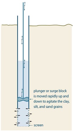
Reminder: This figure is not to scale, it is for illustrative purposes for this chapter only, and does not necessarily represent full compliance with other requirements found in the Wells Regulation.
Air-Lift Pumping
Another method available for developing a test hole or dewatering well is pumping with an air-lift pump at a high rate for a brief period, to draw water and formation fines into the test hole or dewatering well. Then the pump is shut off to “slug” the well, loosening formation fines, and breaking sand bridges in the formation and filter pack.
Other Methods
A common development technique for test holes and dewatering wells with a diameter of 5 cm (2 inches) is to flush the well with water through a clean tremie pipe. Extra care must be taken to maintain the integrity of the well for water quality sampling.
Other monitoring wells of smaller diameter, (e.g., 3.8 cm [1 ½ inches], 3.2 cm [1 ¼ inches], and 2.5 cm [1 inch]) are usually developed using an inertial pumping arrangement such as tubing and a foot valve.
Reminder: Some types of well screen material, such as PVC, may be exposed to excessive amounts of stress if certain development methods or tools (e.g., surge blocks) are used to develop the well. The strength of the well screen material should always be considered when choosing a development method.
Reminder: Further information on well development can be found in ASTM D5521-05 “Standard Guide for Development of Ground-Water Monitoring Wells in Granular Aquifers
Casing Height & Mounding
Surface Drainage (Mounding)
Mounding earth immediately around the casing to direct surface water away from the well helps to reduce the risk of surface water ponding at the well site and to reduce the potential for surface water to migrate down the side of the well casing into the well.
The Wells Regulation - The person constructing the test hole or dewatering well must ensure that the surface drainage is such that water will not pond in the vicinity of the well.
Best Management Practice – Moundingfootnote 7
To prevent pooling of water around the well, the following should be considered:
- In areas subject to frost heave, a soil or bentonite/sand layer should be placed adjacent to the protective cover, sloped to direct water drainage away from the well.
- In areas not subject to frost heave, a concrete pad, sloped slightly to provide water drainage away from the well should be installed.
- Erosion and/or ponding in the immediate vicinity of the monitoring well may be prevented by ensuring that ground surface slopes away from the monitoring well protective casing and by spreading a 150 mm (6 inches) thick, 2.4 m (8 feet) diameter blanket of 19 mm to 75 mm (3/4 inches to 3 inches) gravel around the monitoring well.
Reminder: For information on surface drainage for flush-mounted well pits (vaults) see Chapter 12: Equipment Installation
Reminder: See the Figure 9-6: Common Flush-mounted Well Pits (Vaults) of this chapter for additional information on protective covers.
Casing Height
The casing height must be checked at the completion of the well’s structure to ensure it complies with the Wells Regulation.
The Wells Regulations - Unless exempt, the casing height of a new test hole or dewatering well must be at least 40 cm (16 inches) above the highest point within a 3 m (10 ft) radius of the well’s casing after the ground surface is properly mounded with earth to direct surface drainage away from the well as measured on completion of the well’s structural stage. Figure 9-3 illustrates these measurements.
Reminder: There are exemptions to the above well casing height requirement for a new test hole or dewatering well constructed by the use of a driven point or jetted point or with a well pit. See the “Casing Height for New Point Wells Constructed by Driving or Jetting” section of this chapter, the “Well Pit Floor” section of Chapter 12: Equipment Installation for further information and Chapter 3: Exemptions: Wells, Activities & Experienced Professionals.
The Wells Regulation - If a test hole or dewatering well casing extends to a height of 40 cm (16 inches) or more above the ground surface, the height of the casing cannot be reduced to a height of less than 40 cm (16 inches) above the ground surface. This includes cutting the casing or increasing the elevation of the ground surface adjacent to the well. Therefore, persons who work on equipment in a well, environmental consultants, company employees, developers, general contractors, landscapers and well owners should be aware of the minimum height of the well casing requirement above the ground surface. If the ground surface is raised, then the owner of the land or a properly licensed person working on the well must extend the well casing to the minimum required height.
The Wells Regulation - The height requirement immediately above does not apply to a driven or jetted point well that meets the casing height and other requirements described on the Casing Height for New Point Wells Constructed by Driving or Jetting section of this chapter. This requirement also does not apply to a test hole or dewatering well that meets the Wells Regulation requirements for a well completed with a flush-mounted well cover as described on the Casing Height Exemption for Test Holes and Dewatering Wells Completed With Flush-Mounted Well Covers section of this chapter.
Reminder: The regulatory exemptions regarding test holes and dewatering wells allow for well technicians, engineers and geoscientists to use their professional expertise to design and install test holes and dewatering wells on a case by case basis.
Reminder: If work must be performed to raise the well casing, the person hired to do the work must have, or work for a business that has, a valid well contractor licence and have the proper prescribed class of well technician licence. See Chapter 4: Well Contractors & Well Technicians – Licences, Responsibilities & Exemptions for further information.
Figure 9-3: How to Measure Casing Height Above the Ground Surface for a New Well (Other than a Well Constructed by the Use of a Jetted Point and/or Driven Point with a Permanent Visible Marker Identifying the Well)
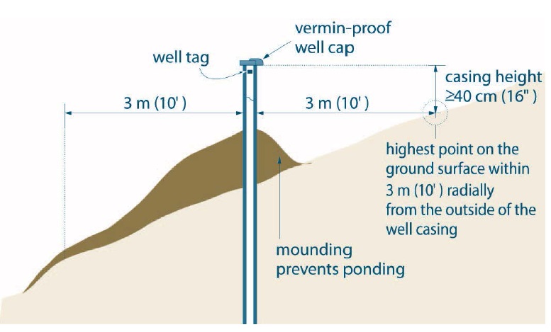
Figure 9-3: How to measure casing height above the ground surface for a new well (other than a well constructed by the use of a jetted point and/or driven point with a permanent visible marker identifying the well)
The figure is a cross-sectional view of a well on the side of a sloped terrain, where the ground surface is highest on the right and lowest on the left. The well is roughly located on the middle of the slope. A vermin-proof well cap is installed on the top of the well, with a well tag is affixed to the casing just below the well cap. There is mounded earth around the well casing, with the label “mounding prevents ponding”. There are measurements shown to identify that the casing height above ground must be greater than or equal to forty centimeters (or sixteen inches) from the highest point on the ground surface, shown on this figure as being on the right, within three metres (or ten feet) radially from the outside of the well casing.
This figure is not to scale, it is for illustrative purposes for this technical bulletin only and does not necessarily represent full compliance with other requirements found in the Wells Regulation.
Reminder: The same method of measuring casing height applies to new jetted and driven point wells that have been constructed with a permanent visible marker. In that case, the casing must extend a sufficient height to permit the attachment of the well tag and be at least as high as the highest point on the ground surface within 3 m (10ft) radially from the well.
Reminder: This figure is not to scale, it is for illustrative purposes for this chapter only, and does not necessarily represent full compliance with other requirements found in the Wells Regulation.
Casing Height When Multiple Casings are Used in a Test Hole or Dewatering Well
In some cases, multiple casings of different diameters are installed in a test hole or dewatering well to reach a water producing zone. Unless exempt, at least one of the casings has to meet the height requirements in the Wells Regulation.
The Wells Regulation - In the case of a multi-level test hole with an outer permanent casing and multiple inner casings:
- all casing extending from well screens must meet the height requirements in the Wells Regulation as described in the “Plainly Stated” section of this chapter, or
- the outer permanent casing must meet the height requirements in the Wells Regulation as described in the “Plainly Stated” section of this chapter.
Reminder: See Chapter 6: Constructing the Hole, Casing & Covering the Test Hole or Dewatering Well, Chapter 7: Annular Space & Sealing and Chapter 8: Multi-Level Monitoring Test Holes for further information on the installation of multi-level test holes.
Casing Height for New Point Wells Constructed by Driving or Jetting
The Wells Regulation - An exemption to the minimum casing height requirement of 40 cm (16 inches) above the ground surface exists if the new well is made by the use of a jetted point or driven point, and it has a visible, permanent marker.
In these cases, the casing must:
- extend a sufficient height to permit the attachment of a well tag, and
- be at least as high as the highest point on the ground surface within a 3 m (10 ft) radius of the well’s casing for any new well after ground surface is properly mounded with earth to direct surface drainage away from the well as measured on completion of the well’s structural stage.
The permanent marker must also identify the location of the well and be visible at all times of the year.
Best Management Practice – Casing Height
Where feasible, casing height for a test hole or dewatering well should go beyond the minimum casing height requirements, particularly in an area prone to flooding, such as a flood plain. This will also allow for easier maintenance and identification purposes especially for driven and jetted point wells.
The person constructing the well should consider a sufficient casing height to vent gas from a well safely and keep the top of the casing above the top of the static water level in a flowing well.
To ensure a sufficient height of casing above the ground surface, the person constructing the test hole or dewatering well should consider the proposed final grade of the property after landscaping.
When extending the casing of a jetted or driven point well above the ground surface, the person constructing a point well should take the necessary steps in the design and installation to prevent water from freezing within the point well system.
Casing Height Exemption for Test Holes and Dewatering Wells Completed With Flush-Mounted Well Covers
The Wells Regulation - Where the well is located in an area where vehicle or pedestrian traffic is likely to pass directly over the well, the well can be completed with a flush-mounted watertight commercially manufactured well cover that must be:
- sufficient to prevent entry of surface water and other foreign materials into the well, and
- sufficiently strong, durable and properly installed to protect the well from damage, or the cover must be covered with a metal plate that is sufficiently large and sufficiently strong, durable and properly installed to protect the well cover and the well from damage.
There are various ways to complete a well with a flush-mounted well cover. Two examples are shown in Figure 9-4 and Figure 9-5. In these two cases, depending on the type of well, the well cover must meet the requirements for a vermin-proof well cap or solid, watertight well cover.
Also, there are commercially available assemblies commonly referred to as flush-to-grade well vaults, well vaults or flush-mounted well pits which meet the requirements for a flush-mounted well cover. This type of completion is set into the surface seal before it has cured and is installed around the well casing, which has been cut off below grade and properly capped or covered.
To assist the industry, this manual describes a well vault as a “flush-mounted well pit (vault)”. Further clarification is provided in Table 2-3 of Chapter 2: Definitions & Clarifications under the terms “well pit” and “flush-mounted watertight commercially manufactured well cover”.
Reminder: For additional information, requirements and diagrams on well caps, well covers and flush-mounted well pits (vaults), see Chapter 12: Equipment Installation.
Figure 9-4: An Example of a Flush-Mounted Watertight Commercially Manufactured Well Cover
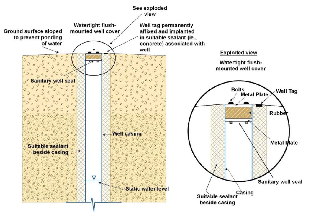
The figure is of a cross-sectional view of the top half of a well, installed flush to the ground surface. The ground surface has a subtle downward slope to prevent ponding of water. The well casing is flush to the ground surface and is surrounded by a suitable sealant. The static water level is shown to be within the lower half of the casing.
At the top of the casing a sanitary well seal. The sanitary well seal is also considered a watertight flush-mounted well cover. Beside the seal, permanently implanted in suitable sealant (i.e., concrete) is the well tag. There is an exploded view of the sanitary well seal and well tag.
Exploded View: The exploded view is a close-up illustration of the top of the well, including the casing, the sealant, the watertight flush-mounted well cover (sanitary well seal), and well tag. The sanitary well seal consists of a metal plate at ground surface, with a rubber middle section, while a second metal plate is below the rubber providing a sanitary seal. Bolts hold the three pieces of the seal together.
Reminder: For new wells, the hole diameter and suitable sealant must meet the minimum requirements found in Chapter 7: Annular Space & Sealing, Tables 7-1A & 7-1B.
Reminder: The well cover, in this case a sanitary well seal, must be sufficiently strong, durable and well-installed to protect the well from damage. The well cover must be commercially manufactured and must prevent the entry of surface water and other foreign materials into the well. The cover should be fastened to prevent tampering.
Reminder: If the cover is placed onto a well that has been constructed by boring or digging, then the cover must be solid, watertight and sufficient to prevent the entry of surface water and other foreign materials into the well. If the cover is placed onto a well that has not been constructed by boring or digging, then the cover must be a commercially manufactured vermin-proof well cap.
Reminder: The casing should be strong enough and properly seated and sealed into the ground to withstand the weight of any person or vehicle and to prevent the casing from sinking into the ground.
Reminder: This figure is not to scale, it is for illustrative purposes for this chapter only and it does not necessarily represent full compliance with other requirements found in the Wells Regulation.
Figure 9-5: An Example of a Flush-Mounted Watertight Commercially Manufactured Well Cover with Metal Plate for a New Well
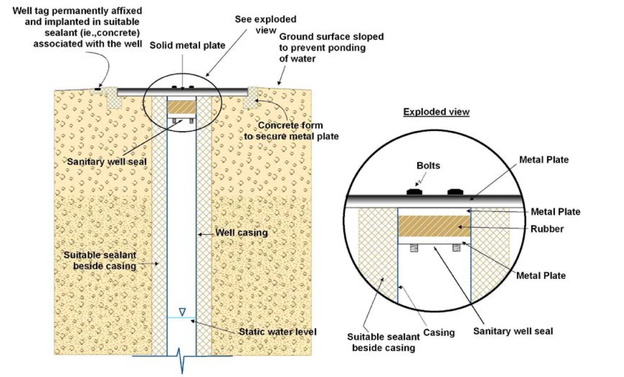
Figure 9-5: An example of a flush-mounted watertight commercially manufactured well cover with metal plate for a new well
The figure is of a cross-sectional view of the top half of a well, installed to just below the ground surface. A solid metal plate sits above the well, with the metal plate being installed to approximately ground surface. The ground surface has a subtle slope with the ground surface on either side of the well being lower than the metal plate covering the well. There is a label pointing to the ground surface that reads “Ground surface sloped to prevent ponding of water”. The well casing is set just below ground surface and is surrounded by a suitable sealant. The static water level is shown to be within the lower half of the casing.
At the top of the casing is a solid metal plate. The metal plate is about twice as wide as the borehole, and extends over the casing, sealant, and into the native soil. The edge of the metal plate is set into a concrete form to secure the metal plate in place. The metal plate has bolts through the top which connect it to the sanitary well seal below. To the left of the metal plate, at ground surface, is a well tag permanently affixed and implanted in the concrete form installed to secure the metal plate. There is an exploded view of the sanitary well seal and metal plate.
Exploded View: The exploded view is a close-up illustration of the top of the well, including the casing, the sealant, the sanitary well seal and flush-mounted metal plate. A metal plate is located at the ground surface. Below the metal plate, is a sanitary well seal. The sanitary well seal consists of an upper metal plate, with a rubber gasket middle and a lower second metal plate. Bolts connect all metal plates and the rubber gasket middle.
Reminder: For new wells, the hole diameter and suitable sealant must meet the minimum requirements found in Chapter 7: Annular Space & Sealing, Tables 7-1A & 7-1B.
Reminder: A well cover, in this case a sanitary well seal, is placed atop the well casing. The sanitary well seal has been covered with a larger metal plate that is sufficiently large and sufficiently strong, durable and well-installed to protect the well cover and the well from damage. The metal plate has been bolted into the sanitary well seal. The well cover must be commercially manufactured and must prevent the entry of surface water and other foreign materials into the well. The cover should be fastened to prevent tampering.
As another option, a sanitary well seal could be placed directly atop the well casing. The well seal could be covered with a larger metal plate that is not affixed to the well seal.
Reminder: If the cover is placed onto a well that has been constructed by boring or digging, then the cover must be solid, watertight and sufficient to prevent the entry of surface water and other foreign materials into the well. If the cover is placed onto a well that has not been constructed by boring or digging, then the cover must be a commercially manufactured vermin-proof well cap.
Reminder: The casing should be strong enough and properly seated and sealed into the ground to withstand the weight of any person or vehicle and to prevent the casing from sinking into the ground.
Reminder: This figure is not to scale, it is for illustrative purposes for this chapter only and it does not necessarily represent full compliance with other requirements found in the Wells Regulation.
Best Management Practice – Completing the Top of the Casing for a Flush-Mounted Well
Where vehicle or pedestrian traffic is likely to pass directly over a test hole or dewatering well, a properly designed commercially manufactured flush-mounted well pit (vault) assembly should be used to complete the top of the well. These assemblies are commonly available and specifically designed to withstand loads associated with vehicle or pedestrian traffic.
For additional information, requirements and diagrams related to flush-mounted well pits (vaults), see Chapter 12: Equipment Installation.
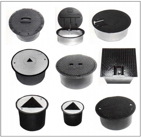
Figure 9-6: Common Flush-Mounted Well Pits (Vaults)
Well Covers and Securing the Well
Covering the Well
The Wells Regulation requires that if the test hole or dewatering well is left unattended during construction, the person constructing the well must cover the upper open end of the well securely in a manner sufficient to prevent the entry of surface water and other foreign materials
Reminder: See Chapter 12: Equipment Installation for further information on well caps and covers.
The Wells Regulation - For a new test hole or dewatering well that is not required to be cased because it is scheduled to be abandoned within 30 days of completion of its structural stage, the person constructing the well must cover the upper open end of the well securely in a manner sufficient to prevent the entry of surface water and other foreign materials.
Dug or Bored
The Wells Regulation - The top of the casing of a well that is constructed by digging or boring must be covered by the person constructing the well with a solid, watertight well cover sufficient to prevent the entry of surface water and other foreign materials into the well.
Reminder: A flat cover with an access lid embedded in the cover is not considered to be watertight. A well cover, such as a one piece solid concrete well cover, is considered to be solid and watertight if it is constructed and installed in a manner sufficient to prevent the entry of surface water and other foreign materials into the well. For clarification on the term “watertight” see Table 2-3 of Chapter 2: Definitions & Clarifications.
Reminder: See Chapter 12: Equipment Installation for graphics and further details on caps and covers.
Drilled or Other
The Wells Regulation - The top of the casing of a well that is not constructed by digging or boring must be sealed by the person constructing the well with a commercially manufactured vermin-proof well cap. This includes a properly installed and sealed sanitary well seal commonly used in wells located in well pits and pump houses. This also includes a watertight and airtight well cap for a well that is constructed with the use of a well point.
Reminder: See Chapter 12: Equipment Installation for graphics and further details on caps and covers.
Well Cap Exemption for Drilled or Other
The Wells Regulation - Every well, other than a dug or bored well must be fitted with a commercially manufactured vermin-proof well cap, unless all of the following criteria are satisfied:
- a floor has been constructed around or adjacent to the casing of the well,
- the casing of the well is extended to at least 15 cm (6 inches) above the floor that has been constructed around or adjacent to the casing of the well,
- a pump is installed above or adjacent to the well, and
- the top of the casing is shielded in a manner sufficient to prevent entry of any material that may impair the quality of the water in the well.
Reminder: See Chapter 12: Equipment Installation for graphics and further details on caps and covers.
Securing the Test Hole or Dewatering Well
Securing the well includes ensuring that the well cap, seal or cover is on properly and may include the use of a protective cover with locking cap (see Figure 9-7), barriers or fences.
Best Management Practice – Use of Protective Cover for a Test Hole Finished Above Ground
A test hole that is finished above the ground surface should have a lockable steel protective cover anchored in a concrete mound around the base. The protective cover should consist of a section of larger width pipe and be placed over the upper end of a smaller diameter monitoring well riser (or casing):
- to provide structural protection to the well,
- to prevent damage to the well, and
- to restrict unauthorized access into the well.
The protective cover should:
- extend from below the depth of frost penetration [typically the frost penetrates 1 m to 1.5 m (3 ft to 5 ft) below ground surface, depending on the local conditions],
- extend to slightly above the top of the well casing [typically, the top of the protective casing should be 15 cm (6 inches) above the top of the well casing to accommodate sampling equipment],
- be initially installed into the annular space sealant before it has set,
- be initially installed before placing the surface seal grout,
-
be sealed and immobilized in a surface seal created by placing either:
- concrete around the outside of the protective casing above the set grout (suitable sealant), or
- dry bentonite pellets, granules or chips in the annular space below ground level and a layer of coarse sand or pea gravel placed above the bentonite in areas prone to frost heave;
- be stabilized in the ground and centered around the well’s casing and
- have a watertight locking lid to prevent water from entering the protective casing.
If concrete is used to seal the base of the protective cover into the ground, the concrete should not be placed on the inside of the protective cover above the ground surface to reduce the risk of damage to the casing (e.g., PVC) during a period of frost heave. The protective cover should be free to move without causing any disturbance to the test hole or dewatering well casing.
Figure 9-7: Test Hole with Protective Cover and Lock
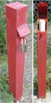
Figure 9-7 shows two photographs of a test hole with a protective cover. In the left photograph, the red protective cover extends out of the ground. A steel lock has been placed on the protective cover. The lockable cover protects the test well’s casing and reduces the chance of unauthorized access or vandalism to the test hole. In the right photograph, the lock and lid on the protective cover have been removed exposing the top of the white PVC plastic casing. In this case, a proper well cap or well cover was not placed on top of the PVC casing as required by the Wells Regulation. Even though the protective cover assists in protecting the well from damage or vandalism, it is not watertight or vermin proof to prevent the entry of flood water or insects into the protective cover and then the well. To resolve this problem, it is important to install a proper well cap or cover on the casing to the requirements of the Wells Regulation. Also, the person installing the cover has not ensured proper surface drainage contrary to the Wells Regulation. The flat ground can allow for surface water to pond at the well site and potentially migrate down the well casing.
Reminder: See Chapter 12: Equipment Installation for graphics and further details on caps, covers and securing the well.
Venting the Well
The Wells Regulation - When constructing a new dewatering well where water is transmitted out of the well with pumping equipment, the person constructing the well must ensure that the well is vented to the outside atmosphere so that all gases will safely disperse from the well. Additional venting requirements may apply after pumping equipment is installed in the well.
Venting does not apply to a new test hole or a new well in which the casing is used to transmit water out of the well (e.g., a drive point dewatering system or a flowing well would be exempt). Venting requirements may apply if pumping equipment is installed in a well.
The purpose of the vent is to allow the well to breathe, which enables pressures to equalize (e.g., when water is drawn out, air can enter the well keeping the column of water at atmospheric pressure). The vent also allows for dispersal of natural gases to the outside atmosphere. In many cases, a properly designed vent is required to be installed on a well to safely disperse a gas that is poisonous, explosive or otherwise hazardous.
Reminder: See Chapter 12: Equipment Installation for additional information on venting requirements.
Special Considerations for Venting
Flowing Wells
Flowing wells are not exempt from the regulatory requirement for venting unless the casing is used in some form to transmit water out of the well or the well is a test hole.
A mechanical or inflatable packer, with a check valve to allow air into and out of the well during pumping, may be installed to vent the well.
Wells Encountering Gas
The Wells Regulation - Where a test hole or dewatering well is constructed and natural gas is encountered, the person constructing the well must notify the well purchaser, the owner of the land, and the Director that the condition exists.
If a well is producing a natural gas or other gas, the well owner must:
- take the necessary steps to manage the gas in a way that prevents any potential hazards,
- properly abandon the well, or
- seek the written consent from the Director to allow for the continued use of the well.
Reminder: Special precautions and procedures will be important when constructing test holes or dewatering wells on a waste site where gases are expected. Gases will need to be managed in a manner sufficient to prevent hazards. See the “Encountering Gas, Contamination and Water Quality” section of Chapter 6: Constructing the Hole, Casing & Covering the Test Hole or Dewatering Well for further information and best management practices dealing with natural gas.
Well Tags
Well Tags for Test Hole or Dewatering Wells Not in Well Clusters
The Wells Regulation requires that, before the structural stage of a new cased well is completed, a well tag from the Ministry be obtained and affixed permanently to the outside of the casing or to a permanent structure associated with the well. The affixed well tag must be visible and not hidden by the well cap and any other components or equipment associated with the well [e.g., protective well cover or flush-mounted well pit (vault)].
The Wells Regulation - If an alteration, other than a minor alteration, is made to a cased well without a well tag, the person making the alteration must obtain and affix a Ministry well tag, as described above, before the alteration is completed.
The Wells Regulation - If a cased well that already has a well tag is altered, the well tag must be safeguarded during the alteration. If the well tag is removed before the alteration is completed, it must be reaffixed, as described above.
The Wells Regulation - If an alteration, including a minor alteration, is made to a well with a well tag that is broken, defaced, illegible or otherwise unusable, the person making the alteration must:
- obtain a new well tag from the Ministry and, before the alteration is completed, affix it to the well casing or a structure associated with the well, and
- return the original well tag and a completed well record with respect to the replacement of the well tag to the Director within 30 days after the new well tag is affixed to the casing.
Reminder: See Chapter 15: Well Records, Documentation, Reporting & Tagging for further information.
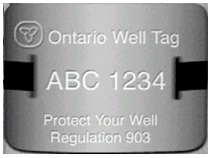
Figure 9-8: Sample of Well Tag
Well Tags for Test Hole or Dewatering Well Clusters
The Wells Regulation - If one well record is prepared for a well cluster, the Wells Regulation allows the person constructing the wells to affix a well tag to only the deepest test hole or dewatering well out of a group of wells as described in the previous section “Well Tags”.
The Wells Regulation requires that the person constructing (altering) a well affix a new well tag to a test hole or dewatering well when an alteration (other than a minor alteration) is made to a well that does not already have a well tag and that is part of a well cluster. The well tag must be affixed to the well as described in the previous section “Well Tags”.
Reminder: A new well record may also be required for the alteration.
Reminder: For further information on tagging and completing well records for a well cluster, please see Chapter 15: Well Records, Documentation, Reporting & Tagging and the definitions of “well cluster” and “minor alteration” in Chapter 2: Definitions & Clarifications Table 2-1.
Footnotes
- footnote[1] Back to paragraph ASTM International, West Conshohocken, PA, 2004, .DOI: 10.1520/D5521-05. ASTM International Website.
- footnote[2] Back to paragraph ASTM Standard 5092-04e1 – "Standard Practice for Design and Installation of Ground Water Monitoring Wells," ASTM International, West Conshohocken, PA, 2004, DOI: 10.1520/D5092-04E01, ASTM International Website. Section 8.91 Protective Casing, p 14.
- footnote[3] Back to paragraph Nielsen, David M. 2006. Neilson Practical Handbook for Environmental Site Characterization and Groundwater Monitoring. Taylor & Francis, Boca Raton, Florida. Pages 850-851.
- footnote[4] Back to paragraph ASTM D5521-05 “Standard Guide for Development of Ground-Water Monitoring Wells in Granular Aquifers” ASTM International, West Conshohocken, PA, 2004, .DOI: 10.1520/D5521-05. ASTM International Website.
- footnote[5] Back to paragraph Sterrett, Robert J. 2007. Groundwater and Wells; Third Edition. Johnson Screens/a Weatherford Company. New Brighton, MN. Figure 11.3, Page 505.
- footnote[6] Back to paragraph ASTM D5521-05 “Standard Guide for Development of Ground-Water Monitoring Wells in Granular Aquifers,” ASTM International, West Conshohocken, PA, 2004, .DOI: 10.1520/D5521-05. ASTM International Website.
- footnote[7] Back to paragraph ASTM 5092-04e1. "Standard Practice for Design and Installation of Ground Water Monitoring Wells." ASTM International, West Conshohocken, PA, 2004, DOI: 10.1520/D5092-04E01, ASTM International Website. 2004: s. 8.9.2, p. 15.