14. Test Hole & Dewatering Well Maintenance & Repair
Chapter Description
This chapter provides the Wells Regulation’s maintenance requirements and recommended measures to prevent the entry of surface water and other foreign materials into a test hole or dewatering well and a well owner’s responsibility to meet these requirements. The chapter also provides the requirements for well owners and persons who work at the construction (or alteration) of existing wells. The requirements listed in this chapter do not apply to shallow works, other exempted wells or the exempted activities discussed in Chapter 3: Exemptions: Wells, Activities & Experienced Professionals.
To assist well owners in meeting their obligations, this chapter discusses various elements of a test hole or dewatering well maintenance program.
Regulatory Requirements - Maintenance
Relevant Sections - The Wells Regulation
- Maintenance – Subsections 20(1), (2) and (3)
- Abandonment – Section 21, Subsections 21(3), (6) to (9)
- Protection of Well Tag – Sections 14.11 and 22
The Requirements - Plainly Stated
The Wells Regulation requires the following:
Well Maintenance
The well owner must maintain the well at all times after the completion of the well’s structural stage in a way that prevents surface water and other foreign materials from entering the well.
Maintaining Casing Height Above the Ground Surface
For a well having a casing height that extends greater than or equal to 40 cm (16 inches) above the ground surface, a person must not reduce the height to less than 40 cm (16 inches) above the ground surface.
For an existing well having the top of the casing extending above the ground surface by less than 40 cm (16 inches), a person must not reduce the original casing height.
Exemption - Maintaining Casing Height for Driven Point or Jetted Point New Wells
An exemption to the minimum casing height requirement above the ground surface exists if the well is made by the use of a jetted point or driven point and it has a visible, permanent marker.
To qualify for this exemption:
- the casing must extend a sufficient height to permit the attachment of a well tag,
- the casing must be at least as high as the highest point on the ground surface within a 3 m (10ft) radius of the well’s casing after the ground surface is properly mounded with earth to direct surface drainage away from the well as measured on completion of the well’s structural stage, and
- the permanent marker must identify the location of the well and be visible at all times of the year.
Exemption - Maintaining Casing Height for a Test Hole or Dewatering Well Completed with a Flush-mounted Well Cover
If the test hole or dewatering well is completed with a flush-mounted watertight commercially manufactured well cover, the casing height requirements listed above do not apply. An existing test hole or dewatering well can be altered to accommodate a flush-mounted well cover as long as all Wells Regulation requirements for the use of this type of cover are met (see Chapter 9: Completing the Test Hole or Dewatering Well Structure and Chapter 12: Equipment Installation for further information).
Well Abandonment
The well owner must immediately abandon the test hole or dewatering well if the well is not being used or maintained for future use as a well.
The well owner must immediately abandon the test hole or dewatering well if the required measures or steps are not taken to address the following issues:
- the well contains natural gas or other gas, or
- the well permits any movement of natural gas, contaminants or other materials between subsurface formations or between any subsurface formation and the ground surface, and the movement may impair the quality of any waters.
The well owner must immediately abandon the well if the well is constructed in contravention of the Wells Regulation requirements and the steps taken by the well owner to rectify the situation fail.
The person abandoning a well may seek the Director’s written exemption from the requirement to abandon the well in some circumstances.
Reminder: For further information see Chapter 16: Abandonment: When to Plug & Seal Test Holes & Dewatering Wells.
Well Tags
A person must not remove a well tag from a test hole or dewatering well unless:
- the well is being altered,
- the well is being abandoned, or
- the Director has given written consent for well tag removal.
If a well tag is removed during an alteration, the well tag must be safeguarded and re-affixed after the alteration has been completed.
No person shall deface, alter, conceal or obstruct an affixed well tag.
Any damaged well tags must be returned to the Ministry and be replaced.
Reminder: See Chapter 15: Well Records, Documentation, Reporting & Tagging for further information.
Reminder: See the “Well Repair Requirements for Persons Constructing Wells” section of this chapter for information on the requirements that apply for an “alteration” (including a repair) to a well.
Reminder: The requirements listed in this chapter do not apply to shallow works, other exempted wells or the exempted activities discussed in Chapter 3: Exemptions: Wells, Activities & Experienced Professionals. However, any construction activity on a test hole or dewatering well must not cause or have the potential to cause impairment to the water in the well or the groundwater as required under Subsection 30(1) of the Ontario Water Resources Act.
Relevant Sections - Additional Regulations or Legislation
- Ontario Regulation 164/99 (Electrical Safety Code) as amended made under the Electricity Act, 1998, S.O. 1998. Chapter 15, Schedule A
- Ontario Regulation 632/05 (Confined Spaces) as amended made under the Occupational Health and Safety Act, R.S.O. 1990, Chapter 0.1
Relevant Standards
ASTM D5978-96 (2005) – “Standard Guide for Maintenance and Rehabilitation of Ground-Water Monitoring Wells,” (DOI: 10.1520/D5978-96R05). ASTM International, West Conshohocken, PA. ASTM International Website.
Relevant Guidance Documents
- Imperial Oil. 2002. Preferred Operating Practices for Borehole/Monitoring Well Installation and Associated Soil/Groundwater Sampling at Hydrocarbon Impacted Sites. Revision 5.
- US Army Corps of Engineers. 1998. Monitoring Well Design, Installation and Documentation at Hazardous, Toxic, and Radioactive Waste Sites (EM 1110-1-4000)
- Fleming College – The Safety Manual for Well Technicians. Fleming College School of Continuing Education – supplemental course material. 2008
- Ontario Ministry of Transportation. April, 2003. Occupational Health and Safety Field Guidelines for Engineering Functions
Key Concepts
Test holes and dewatering wells, like any equipment or structure, have a limited lifespan. Test holes and dewatering wells need preventative maintenance to:
- avoid well performance deficiencies,
- avoid water quality sample biases, and
- maximize the lifespan of the well.
The Wells Regulation states that the well owner must maintain the well at all times after the completion of the well’s structural stage (i.e., once it is capable of being used for the purpose for which it was constructed) in a way that prevents the entry of surface water and other foreign materials into the well.
Proper well maintenance helps to protect the aquifer and the water supply.
Best Management Practice – Minimizing Impact on Groundwater Quality
Well maintenance activities should not alter the chemistry of the groundwater on a site where groundwater quality is being monitored
Improper Well Maintenance
A poorly maintained, constructed or designed test hole or dewatering well can result in the bacterial and/or chemical contamination of groundwater and cross-contamination of other aquifers. Typical concerns with test holes and dewatering wells include:
- pathways through an improperly sealed annular space,
- direct access for contaminants and surface water through non-watertight flush-mounted well pits (vaults) or other well pits, and
- direct access for contaminants through openings in the cover, casing, improperly sealed casing joints or missing covers.
Once problems are encountered with a test hole or dewatering well, it may be possible to rehabilitate it, but this is not always the case. Well owners should be aware that there are many instances when improper maintenance, disuse or the presence of natural gas may require a well to be abandoned in accordance with the Wells Regulation (See Chapter 16: Abandonment: When to Plug & Seal Test Holes & Dewatering Wells and Chapter 17: Abandonment: How to Plug & Seal Test Holes & Dewatering Wells.
The Maintenance Program
The maintenance program is a plan or protocol that should be in place for any site with test holes or dewatering wells. The maintenance program is intended to identify issues and potential problems and rectify these as soon as possible.
Well Repair Requirements for Persons Constructing Wells
In cases where issues or problems are identified with a test hole or dewatering well, it will be necessary to rectify the issues by repairing (e.g., altering, developing) the well to ensure that it does not act as a pathway for contamination, and that it remains suitable for its purpose (e.g., sampling ambient groundwater or dewatering to lower the groundwater level).
There are minimum requirements and exemptions under the Wells Regulation that apply for repairing or altering test holes and dewatering wells. See the later “Well Repair Requirements for Persons Constructing Wells” section of this chapter for further information.
Safety Considerations when Maintaining Wells
There are risks associated with well construction and maintenance activities including explosive gases and electrocution. Since most well owners are not familiar with these potential hazards, licensed well technicians or registered professionals (P. Eng, P. Geo, C.E.T.), knowledgeable about these hazards, should always be hired to work on the well.
Improper Well Maintenance
The Wells Regulation states that the well owner must maintain the well at all times after the completion of the well’s structural stage (i.e., once it is capable of being used for the purpose for which it was constructed) in a way that prevents the entry of surface water and other foreign materials into the well.
The photographs in Figures 14-1 to 14-22 provide examples of improperly maintained or neglected test holes or dewatering wells. In these cases, surface water, contaminants and other foreign materials can enter the well causing bias in sample results, groundwater mounding and impairment of the groundwater quality. Groundwater mounding can alter groundwater flow and contamination patterns and lead to improper interpretations. It is the well owner’s legal obligation to either rectify the problem or properly abandon the well.
Pathways Leading to Contamination
Figure 14-1: Casing Cut at Ground Surface
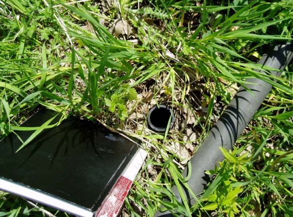
Figure 14-1 shows a small diameter test hole in the centre of the photograph. A portion of the black plastic casing above the ground surface has been cut off at the ground surface and left on the ground to the right of the test hole. There is no cover on the well casing. The opening allows the well to act as a direct pathway for surface water, contaminants and other foreign materials to enter the well. The opening can also allow gases to escape from the well and create an explosive or a poisonous situation near the well.
Figure 14-2: Improper Well Cover in Flush-Mounted Well Pit (Vault)
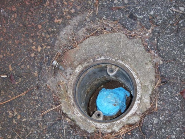
Figure 14-2 shows a flush-mounted well pit (vault) with the cover removed. Within the pit (vault), a blue nitrile glove is used to cover a test hole. The nitrile glove is not sealed to the well. The bottom of the pit (vault) is not sealed. Surface water and other foreign materials can enter through the bottom of the well pit (vault). Once in the pit, surface water, contaminants or other foreign materials can enter the well through or below the glove.
Figure 14-3: Improper Well Cover In Flush-Mounted Well Pit (Vault)
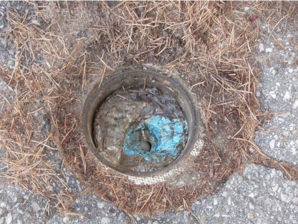
Figure 14-3 shows a similar situation to Figure 14-2. However, a hole has developed in the glove. The opening allows surface water and contaminants to enter directly into the test hole. Figure 14-3 also shows the top of the pit (vault) finished below the asphalt surface. Surface water and other foreign materials can pond on top of the pit (vault) and potentially migrate into the pit (vault).
Figure 14-4: Improper Well Cover In Flush-Mounted Well Pit (Vault)
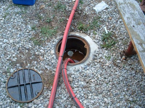
Figure 14-4 shows a flush-mounted well pit (vault) with the cover removed. Within the well pit (vault), a red drop pipe has been removed from a dewatering well. The dewatering well is part of a pump and treat system. The other section of the red pipe moves through the pit (vault) to a pumping system (not shown). Surface water has entered the pit (vault) and is ponding just below the open top of dewatering well’s white plastic casing. Cigarette butts are also floating on top of the surface water. Surface water, contaminants or other foreign materials that have gained access to the pit (vault) can directly enter the well.
Figure 14-5: Sunken Flush-Mounted Well Pit (Vault)
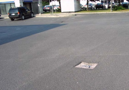
Figure 14-5 shows a flush-mounted well pit (vault) that has sunk below the paved surface of the parking area of a gasoline station due to the weight of vehicle traffic. The vault has also been moved out of plumb. The movement of the pit (vault) has cracked the annular seal (see Figure 14-6). Surface water containing petroleum contaminants and other foreign materials can collect and pond in the vicinity of the pit (vault), move through the broken annular seal and into the monitoring well.
Figure 14-6: Sunken Flush-Mounted Well Pit (Vault)
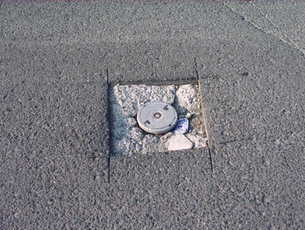
Figure 14-6 shows a close-up view of the sunken well pit in Figure 14-5.
Figure 14-7: No Cover on Dewatering Well
Figure 14-7 shows the galvanized corrugated casing of a dewatering well extending out of the ground on right side of the photograph. The dewatering well is part of a pump and treat system. The seams in the casing have not been made watertight. There is no well cap or cover. The openings in the casing and lack of well cover can allow foreign materials to enter the well.
Figure 14-8: No Cover On Dewatering Well
Figure 14-8 shows the plastic casing of a dewatering well extending out of the ground in a small pump house. The dewatering well is part of a pump and treat system. There is no well cap or cover. The lack of well cover can allow for foreign materials to enter the well.
Figure 14-9: Test Hole Casing Has Been Shifted
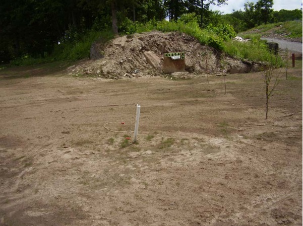
Figure 14-9 shows a white plastic casing extending out of the ground. The casing was originally placed plumb into the hole. The casing has been moved either by human activities or by the frost in the ground. The movement of the casing has affected the integrity of the annular seal around the casing. Surface water, contaminants and other foreign materials can migrate along the outside of the well casing into the monitoring well.
Figure 14-10: No Well Cap on Test Hole
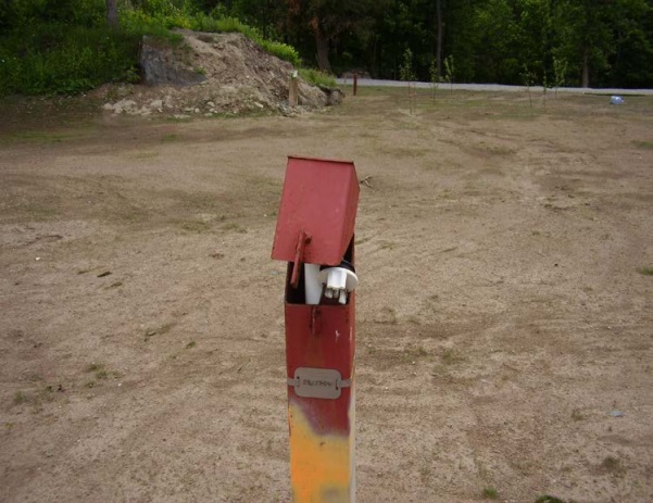
Figure 14-10 shows a protective cover held open by the well plug. The well plug is not on the top of the test hole. The opening at the top of the well casing can allow foreign materials to directly access the well. A well tag has been affixed to the protective cover upside down.
Figure 14-11: Test Hole With Unlocked Protective Cover
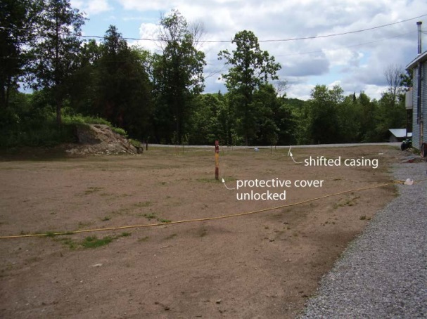
Figure 14-11 shows a red protective cover surrounding a test hole. A closer view of the protective casing is shown in Figure 14-10. The test hole shown in Figure 14-9 is located in the background of Figure 14-11 and to the right of the protective casing. The photograph shows how much the white plastic casing has been moved compared to its original plumb position.
Figure 14-12: Improper Casing Joint in Test Hole
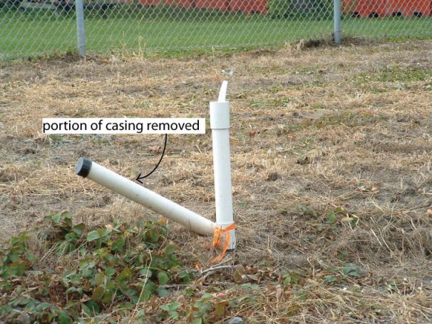
Figure 14-12 shows a test hole with white plastic casing. Instead of removing the well cap, a person has removed the upper portion of the casing and the cap from the upper coupling (joint) leaving the top of the well uncovered. As such, the casing joint is not watertight. Surface water and other foreign materials can access the well through the unsealed joint. Pumping equipment is also installed in the well. However, a well vent has not been installed on the well cap to exhaust any gases and allow the well to breathe in a proper manner.
Figure 14-13: Test Hole Casing Flush With Ground
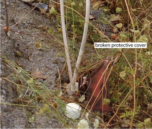
Figure 14-13 shows the white plastic well casing of a test hole in a protective cover. The well cap has been removed and placed in front of the well. The top of the protective cover has been broken off and is to the right of the well. The tube used for sampling is shown coming out of the well and looping back into the well. The ground surface slopes from the left to the right. Surface water, contaminants and other foreign materials can collect within the protective cover and enter the well. The well cap is not watertight. As such, surface water, contaminants and other foreign materials can migrate into the well.
Figure 14-14: Test Hole Casing Below Ground Surface
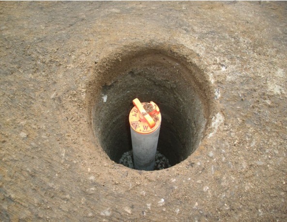
Figure 14-14 shows a well casing sealed with a locking well (or J) plug. The casing is completed below the ground surface. The annular space has been partially filled with dry bentonite to a distance below the top of the well casing. Surface water, contaminants and other foreign materials can collect within the annular space and enter the well. If the well plug is not watertight, surface water, contaminants and other foreign materials can migrate through the well cap, into the well.
Figure 14-15: Nested Multi-Level Test Hole With Seals
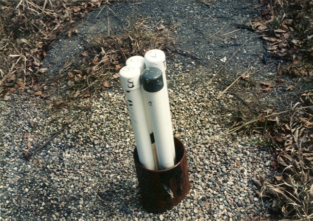
Figure 14-15 shows four casings of a nested multi-level test hole extending out of a permanent outer casing. Surface water, contaminants and other foreign materials can collect within the annular space between the plastic casings and the permanent outer casing. If the annular space is not properly sealed, surface water, contaminants and other foreign materials can migrate into the well.
Figure 14-16: Nested Multi-Level Test Hole With Seals And Flowing Well Conditions
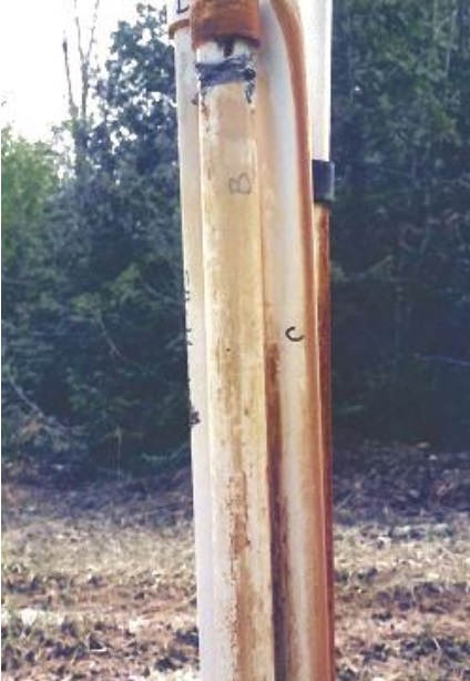
Figure 14-16 shows four casings of a nested multi-level test hole extending out of the ground. This test hole is located near a waste disposal site. Even though it is difficult to see in the photograph, groundwater is flowing from under the iron stained well cap at the top of the casing labeled “B”. The cap was originally sealed to casing “B” using duct tape (shown below the well cap). The force of the groundwater has pushed the cap up and away from the duct tape. Groundwater impacted by leachate is also leaking at the black joint of the casing located on the right side of the photograph. The flowing groundwater has caused iron staining on the casing below the joint. Also, groundwater impacted by leachate has leaked through cracks in casing “C.” The cracks were created by the pressure of the groundwater. The leachate may cause an adverse effect on the natural environment.
Figure 14-17: Test Hole With a Cracked Well Cap
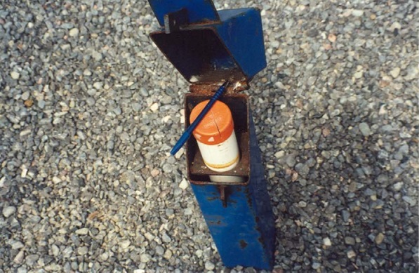
Figure 14-17 shows the protective cover opened to expose the orange cap on a test hole casing. The cap has been cracked. The opening in the cap can allow foreign materials to directly access the well. This test hole is located within two metres of a communal well that supplies water to more than 8,500 people.
Figure 14-18: Improper Well Caps on Test Holes
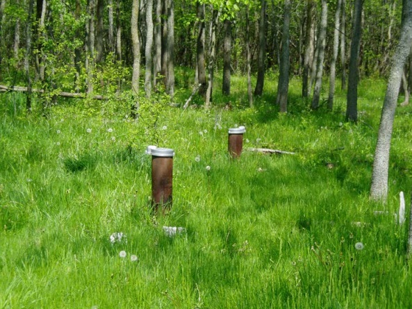
Figure 14-18 shows silver well caps on the casings of two test holes. Both caps are older style caps that are not considered vermin-proof. The caps have open accesses for the installation of electrical conduits (see the left side of the cap on the well in the foreground). Both well caps provide an access for foreign materials to enter the well.
Figure 14-19: Improper Hole Drilled in Well Cap
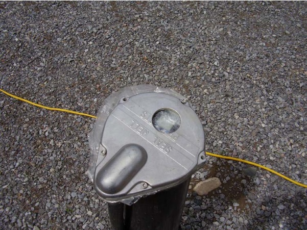
Figure 14-19 shows a hole drilled through a vermin-proof well cap on a dewatering well. A person has installed a thin piece of plastic between the two pieces of the cap in an attempt to seal the hole. As demonstrated in Figure 14-2 and Figure 14-3, foreign materials can break through the plastic, and enter the well.
Figure 14-20: Test Hole With an Unlocked Well Cap
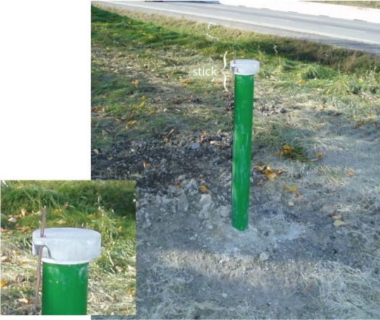
Figure 14-20 shows a lockable silver coloured well cap on top of a test hole’s green casing. A wooden stick is being used to hold the cap in place (see left side of cap) instead of a proper lock. Leaving the well cap unlocked allows for potential tampering with the well and does not provide quality assurance for water quality sampling.
Figure 14-21: Test Hole in a Creek
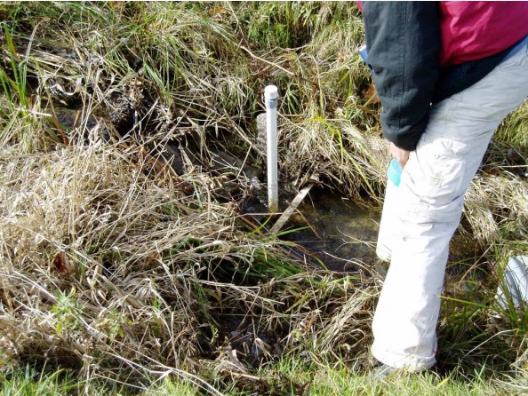
Figure 14-21 shows a test hole in a creek. Wells cannot be constructed in areas where the surface drainage is such that surface water will collect or pond in the vicinity of the well. Surface water and other foreign materials can potentially migrate down the outside of the casing.
Figure 14-22: Test Hole With Improper Well Cap, Casing and Surface Water Ponding
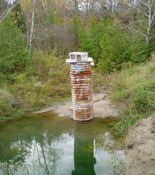
Figure 14-22 shows ponded water, which potentially contains pathogens located immediately beside the test hole. Ponded water can migrate downward through soil pores and along the side of the well casing. The well consists of galvanized casing that does not have watertight seams. The top of the well casing is covered by a wooden plank and concrete block. The well cover is not watertight. The cover and casing can allow surface water, contaminants and other foreign materials to enter the well.
The Maintenance Program
The maintenance program
- suggested frequency of physical inspections, maintenance and sampling based on the needs of the site,
- all available information about site-specific factors, benchmarks, geologic conditions and groundwater conditions (including geochemistry),
- an assessment of identified and potential problems,
- procedures for how these potential problems will be monitored and evaluated, and
- a decision making process on how to proceed to address problems as they occur.
Best Management Practice – “Cradle to Grave” Approach for Test Holes and Dewatering Wells
Test holes or dewatering wells are commonly found on sites where there are problematic and sometimes hazardous environmental conditions. The Ministry of the Environment and Climate Change frequently encounters sites where the person constructing the well, project manager and owner of the land have failed to meet their responsibilities and the well degrades and become pathways for contaminants. Therefore, it is important for a person involved in well design or construction to take a “cradle to grave” approach with every well installed for an environmental investigation, groundwater research project, remediation project or dewatering project. This means that, in addition to considering the existing conditions and the goals and objectives of the project that will affect how a well is designed and constructed, a clear plan should be in place to:
- address the ongoing requirements for well maintenance and, ultimately, proper abandonment of every well involved in a particular project to meet the Wells Regulation and minimize the risk of any well becoming a pathway for contamination,
- identify triggers regarding when a well would need to be repaired or properly abandoned, and
- identify the person or persons responsible for the implementation of the construction, maintenance and abandonment portions of the plan.
The “cradle to grave” plan should be retained at the site or with the persons responsible for the site and made available to all persons that may be involved in the construction, maintenance and abandonment of any test hole or dewatering well that is part of the project.
As part of the “cradle to grave” approach, a person constructing a test hole or dewatering well and any professional engineer or professional geoscientist managing these projects should take steps to ensure the owner of the land fully understands and agrees with:
- the cradle to grave approach for every well on the property, and
- the well owner’s ongoing legal obligations under the Wells Regulation to properly maintain or abandon every well on the property.
Note that, the well purchaser is one of the well owners with responsibilities for well maintenance and abandonment.
Proper maintenance of the test hole or dewatering well requires ongoing observation of the state of the well, along with the pumping and other equipment associated with the well and the surrounding area.
Best Management Practice– Regular Maintenance for Test Holes or Dewatering Wells
A test hole or dewatering well can often be left idle for long periods of time. Regular inspection, assessment and testing of the well are recommended to avoid impairment of the groundwater, safety hazards, clogging of the well screen or water intake, turbidity and corrosion. Quantities of sediment in samples should be recorded and compared through the life of the well.
A well maintenance checklist and some solutions are found in Table 14-1.
Download Table 14-1: Well Maintenance Checklist
Reminder: Where existing flush-mounted well pits (vaults) or other well pits are in use, they should be regularly inspected and must be properly maintained just like a well. Well pits are prone to collect contaminants, surface water or other foreign materials. Any contaminants, surface water or other foreign materials that collect in a well pit can potentially access the test hole or dewatering well through the top of the casing. This can be especially problematic on a contaminated site. If surface water or contaminants are entering a well pit, the well including the well pit must either be properly plugged and sealed or upgraded to prevent the surface water and contaminants from entering the well pit.
Reminder: Well owners or their consultant(s) should review the safety considerations found in this chapter and any safety plan associated with the site when conducting assessments or inspections of their test holes or dewatering wells.
Assessing the Interior of the Well with Video Technology Equipment
The lack of light and significant depth in many drilled and bored wells may result in unknown problems with the well’s structure, pumping equipment, water quantity or water quality because they are hidden from view. To assist in the visual inspection of the well, video cameras and other equipment can be installed into the interior of a well and linked to video terminals at the surface.
Down-hole video equipment can help assess:
- the well’s interior structure including the casing, casing joints and well screen,
- the pump and associated pumping equipment,
- water levels, water producing zones and depth,
- turbidity, colour and sediment problems, and
- biofilm and mineral encrustation problems.
Best Management Practice – Use Down-hole Video Equipment in Assessment of Well Problem
As part of a well assessment for a well problem, well owners or their consultants should consider retaining the services of businesses that have down-hole video equipment and who employ persons who have proper experience in installing the equipment and interpreting the video. In some cases, pumping equipment needs to be installed in the well with the video camera to lower the well’s water level to inspect the well.
The video should be recorded by the person conducting the inspection and the video should kept by the well owner for future reference and repairs.
Persons and businesses conducting this work should review Chapter 3: Exemptions: Wells, Activities & Experienced Professionals, and Chapter 4: Well Contractors & Well Technicians – Licences, Responsibilities & Exemptions to determine if they are required to be licensed for this activity.
Well Repair Requirements for Persons Constructing Wells
Requirements for Repairs and Alterations on Existing Test Holes and Dewatering Wells
Unless exempt, if a person performs a repair on an existing well and during the course of the repair, the person performs any type of well construction activity, then the person must:
- meet the requirements for existing wells found in the Wells Regulation, and
- hold a valid well technician licence of the correct class and hold, or work for someone that holds, a valid well contractor licence.
Definition - “Construct” when used with respect to a well, means bore, dig, drill or otherwise make, extend or alter. “Construct” also includes installing equipment in or connected to a well (see Table 2-1 in Chapter 2: Definitions & Clarifications).
Requirements for the construction of new test holes and dewatering wells are found in sections 12(well pits), 13 (casing), 14, 14.1 to 14.5 (annular space), and 14.11 (tags) of the Wells Regulation. Except for well tagging (see Chapter 15: Well Records, Documentation, Reporting & Tagging), these requirements will typically not apply to persons repairing or altering existing wells. For example, new well construction requirements do not apply when a person constructing a well:
- conducts a minor alteration on an existing well (see “Minor Alteration” in Table 2-1 in Chapter 2: Definitions & Clarifications and “Routine Repair” in Table 2-3 in Chapter 2: Definitions & Clarifications),
- replaces a pump or associated pumping equipment such as a pitless adapter or pitless unit into an existing well,
- extends a well casing above the ground surface,
- installs a new length of casing (commonly called a casing sleeve or liner) inside the well and
- removes a portion or section of well casing from the well.
Reminder: A well is considered to be a “new well” at the time when the initial hole (test hole or dewatering well) is constructed. See the definition of “new well” in Chapter 2: Definitions & Clarifications, Table 2-3.
Reminder: Equipment used in the redevelopment of an existing well, such as hydrofracturing, and other equipment installed in an existing well for rehabilitation purposes is not considered to be a routine repair. As such, this activity is an “alteration” to a well that is not a “minor alteration”.
Reminder: If an existing test hole or dewatering well is being altered (other than a minor alteration or pump and equipment installation) some regulatory requirements do apply. For example, the person constructing the well must complete a well record for the alteration (see Chapter 15: Well Records, Documentation, Reporting & Tagging).
Reminder: If an existing test hole or dewatering well without a well tag is being altered (other than a minor alteration) some tagging requirements apply (see Chapter 15: Well Records, Documentation, Reporting & Tagging). If an existing test hole or dewatering well with a broken, defaced, illegible, or otherwise unusable well tag is being altered (including a minor alteration) some tagging requirements apply (see Chapter 15: Well Records, Documentation, Reporting & Tagging).
Reminder: If an assessment determines that a repair or upgrade (alteration) of the well is required, it is recommended that the well owner retain a licensed well technician. The well technician that is retained must hold the correct class of licence and work for a licensed well contractor to conduct the recommended repair or upgrade of the well.
Some registered professionals (e.g., P. Eng, P. Geo, C.E.T.) working for licensed well contractors are exempt from the well technician licensing requirements for certain specified well construction activities (see Chapter 4: Well Contractors & Well Technicians – Licenses, Responsibilities & Exemptions).
Although the Ontario Water Resources Act allows a residential well owner to repair or upgrade (alter) his/her own well without a licence, if remuneration takes place (i.e., any form of compensation), or if the land owner is a business corporation, partnership, sole proprietor or a government agency, the land owner must retain a licensed well contractor and employ licensed well technicians of the correct class to alter or repair the well.
Reminder: To determine which prescribed well technician licence class applies to the type of work being performed on an existing well see Chapter 4: Well Contractors & Well Technicians – Licences, Responsibilities & Exemptions.
Alterations Not Considered Minor Alterations
Unless exempt, the person performing an alteration to a test hole or dewatering well must meet, as a minimum, maintaining field notes (section 12.1), covering the well (section 12.2), surface drainage (section 12.3), flowing well (section 14.7), well yield (sections 14.9 and 14.10), well tagging (section 14.11), venting (section 15.1), equipment connections (section 15.2), caps and covers (section 15.2), clean equipment (section 15.3), natural gas (section 16), well record (section 16.3) and casing height maintenance [subsection 20(2)] requirements found in the Wells Regulation.
Minor Alterations
There are some requirements in the Wells Regulation that will apply also to a “minor alteration”. Unless exempt, the person performing a minor alteration to a test hole or dewatering well must meet, as a minimum, covering the well (section 12.2), surface drainage (section 12.3), flowing well (section 14.7), well tagging and well record completion for broken or defaced well tags (section 14.11), venting (section 15.1), equipment connections (section 15.2), caps and covers (section 15.2), clean equipment (section 15.3), natural gas reporting (section 16), and casing height maintenance [subsection 20(2)] requirements found in the Wells Regulation.
Casing Height When Performing Work on or Near a Test Hole or Dewatering Well
The Wells Regulation - Persons, including well owners, should be aware of the following Wells Regulation requirements when performing any routine well maintenance, repair or alteration or when performing other work, such as landscaping or construction, around a well:
- Where a casing height extends greater than or equal to 40 cm (16 inches) above the ground surface, the top of the casing must not be reduced to a height of less than 40 cm (16 inches) above the ground surface.
- Where the well is an existing well and the casing height extends less than 40 cm (16 inches) above the ground surface, the top of the casing must not be reduced to a height of less than the original casing height.
If a test hole or dewatering well is located in an area where vehicle traffic or pedestrians are likely to pass directly over the well, the requirement to maintain the casing height as stated above does not apply to the test hole or dewatering well when it is completed with a flush-mounted watertight commercially manufactured well cover. If used, all the Wells Regulation requirements for the use of this type of cover must be met (see Chapter 9: Completing the Test Hole or Dewatering Well Structure and Chapter 12: Equipment Installation for further information).
An exemption to the minimum casing height requirement above the ground surface also exists if the test hole or dewatering well is made by the use of a jetted point or driven point and meets the requirements listed in the “Exemption - Maintaining Casing Height for Driven Point or Jetted Point New Wells” portion of the “Plainly Stated” section of this Chapter.
Installing Used Equipment During Well Repair or Maintenance
The Wells Regulation allows for the installation of used pumps, pumping equipment, vents, covers, caps, casing, well screens, pitless adapters, pitless units and other equipment in existing test holes and dewatering wells.
The Wells Regulation - All new or used equipment installed in or connected to a well must be clean and must not impair the quality of the groundwater or aquifer. Well owners must maintain all installed equipment to ensure it does not impair the quality of the groundwater.
Best Management Practice – Ensuring Equipment is New and Chlorinated
In addition to the requirement that equipment be clean and free of contamination, anyone working on an existing test hole or dewatering well should:
- install new parts, devices and materials,
- install parts, devices and materials that are suitable for the particular type of environment and well,
- clean and sanitize the parts, devices, materials and well construction equipment with chlorinated water as recommended in the “Sanitary Practices” section in Chapter 10: Test Hole & Dewatering Well Exemption & Recommended Activity: Disinfection, and
- always ensure parts, devices and materials are installed to the manufacturer’s specifications.
Reminder: The above best management practice regarding the use of chlorinated water should not be applied if the contamination in the groundwater being investigated is expected to react with the chlorine solution on the equipment unless the equipment is thoroughly rinsed prior to installation.
Safeguarding & Protecting the Well Tag
The Wells Regulation - It is not permitted to deface, alter, conceal or obstruct a well tag.
The Wells Regulation - It is not permitted to remove a well tag that is affixed to a well unless the:
- person has the written consent from the Director;
- well tag on the well that is being altered is broken, defaced, illegible or otherwise unusable; or
- well is being altered or abandoned (plugged and sealed).
The Wells Regulation - It is not permitted to use a well tag issued by the Ministry except in accordance with the Wells Regulation.
The Wells Regulation - During alterations to a cased well with a well tag, the well tag must be safeguarded and, if removed, it must be re-affixed permanently to the outside of the casing or to a permanent structure associated with the well, upon completion of the alteration.
Reminder: Any damaged well tags must be returned to the Ministry and be replaced (see Chapter 15: Well Records, Documentation, Reporting & Tagging for further information).
Rehabilitation of an Existing Test Hole or Dewatering Well
There are several indicators that a test hole or dewatering well may require rehabilitation. For example:
- observed reduction in the yield of a dewatering well used to lower the water table or as part of a pump and treat system to collect contaminated groundwater,
- unexpected or unanticipated changes observed in groundwater characteristics (e.g., water quality field and laboratory analyses results, colour, odour) during or after purging the test hole, and
- observed structural damage (e.g., missing casing and cap above the ground surface).
These and other indicators or triggers for rehabilitation should be captured as part of the maintenance program for the site. A properly administered maintenance program will ensure that problems are identified and addressed in a timely fashion.
Best Management Practices – Retaining Professionals to Assess and Rehabilitate Test Holes and Dewatering Wells
As each well and each environment is different, a Professional Engineer or a Professional Geoscientist should assess any problem test hole or dewatering well and the groundwater to identify the source of the issue and provide recommendations on a case by case basis. In some cases, a licensed well technician with the correct class of licence working for a licensed well contractor can conduct the assessment of the well. If the assessment concludes that rehabilitation of the well is required, it is important to determine which prescribed well technician licence class applies to the types of work being performed on an existing well (see Chapter 3: Exemptions: Wells, Activities & Experienced Professionals and Chapter 4: Well Contractors & Well Technicians – Licences, Responsibilities & Exemptions).
Reminder: In certain circumstances it may be advisable to chlorinate the well after rehabilitation activities (see Chapter 10: Test Hole & Dewatering Well Exemption & Recommended Activity: Disinfection).
Best Management Practice – Consulting Well Rehabilitation Literature
The following literature provides information on the rehabilitation of wells including biofilm and mineralization problems and should be reviewed:
- Water Well Rehabilitation, A Practical Guide to Understanding Well Problems and Solutions
footnote 4 , - Chemical Cleaning, Disinfection and Decontamination of Water Wells
footnote 5 , - ASTM D5978-96 (2005) – “Standard Guide for Maintenance and Rehabilitation of Ground-Water Monitoring Wells”
footnote 6 , - Groundwater and Wells: Third Edition
footnote 7 , Chapter 13: pg 597 to 628, - Practical Handbook for Environmental Site Characterization and Groundwater Monitoring
footnote 8 - In particular Chapter 12: Monitoring Well Post-Installation Considerations, pg 868 to 872, and - Construction, Dewatering and Groundwater Control
footnote 9 – pages 195 to 221.
Safety Considerations When Maintaining and Rehabilitating Wells
There are many serious dangers associated with test holes and dewatering wells that must be considered when maintaining and rehabilitating wells. Important precautionary actions to take include:
- making sure that the power supply to the pump has been shut off to minimize the risk of shock or electrocution when inspecting a well,
- safeguarding the well site any time the well cap or cover is removed to minimize hazards, and
- following all applicable safety plans for the site.
Reminder: A person must not enter any confined space (e.g., non-ventilated areas including well pits, pump houses, and others defined in the O. Reg. 632/05 under the Occupational Health and Safety Act), unless properly trained and equipped. Confined spaces present asphyxiation hazards and some wells produce naturally occurring gases that may be poisonous and/or explosive.
Reminder: For further information on safety plans see the “Safety Considerations When Working on Contaminated Sites,” section in Chapter 6: Constructing the Hole, Casing & Covering the Test Hole or Dewatering Well.
When maintaining wells, well owners should be made aware of the many serious risks associated with wells including explosive gases and electrocution. Since most well owners are not familiar with these potential hazards, licensed well technicians, knowledgeable with respect to these hazards, and working for licensed well contractors should always be hired to work on the well. Some registered professionals (e.g., P. Eng, P. Geo, C.E.T.) working for licensed well contractors are exempt from the well technician licensing requirements for certain specified well construction activities (see Chapter 3: Exemptions: Wells, Activities & Experienced Professionals and Chapter 4: Well Contractors & Well Technicians – Licenses, Responsibilities & Exemptions). Any professionals working on test holes or dewatering wells should be knowledgeable about health and safety hazards.
It is important that anyone working on a test hole or dewatering well:
-
obtain and follow the guidelines set out in the Material Safety Data Sheet (MSDS) for any chemical product used in the rehabilitation. The MSDS will include the following:
- properties of the material,
- hazards associated with the material,
- personal protective equipment (PPE) required when using the material,
- contact information, and
- first aid and medical attention information.
- make sure that all rehabilitation products are approved for the intended use and will not impair the quality of the groundwater.
- check product labels to verify product contents, proper use and storage
Reminder: Safety practices and requirements (e.g., Workplace Hazardous Materials Information System training), as regulated and advocated by the Ministry of Labour, must be followed.
Footnotes
- footnote[1] Back to paragraph ASTM D5978-96 (2005) – Standard Guide for Maintenance and Rehabilitation of Ground-Water Monitoring Wells. (DOI: 10.1520/D5978-96R05) West Conshohocken, PA. ASTM International Website. Section 7.1 Maintenance Planning, Monitoring and Treatment, P4.
- footnote[2] Back to paragraph ASTM 5978-96 (2005) – “Standard Guide for Maintenance and Rehabilitation of Groundwater Monitoring Wells,” DOI: 10.1520/D5978-96R05. ASTM International, West Conshohocken, PA. ASTM International Website. (Section 7 – “Maintenance Planning, Monitoring and Treatment,” p4).
- footnote[3] Back to paragraph ASTM 5978-96 (2005) – “Standard Guide for Maintenance and Rehabilitation of Groundwater Monitoring Wells,” DOI: 10.1520/D5978-96R05. ASTM International, West Conshohocken, PA. ASTM International Website. (Section 7.3 Maintenance Program Design, p4).
- footnote[4] Back to paragraph Mansuy, Neil. 1999. Water Well Rehabilitation, A Practical Guide to Understanding Well Problems and Solutions. CRC Press LLC. Boca Raton, FL.
- footnote[5] Back to paragraph Schnieders, John H. 2003. Chemical Cleaning, Disinfection & Decontamination of Water Wells. Johnson Screens Inc. St. Paul, MN.
- footnote[6] Back to paragraph ASTM D5978-96 (2005) – “Standard Guide for Maintenance and Rehabilitation of Ground-Water Monitoring Wells” 10.1520/D5978-96R05. ASTM International, West Conshohocken, PA. ASTM International Website.
- footnote[7] Back to paragraph Sterrett, Robert J. 2007. Groundwater & Wells: Third Edition. Johnson Screens/A Weatherford Company. New Brighton, MN.
- footnote[8] Back to paragraph Nielsen, David M. 2006. Environmental Site Characterization and Ground-Water Monitoring: Second Edition. CRC/Taylor & Francis Group. Boca Raton, FL.
- footnote[9] Back to paragraph Powers, J. Patrick. Et al. 2007. Construction Dewatering and Groundwater Control: New Methods and Applications: Third Edition. John Wiley & Sons, Inc. Hoboken, NJ.