12. Equipment Installation
Chapter Description
This chapter provides information, illustrations, advantages and disadvantages of various pump types and groundwater monitoring equipment. This chapter covers the requirements and exemptions for the installation of equipment in test holes and dewatering wells and provides information on the installation of equipment in wells completed above ground and in well pits. The requirements listed in this chapter do not apply to shallow works or other exempted wells discussed in Chapter 3: Exemptions: Wells, Activities & Experienced Professionals.
Regulatory Requirements – Equipment Installation
Relevant Sections – The Wells Regulation
Exemptions – Section 1.0.2
Installation of Equipment – Sections 15.2 to 15.3
Venting – Section 15.1
Surface Drainage – Section 12.3
Flush Mount Covers – Subsection 13(11)
Well Pits – Subsection 12(7.1) and 12(9) paragraphs 1, 2 and 3, subsection 13(14) and Section/Subsection 14.5, 14.5(3)
The Requirements – Plainly Stated – Installing the Equipment
The Wells Regulation Provides Exemptions for the Following Activities Related to Equipment Installation
Exemptions for Equipment and Activities
Well licensing requirements in the Ontario Water Resources Act and the requirements in the Wells Regulation do not apply to any of the following activities that are part of the construction of a well:
- Inspecting the well using equipment that is not left unattended in the well.
- Monitoring, sampling or testing the well using equipment that:
- is not used to test the yield of the well or the aquifer, and is not left unattended in the well, or
- is not used to test the yield of the well or the aquifer, and was previously installed in the well.
- Installing equipment for monitoring, sampling or testing a test hole or dewatering well, unless the:
- installation of the equipment involves an alteration of the well, other than notching the top of the casing, or
- equipment is used to test the yield of the well or the aquifer
Reminder: See Chapter 3: Exemptions: Wells, Activities & Experienced Professionals for further information on how to apply the exemptions for installing and using equipment in wells.
Reminder: See Chapter 4: Well Contractors & Well Technicians – Licences, Responsibilities & Exemptions for information on licensing for equipment installation activities that are not exempt from the well licensing requirements in the Ontario Water Resources Act and the requirements in the Wells Regulation.
The Wells Regulation Requires a Person Constructing a Test Hole or Dewatering Well to Meet the Following, Unless an Exemption is Provided in This Section or in Chapter 3: Exemptions: Wells, Activities & Experienced Professionals
Equipment in a Test Hole or Dewatering Well
Any equipment installed in a test hole or dewatering well must be clean.
Shallow works and the activities listed in the "Exemptions for Equipment and Activities" section are exempt from the Wells Regulation requirements.
Reminder: All equipment installed in a test hole or dewatering well must not cause or have the potential to cause impairment to the water in the well or the groundwater as required under Subsection 30(1) of the Ontario Water Resources Act.
Reminder: See Chapter 3: Exemptions: Wells, Activities & Experienced Professionals for information on shallow works and other exempted wells.
Connections to Drilled Wells
If a connection to the casing of a drilled well is made below the ground surface, a well seal or pitless adapter must be used and the connection must be made watertight.
Pitless units, which consist of a pitless adapter and casing, are also an acceptable method to connect pumping equipment to drilled wells.
A cutting torch must not be used to make an opening in the casing wall when installing a pitless adapter.
Connections to Wells Other Than Drilled Wells
Any below ground connection to the casing of a well that is not a drilled well must be made watertight with durable bonding material.
Excavation beside the Casing
Any excavation created when making a below ground connection to the casing of a well must be filled with suitable sealant extending from the casing a minimum distance outward of 20 cm (8 inches) and extending from the bottom of the excavation to within 20 cm (8 inches) of the ground surface.
Venting – General
When a new dewatering well is constructed, the well must be vented to the outside atmosphere in a manner that will safely disperse all gases.
Exemptions - General Venting Requirement
The above venting requirement does not apply to a:
- test hole, or
- dewatering well where the casing will be used to transmit water out of the well (e.g., driven point dewatering system).
Venting –Drilled Well with a Pump
If a pump is installed in a drilled well the following air vent requirements apply:
- An air vent must be installed with a minimum inside diameter of:
- 0.3 cm (0.11 inches), if the inside diameter of the casing is less than 12.7 cm (5 inches), or
- 1.2 cm (0.48 inches), if the inside diameter of the casing is 12.7 cm (5 inches) or more,
- The air vent must:
- be long enough to extend above the covering of the well pit, if a well pit exists, or
- extend above the ground surface at least 40 cm (16 inches) and at a height sufficient to prevent the entry of flood water from any anticipated flooding in the area, if no well pit exists, and
- The open end of the air vent must be shielded and screened to prevent the entry of any materials into the well.
Exemptions - Venting - Drilled Well with a Pump
The venting requirements for a drilled well installed with a pump do not apply to:
- an uncased test hole or dewatering well,
- a test hole or dewatering well with a well pit where there is no potential hazard from natural gas or any other gas, or
- a test hole or dewatering within a flush-mounted well pit (vault) including a watertight commercially manufactured well cover where there is no potential hazard from natural gas or any other gas.
Venting a Well in a Well Pit
Except for a flush-mounted well pit (vault), an air vent line must be installed on a new drilled test hole or dewatering well in a new well pit and must extend above the cover of the well pit. The specific size and other requirements discussed in Venting – Drilled Well with a Pump in this Plainly Stated section do not apply.
Exemption - Venting a Well in a Flush-Mounted Well Pit (Vault)
An air vent line is not required to be installed on a test hole or dewatering well within a new flush-mounted well pit (vault).
Covering the Well
Dug or Bored
The top of the casing of a well that is constructed by digging or boring must be covered with a solid, watertight well cover, sufficient to prevent surface water and other foreign materials from entering into the well.
Drilled or Other Method
The top of the casing of a well that is constructed by any method other than digging or boring, such as drilling, must be sealed with a commercially manufactured vermin-proof well cap. This includes a properly installed and sealed sanitary well seal and a watertight and airtight well cap for a driven or jetted point well.
Reminder: In certain circumstances, a well can be completed with a flush-mounted watertight commercially manufactured well cover sufficient to prevent the entry of surface water and other foreign materials into the well. Depending on the type of well, the flush-mounted cover must also meet the well cover or well cap requirements stated above if it is used to cover or seal the top of the well casing. See the "Flush-Mounted Well Cover" section in the "Plainly Stated" for further requirements.
Alternative to a Well Cover
The cover or seal previously mentioned in the "Covering the Well" in the Plainly Stated section (above) is not required if all of the following criteria are met:
- A floor has been constructed around or adjacent to the casing of the well,
- A pump is installed above or adjacent to the well,
- The top of the casing is shielded to prevent entry of any material that may impair the quality of the water in the well, and
- The casing of the well extends at least 15 cm (6 inches) above the floor.
Reminder: The installation of a well cap or watertight well cover is considered a "minor alteration" to a well.
Flush-Mounted Well Cover
Where the test hole or dewatering well is located in an area where vehicle or pedestrian traffic is likely to pass directly over the well, the test hole or dewatering well can be completed with a flush-mounted watertight commercially manufactured well cover that is:
- sufficient to prevent entry of surface water and other foreign materials into the well, and
- sufficiently strong, durable and properly installed to protect the well from damage, or the cover must be covered with a metal plate that is sufficiently large and sufficiently strong, durable and properly installed to protect the well cover and the well from damage.
Well Pits
In most circumstances, well pits are not allowed to be constructed on new or existing test holes or dewatering wells.
In certain circumstances, however, a person constructing a new test hole or dewatering well may be allowed to finish the well with a well pit. The Wells Regulation provides options for the construction of permitted well pits depending on the location of the well, the type of equipment used to construct the well and the well’s purpose.
The sections below provide the Wells Regulation construction requirements for various well pit scenarios.
Flush-Mounted Well Pit (Vault)
In Ontario, there are commercially manufactured well pit assemblies for test holes and dewatering wells. The industry commonly calls these well pits flush-to-grade well vaults, well vaults or flush-mounted well pits. This type of assembly is considered a well pit with a flush-mounted watertight commercially manufactured well cover.
To assist the industry, this manual describes a well vault as a "flush-mounted well pit (vault)". Further clarification is provided in the Glossary and in Table 2-3 of Chapter 2: Definitions & Clarifications under the terms "well pit" and "flush-mounted watertight commercially manufactured well cover".
The requirements in the following sections must be met for new flush-mounted well pits (vaults). Further information on flush-mounted well pits (vaults) is provided in Chapter 9: Completing the Test Hole or Dewatering Well Structure and Chapter 14: Test Hole & Dewatering Well Maintenance & Repair, "Plainly Stated" section.
Location
A test hole or dewatering well is only allowed to be constructed in a flush-mounted well pit (vault) if the well is located where vehicle or pedestrian traffic is likely to pass directly over the well.
Flush-Mounted Well Pit Walls (or Casing)
The walls of the flush-mounted well pit (vault) are considered casing.
The casing requirements found in Chapter 6: Constructing the Hole, Casing & Covering the Test Hole or Dewatering Well and Chapter 9: Completing the Test Hole or Dewatering Well Structure in this manual must apply to the sides of a well pit (i.e., casing) when a new well pit is constructed.
Surface drainage must not collect or pond in the vicinity of the well pit’s casing.
Flush-Mounted Well Pit (Vault) Floor
The floor of the well pit must be covered with at least 10 cm (4 inches) of suitable sealant that, when set to a solid state, will be capable of supporting the weight of a person.
Flush-Mounted Well Pit (Vault) Cover
The top of the new flush-mounted well pit (vault) must be covered with a solid, watertight cover. The flush-mounted cover must also meet the requirements in the "Flush-Mounted Well Cover" section in the "Plainly Stated".
Reminder: The well casing located inside the new flush-mounted well pit (vault) must be sealed with a commercially manufactured vermin-proof well cap (see previous section "Covering the Well").
Reminder: For additional requirements that apply to new flush-mounted well pits (vaults), see the "Creating and Filling the Annular Space for a New Flush-Mounted Well Pit (Vault) and Other Well Pits" and "Surface Drainage" sections below.
Reminder: Well pit requirements that are found in the "Other Permitted Well Pits" section below, but that are not listed in this section, do not apply to flush-mounted well pits (vaults).
Other Permitted Well Pits
A new well pit, other than a flush-mounted well pit (vault), is permitted for new test holes and dewatering wells as long as the well is constructed with diamond drilling equipment in connection with mineral exploration.
Reminder: Diamond drilling equipment can be described as any drilling equipment that uses a diamond bit. Further clarification on the term "mineral exploration" is provided in Table 2-3 of Chapter 2: Definitions & Clarifications.
The requirements in the following sections must be met in order to install a new well pit on a test hole or dewatering well constructed with diamond drilling equipment in connection with mineral exploration.
Well Pit Walls (or. Casing)
The walls of the new well pit are considered casing.
When a new well pit is constructed, the casing requirements found in Chapter 6: Constructing the Hole, Casing & Covering the Test Hole or Dewatering Well, and Chapter 9: Completing the Test Hole or Dewatering Well Structure of this manual apply to the sides of a well pit. This includes the top of the sides of the well pit (i.e., casing) being at least 40 cm (16 inches) above the highest point on the ground surface within 3 m (10ft) radially from the outside of the well pit’s casing.
Surface drainage must not collect or pond in the vicinity of the well pit’s casing.
Well Pit Floor
The floor of the new well pit must be covered with at least 10 cm (4 inches) of suitable sealant that, when set to a solid state, will be capable of supporting the weight of a person.
Cover/Seal and Vent for a Test Hole or Dewatering Well Located in a New Well Pit
The top of the casing of the test hole or dewatering well in the new well pit must be:
- at least 40 cm (16 inches) above the floor of the well pit, and
- sealed with a commercially manufactured sanitary seal. An air vent line must be provided from the seal to above the covering of the well pit.
Well Pit Cover
The top of the new well pit must be covered with a solid, watertight cover. The well pit cover must be:
- sufficiently sealed to prevent the entry of surface water and other foreign materials which would include insects and animals, and
- fastened in place in a manner that will make it difficult for children to remove the well pit cover.
Keeping the Well Pit Dry
The new well pit must be kept dry by means of a sump pump unless the water table is substantially lower than the floor of the well pit.
If the water table is substantially lower than the floor of the well pit, the new well pit may be kept dry by means of a drainage pipe from the well pit that:
- has a one-way valve to allow water to discharge from the pit but prevents surface water and other foreign materials, including insects and animals, from entering the well pit,
- passes through the layer of sealant, and
- allows water to discharge near the perimeter of the well pit.
Reminder: For additional requirements that apply to permitted well pits, see the "Creating and Filling the Annular Space for a New Flush-Mounted Well Pit (Vault) and Other Well Pits" and "Surface Drainage" sections below.
Creating and Filling the Annular Space for a New Flush-Mounted Well Pit (Vault) and Other Well Pits
The person constructing the well must ensure that the entire new well pit, from the bottom of the well pit to the ground surface, is constructed with a diameter that is at least 7.6 cm (3 inches) greater than the outside diameter of the well pit’s walls (or casing).
Unless otherwise exempt, the person constructing the well must ensure that any annular space outside the new well pit’s casing is filled, from the bottom of the well pit to the ground surface, with suitable sealant.
The sealant must provide the appropriate structural strength to support the weight of persons and vehicles that may move over the area after it is filled.
If the sealant contains cement:
- it must be allowed to set according to the manufacturer’s specifications or for 12 hours, whichever is longer; and
- if after setting, the sealant has settled or subsided, it must be topped up to the ground surface.
Exemption - Creating and Filling the New Well Pit’s Annular Space
The above requirements on how to create and fill an annular space for a well pit do not apply for a test hole or dewatering well that is scheduled to be abandoned within 180 days after completion of the well’s structure.
Surface Drainage
The mounding of the ground surface beside the well must be done so that the surface drainage does not pond or collect in the vicinity of the well. Additional information on surface drainage can be found in Chapter 9: Completing the Test Hole or Dewatering Well Structure.
Reminder: The regulatory exemptions regarding test holes and dewatering wells allow for well technicians, engineers and geoscientists to use their professional expertise to design and install test holes and dewatering wells on a case by case basis, thereby enabling the testing, sampling or dewatering of various groundwater intervals.
Requirements for the Records of Site Condition regulation are provided in the following sections of this chapter:
- Sampling and Monitoring Equipment
- Groundwater Sampling
- Groundwater Level and Other Monitoring Equipment
- Well Caps and Covers
- Creating and Filling the Well Pit’s Annular Space
Relevant Additional Regulations or Legislation
Ontario Regulation 153/04 as amended (Records of Site Condition) made under the Environmental Protection Act, R.S.O. 1990, Chapter E. 19
Ontario Regulation 164/99 as amended (Electrical Safety Code) made under the Electricity Act, 1998, S.O. 1998, Chapter 15, Schedule A
Ontario Regulation 632/05 as amended (Confined Spaces) made under the Occupational Health and Safety Act, R.S.O. 1990, Chapter O. 1
Ontario Regulation 213/91 as amended (Construction Projects) made under the Occupational Health and Safety Act, R.S.O. 1990, Chapter O. 1
Relevant Standards
ASTM D 5088-02 (Reapproved 2008) – "Standard Practice for Decontamination of Field Equipment Used at Waste Sites." (DOI: 10.1520/D5088-02R08)
ASTM D 5092-04e1 – "Standard Practice for Design and Installation of Ground Water Monitoring Wells." (DOI: 10.1520/D5092-04E01)
ASTM D 5608-01 (Reapproved 2006) – "Standard Practices for Decontamination of Field Equipment Used at Low Level Radioactive Waste Sites" (DOI: 10.1520/D"5608-01R06)
ASTM D 5787-95 (Reapproved 2009) – "Standard Practice for Monitoring Well Protection" (DOI: 10.1520/D5787-95R09)
ASTM D 5978-96 (Reapproved 2005) – "Standard Guide for Maintenance and Rehabilitation of Ground-Water Monitoring Wells" (DOI: 10.1520/D5978-96R05)
Relevant Guidelines
Guidance on Sampling and Analytical Methods for Use at Contaminated Sites in Ontario, Ontario Ministry of Environment and Energy, Standards Development Branch December, 1996.
Preferred Operating Practices for Borehole/Monitoring Well Installation and Associated Soil/Groundwater Sampling at Hydrocarbon Impacted Sites, Imperial Oil, May 15, 2002
Australian Drilling Industry Training Committee Limited, Drilling – The Manual of Methods, Applications and Management. CRC, Lewis Publishers, Boca Rata, New York, 1996
Monitoring Well Design, Installation and Documentation at Hazardous, Toxic, and Radioactive Waste Sites, Report A301204. US Army Corps of Engineers. 1998
The Safety Manual for Well Technicians. (Supplemental course material). Fleming College, School of Continuing Education and Skilled Trades. 2008
WSC Performance Standards and Recommended Installation Procedures for Sanitary Water Well Pitless Adapters, Pitless Units, and Well Caps, PAS-97(04), 2004
Key Concepts
What to Consider When Installing Equipment
It is important to consider the protection of health, safety and the environment when installing equipment. Unless exempt, the following requirements and considerations are relevant to the installation of equipment:
- Anything that is put into the well must not impair the quality of the water,
- The purpose for installing equipment (e.g., measuring),
- The sanitary well seal, cover or cap must be properly secured on the top of the test hole or dewatering well to prevent the entry of surface water and other foreign materials,
- Other than sample collection, contaminants should not enter or exit the well during any monitoring or sampling events,
- Any space around the waterline through the side of the casing or through the top of the casing must be made watertight, and
- In the case where a pump is installed in a dewatering well, for example, the final grade of the ground surface must allow for the proper height of casing and must not allow ponding of water in the vicinity of the well.
Reminder: Chapter 3: Exemptions: Wells, Activities & Experienced Professionals provides clarification when the requirements in bullets 2 to 6 do not apply.
Best Management Practice – Installing Equipment
Anyone constructing (including installing equipment in) a test hole or dewatering well should:
- install new and undamaged parts, devices and materials in the test hole or dewatering well that are certified to meet the National Sanitation Foundation (NSF) International standards,
- install parts, devices and materials that are suitable for the particular type of environment and test hole or dewatering well,
- if necessary, clean the equipment with chlorinated water as suggested by AWWA C654 standard titled "Disinfection of Wells or the Michigan’s Water Well Disinfection Manual", and
- ensure parts are installed to the manufacturers’ specifications.
Best Management Practice – Retain Licensed Persons to Perform Exempted Activities on Wells
To help further protect groundwater, exempted activities performed on test holes and dewatering wells should be done:
- by properly qualified persons (e.g., licensed well technician or qualified professional) and
- to meet the requirements found in the Wells Regulation and best management practices found in this manual.
Sampling and Monitoring Equipment
The purpose of groundwater sampling and monitoring programs is to obtain accurate samples and measurements that are representative of the groundwater or aquifer in a study area. Inconsistent and biased samples and measurements lead to incorrect interpretations and wrong remedial actions.
Depending on the purpose of the program or study, there are various types of equipment for field measurements (e.g., water level meters, flow-through cells, pH meters, conductivity meters, and temperature meters) and sampling (e.g., passive samplers, bailers, inertial lift pumps, bladder pumps, and submersible pumps).
Connections to Wells
Connections may be required for a test hole or dewatering well to function properly. Connections can be made above and below the ground surface to accommodate waterlines or instrumentation to enter a well, for instance. Any connection must be made watertight. This reduces the risk of contamination of both the well and the aquifer.
Venting the Well
The purpose of the vent is to allow the well to breathe, which allows equalizing pressures (i.e., when water is drawn out, air goes in so the column of water is at atmospheric pressure at all times), and allow the safe venting of natural gas and other gases to the outside atmosphere.
Well Caps & Covers
Proper covering of the test hole or dewatering well prevents the entry of foreign materials into the groundwater. Proper capping and covering will also help to assure that groundwater quality samples are not biased by surface water, contamination, or other foreign materials. Securing the test hole or dewatering well is a safeguard against unauthorized entry into the well, vandalism or tampering. Securing the well includes ensuring that the well cap, seal or cover is on properly and may include the use of a protective cover with locking cap, barriers or fences. For information on securing the well refer to Chapter 9: Completing the Test Hole or Dewatering Well Structure.
Casing Height & Mounding
The purpose of the minimum casing height is to prevent water from entering the well and to allow for venting. The purpose of mounding is to ensure that surface runoff does not pond in the vicinity of the well and infiltrate into the well. When installing or connecting equipment, the minimum casing height must be maintained and any mounding around the well that has been disturbed must be restored to meet the drainage requirements found in the "Plainly Stated" section of this chapter. This does not apply if the equipment installation is exempt from the Wells Regulation (e.g., measuring the water level in a well using a water level meter) or if the equipment is installed in an exempted well (see Chapter 3: Exemptions: Wells, Activities & Experienced Professionals for further information).
Well Pits
A well pit is an enclosed structure located at and below the ground surface that houses the top of the well and any associated pumping equipment. The top of the well casing extends out of the floor of the well pit.
A flush-mounted well pit (vault), used in test hole construction, is a type of well pit.
A well pit, other than a flush-mounted well pit, is usually installed at or near the time of pump and associated equipment installation in the well.
The well pit can:
- protect the well from outside environmental conditions such as freezing of waterlines and the entry of surface water runoff and other foreign materials, and
- allow access to the well and pumping system from the ground surface for maintenance and repair
Health and Safety Considerations: Trenches, Confined Spaces and Electrical
The safety manual from the well drilling continuing education course provides details regarding safety when excavating or working in trenches and confined spaces, along with precautions for working with or around electrical lines. This manual is available from Sir Sanford Fleming College (see the Resources section of this manual). It is recommended that these guidelines and the Occupational Health and Safety Act and its relevant regulations be reviewed prior to taking on any related tasks. Failure to be aware of the surroundings and to follow appropriate safety procedures could result in serious injury or death.
Sampling and Monitoring Equipment
The Wells Regulation requires a person constructing a test hole or dewatering well to meet the following, unless an exemption is provided in the Plainly Stated section of this chapter or in Chapter 3: Exemptions: Wells, Activities & Experienced Professionals.
Wells Regulation: Any equipment installed in a test hole or dewatering well must be clean as required by the Wells Regulation.
Reminder: All equipment installed in a test hole or dewatering well must not cause or have the potential to cause impairment to the water in the well or the groundwater as required under subsection 30(1) of the Ontario Water Resources Act.
Reminder: For further information on what activities or wells are exempt and what activities and wells require licensing, see Chapters 3: Exemptions: Wells, Activities & Experienced Professionals and Chapter 4: Well Contractors & Well Technicians – Licences, Responsibilities & Exemptions.
Records of Site Condition Regulation: Starting on July 1, 2011, amendments to O. Reg. 153/04 came into force and apply to phase two environmental site assessments (ESAs) conducted in support of records of site conditions (RSCs). For any such RSC submitted on or after this date where, for example, an existing developed monitoring well is used, the following requirements apply:
Requirements Related to Equipment Installation & Use
- The qualified person must ensure that there is a sampling and analysis plan that includes a quality assurance and quality control (QA/QC) program. The QA/QC program must include a requirement that all non-dedicated sampling and monitoring equipment be cleaned following each use.
- Where sampling of groundwater is being undertaken to demonstrate if the applicable site condition standard for a contaminant has been met or not, the qualified person must ensure that:
- A monitoring well from which a sample is to be collected has been appropriately purged immediately prior to sampling
- The well purging referred to above is documented by recording:
- the date of the purging,
- the time the purging started and stopped, and
- the volume of fluid removed from the well during purging,
- a rationale for concluding the purging was complete is recorded,
- a description of the measures taken to minimize cross-contamination between wells when using non-dedicated equipment.
- Precautions are taken to minimize the potential for cross-contamination or contamination through preferential pathways.
Records of Site Condition Regulation: There are other methods allowed for taking groundwater samples that do not involve monitoring wells. For example, samples can be collected from an equivalent professionally acceptable groundwater collection method as prescribed by O. Reg 153/04.
Records of Site Condition Regulation: There are additional obligations when creating a QA/QC program and when sampling groundwater. Please refer to O. Reg. 153/04 for the RSC requirements.
Groundwater Sampling
The purpose of groundwater sampling and monitoring programs is to obtain accurate samples and measurements that are representative of the groundwater or aquifer in a study area. Inconsistent and biased samples and measurements lead to incorrect interpretation and wrong remedial actions.
The overall objective of most groundwater sampling programs is to collect samples that are representative of the groundwater conditions at the site. The samples should accurately reflect the physical and chemical properties of the groundwater in the formation interval to be sampled
- Regulatory compliance monitoring
- Provincial ambient monitoring programs
- Site characterization
Reminder: For information on factors affecting whether or not samples are representative of the groundwater and selection criteria for groundwater purging and sampling devices, see Environmental Characterization and Ground-Water Monitoring: Second Edition
The selection of groundwater equipment for sampling or purging a well depends on eleven key factors
- The sample’s analytical precision and accuracy, which are needed for interpretation
- The materials used in the construction of the equipment, including cords and holders to fasten the equipment to the well, electrical lines and waterlines (e.g., some equipment can corrode in highly acidic groundwater and bias the sample results)
- The outer diameter of the equipment to ensure it will fit into the well
- The lift capacity of the pumping equipment since certain equipment is more suitable for pumping from deeper groundwater zones
- The controls used to regulate the flow of groundwater through the equipment
- The simplicity of the equipment for sampling, cleaning and maintenance
- The durability and life of the equipment
- The need for portable or dedicated equipment
- The type of parameters to be analyzed
- The aquifer properties
- The cost
Various studies have recommended the following low flow purging and sampling approach when using equipment in test holes to obtain ambient groundwater samples
- The equipment uses a very slow rate of flow during purging and sampling. High speed, high flow pumps and bailers can disturb aquifers and formations resulting in samples with artificially high turbidity compared to the aquifer
- The intake of the equipment (pump) is within the well screen, when present
- The stagnant water column above the well screen is not significantly disturbed
- Water quality indicator parameters such as temperature, conductivity, pH and dissolved oxygen are monitored during purging to verify ambient groundwater is entering the well
- There is little atmospheric contact with the samples
- Samples to be analyzed for heavy metals should be collected with and without the use of filtering devices.
Groundwater monitoring equipment can be:
- Portable (non-dedicated)
- Dedicated
- Designated.
A portable device is a piece of equipment that is used to sample groundwater at multiple test holes and may be used at different locations
A dedicated device is a piece of equipment that is permanently installed in a test hole and remains submerged during use. For example, a bladder pump is a device suitable for dedicated installation. Another example of equipment that may be dedicated is an inertial lift pump
Dedicated well monitoring differs from portable monitoring primarily by the permanence of the setup. Portable systems require the use of the same equipment from well to well; therefore great care must be exercised to avoid cross-contamination.
A designated device is a piece of equipment that is assigned for use at only one test hole and does not remain submerged during use. For example, a bailer and a passive diffusion bag sampler are devices that are commonly designated.
Reminder: For further information and clarification on types of devices for sampling groundwater see:
- Practical Handbook for Environmental Site Characterization and Ground-Water Monitoring Second Edition
footnote 7 , Chapter 15, and - ASTM Standard D6634 – 01(2006). "Standard Guide for the Selection of Purging and Sampling Devices for Ground-Water Monitoring Wells"
footnote 8 .
Records of Site Condition Regulation: Starting on July 1, 2011, amendments to O. Reg. 153/04 came into force and apply to phase two environmental site assessments (ESAs) conducted in support of records of site conditions (RSCs). For any such RSC submitted on or after this date, the qualified person conducting or supervising the ESA is responsible for developing a sampling and analysis plan that includes a rationale and procedure for groundwater sampling.
Requirement to Clean Equipment Used in a Well
The qualified person must ensure that the sampling and analysis plan includes a quality assurance and quality control program (QA/QC). The QA/QC program must include a requirement that all non-dedicated sampling and monitoring equipment be cleaned following each use.
Records of Site Condition Regulation: There are additional obligations when creating a QA/QC program and when sampling groundwater. Please refer to O. Reg. 153/04 for the RSC requirements.
| Sampling Device | Description | Advantages | Disadvantages |
|---|---|---|---|
Headspace Sampling Device - Photo Ionization Detector (PID)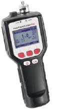 |
|
|
|
Headspace Sampling Device - Flame Ionization Detector (FID) |
|
|
|
Groundwater Pumping and Sampling Devices - Combustible Gas Indicator (CGI)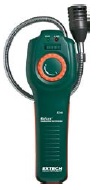 |
|
|
|
Groundwater Pumping and Sampling Devices - Draeger tubes (detector tubes)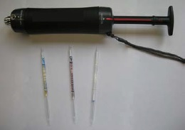 |
|
|
|
Groundwater Pumping and Sampling Devices - Bailer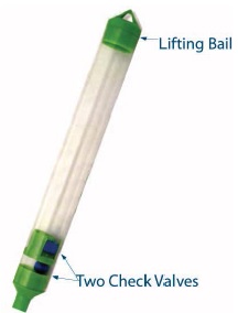 |
|
|
|
Groundwater Pumping and Sampling Devices - Thief Sampler (Kemmerer)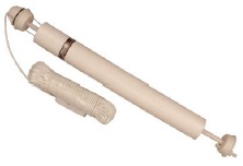 |
|
|
|
Groundwater Pumping and Sampling Devices - Passive Diffusion Sampler (sometimes called a Passive Diffusion Bag Sampler)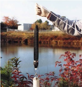 |
|
|
|
Groundwater Pumping and Sampling Devices - HydraSleeve Sampler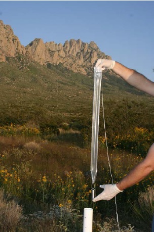 |
|
|
|
Groundwater Pumping and Sampling Devices - Snap Sampler |
|
|
|
Groundwater Pumping and Sampling Devices - Bladder Pumps |
|
|
|
Groundwater Pumping and Sampling Devices - Inertial Lift Pump |
|
|
|
Groundwater Pumping and Sampling Devices - Peristaltic Pump |
|
|
|
Groundwater Pumping and Sampling Devices - Electric Submersible Centrifugal Pump |
|
|
|
Groundwater Pumping and Sampling Devices - Double Acting Piston Pump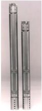 |
|
|
|
Groundwater Pumping and Sampling Devices - Progressing Cavity Pump (also known as Helical Rotor, or Moyno-type pump)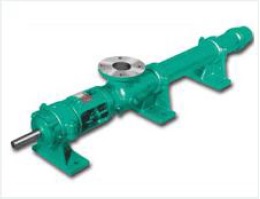 |
|
|
|
Groundwater Pumping and Sampling Devices - Electric Submersible Gear Pumps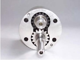 |
|
|
|
Groundwater Pumping and Sampling Devices - Gas displacement pump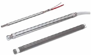 |
|
|
|
Specialty Groundwater Sampling Equipment
There are various groundwater sampling devices used with direct push and cone penetration testing (CPT) equipment. The devices provide immediate samples for water chemistry in a portion of an overburden aquifer. These devices also reduce the costs associated with well construction, purging issues and the time required to obtain samples. Examples of these devices include:
- Exposed screen samplers
- Sealed screen samplers
- Dual tube samplers
- Direct push, membrane interface probes (MIP) for semi-quantitative data on VOC concentrations in the subsurface
Reminder: If the person uses direct push or CPT methods to construct holes for the purposes of sampling groundwater, measuring water levels or obtaining other information with respect to groundwater or an aquifer, s/he must meet the requirements of the Wells Regulation and the Wells section of the Ontario Water Resources Act.
Reminder: For further information on pumping, sampling and monitoring equipment, please refer to the following resources:
- Tables and graphics found in Chapter 9: Equipment Installation of Water Supply Wells – Requirements and Best Management Practices,
- Construction Dewatering and Groundwater Control, New Methods and Applications: Third Edition,
footnote 25 - Practical Handbook for Environmental Site Characterization and Ground-Water Monitoring: Second Edition,
footnote 26 and - Groundwater and Wells: Third Edition.
footnote 27
Groundwater Level and Other Monitoring Equipment
Accurate groundwater level data from test holes or dewatering wells allow for the determination and interpretation of static water levels, the potentiometric surface, groundwater flow direction and groundwater gradients. Groundwater level monitoring data are also used in combination with different tests (e.g., pumping tests, slug tests, packer tests) to determine aquifer characteristics.
There is a variety of monitoring equipment that can be used to obtain groundwater level data. The method and instruments used to collect and record changes in groundwater levels will vary depending on the purpose of the study and environmental conditions.
Records of Site Condition Regulation: Starting on July 1, 2011, amendments to O. Reg. 153/04 came into force and apply to phase two environmental site assessments (ESAs) conducted in support of records of site conditions (RSCs). For any such RSC submitted on or after this date, a qualified person conducting or supervising a phase two ESA is obligated to have met a number of specific requirements related to the measurement of groundwater levels in wells when determining groundwater direction as part of the phase two ESA. For further information, see O. Reg. 153/04.
Measurement Systems
There are two main equipment categories for the collection and recording of groundwater data:
- Manual measurements
- Continuous measurements.
Manual Measurement Systems
Manual groundwater level measurement systems are portable and used to obtain a snapshot of the groundwater level(s) at a well or site.
| Measurement Device | Description |
|---|---|
Electrical Probes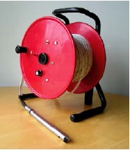 |
|
Interface Probe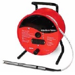 |
|
Pressure Transducer – Water Level Sensor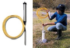 |
|
Bubbler Water Level Sensor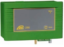 |
|
Popper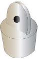 |
|
Acoustic Well Probe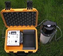 |
|
Ultrasonic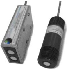 |
|
Radar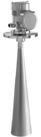 |
|
Laser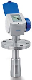 |
|
Manometer and Pressure Gauge under Flowing Conditions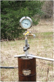 |
|
Wetted Chalk Tape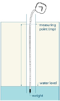 |
|
Air Line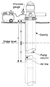 |
|
Float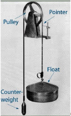 |
|
Reminder: Some of the devices in Table 12-2 can be used to measure the water level in a flowing well with a casing extension.
Continuous Measurement Systems
Continuous groundwater level measurement systems consist of equipment that provides for the automated collection of data at a set frequency. The automated collection of frequent and repeated groundwater level data is a necessary component of many hydrogeological investigations (e.g., baseline data). As with manual systems, the type of continuous measurement equipment used is dependent upon the specific data requirements. Examples of continuous measurement equipment are listed in the table below.
| Device | Description |
|---|---|
Float Recorder System |
|
Data Logger |
|
Figure 12-1: Satellite Telemetry System
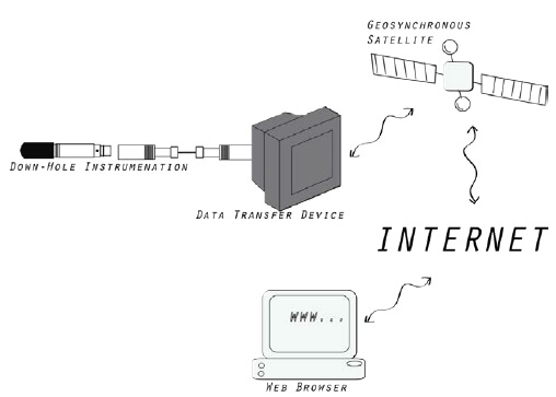
Figure 12-1 shows a digital communication system that allows real-time data acquisition between in situ measurements in a well and a computer network system. An example of this type of system is the MOECC Provincial Groundwater Monitoring Network (PGMN) which is used to record and transmit data on ambient groundwater conditions in real-time. Submersible sensors, such as pressure transducers and data loggers (see Table 12-2 and Table 12-3), and other monitoring equipment are used to measure groundwater conditions on a continuous basis.
Figure 12-2: A Provincial Groundwater Monitoring Network (PGMN) Well
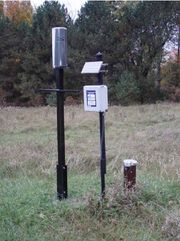
Figure 12-2 shows a monitoring well that is a part of the PGMN. It is equipped with an automatic pressure transducer and datalogger, a dedicated water quality sampling pump, a telemetry system and an optional rain gauge. The data are downloaded remotely by the Ministry of the Environment via the telemetry system. In some cases, the system is connected directly to a telephone cable. Equipment in this and other PGMN wells is powered by batteries and solar panels.
Other Field Monitoring Equipment
Obtaining measurements in the field can provide a good first indication of groundwater quality in a well or at a site. On-site field measurements also help to verify ambient groundwater conditions present during purging. It is important that some measurements, such as pH, dissolved oxygen and oxidation reduction potential (ORP), be taken in the field because exposure to atmospheric conditions may affect the laboratory results. Common parameters that can be measured in the field include the following:
- pH
- Oxidation Reduction Potential (ORP),
- dissolved oxygen
- turbidity
- temperature
- conductivity
- total dissolved solids (TDS)
Figure 12-3: A Multi-Parameter Water Quality Meter
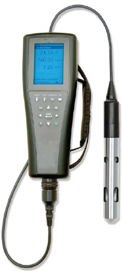
Figure 12-3 shows a multi-parameter water quality meter that can measure dissolved oxygen, conductivity, salinity, resistivity, TDS, pH, ORP, ammonium, nitrate, chloride and temperature if the proper probes are installed on the meter.
Inflatable Packer Systems
Inflatable packers can be installed in a well to conduct a packer test. See Chapter 13: Water Level Measurements, Aquifer Testing & Discharge Water Handling, "Hydraulic Conductivity Tests" section for further information on their use.
Figure 12-4: Inflatable Packer Prior to Installing and Inflating in a Well
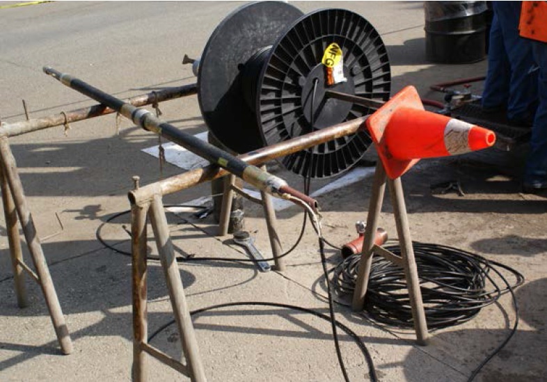
Figure 12-5: Cross-Section of a Packer Test Set-Up in a Well
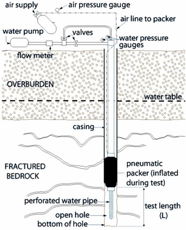
The figure is of a cross-sectional view of a well that has been installed through overburden and completed into bedrock. There are three main components to the figure; the well and associated stratigraphy and hydrostratigraphy, the packer equipment installed within the well, and the packer equipment above ground surface.
The well is shown as a casing that extends to just above ground surface, through the overburden, and partially into the fractured bedrock. The remainder of the well consists of an open hole within the bedrock. The water level is shown to be within the bottom half of the overburden unit. A number of fractures are illustrated within the bedrock.
The well is equipped with a single packer packer system. This includes a series of equipment at ground surface, as well as the packer within the well.
At ground surface, the packer is connected to a 2 separate systems: the air supply and the water pump.
A line with an air supply (compressed gas) and a pressure gauge connect to the pneumatic packer installed in the well in the bedrock formation. A water line, consisting of a water pump, a flow meter, a series of valves, pipes, and water gauges, attaches to the packer rods. The packer rod connects to the perforated water pipe located below the pneumatic packer. During a test, the pneumatic packer system in the well is inflated to isolate the section of the well being tested. Only the section below the packer is being tested. The test length is the distance from the bottom of the packer to the bottom of the open hole.
Reminder: This figure is not to scale, is for illustrative purposes for this chapter only and does not necessarily represent full compliance with other requirements found in the Wells Regulation.
Types of Pumps Used in Dewatering Wells
Various types of pumps are used for dewatering projects. Table 12-4 describes the most common types of pumps used for dewatering.
| Pump | Description |
|---|---|
Submersible Pump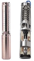 |
|
Hydraulic Submersible Pump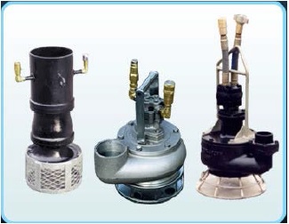 |
|
Turbine Submersible Pump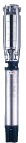 |
|
Turbine Vertical Line Shaft Pump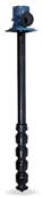 |
|
Suction Lift Pump for a Wellpoint System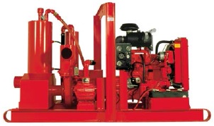 |
|
Below Ground Connections to Wells
It is recognized that below ground connections to well casing will not be made in most test holes and dewatering wells; however, any time connections are made to the well casing below ground, the requirements in the following sections apply.
If a trench is excavated and a test hole or dewatering well is constructed after the trench has been excavated, then:
- the original ground surface is considered the floor of the trench;
- the casing height and surface drainage requirements found in the Wells Regulation and Chapter 9: Completing the Test Hole or Dewatering Well Structure apply; and
- The Wells Regulation requirements in this section and in the "Installing Suitable Sealant into a Trench" section do not apply.
Drilled Test Holes and Dewatering Wells
The Wells Regulation: When making below ground connections to the casing of a drilled test hole or dewatering well the person constructing the well must use a well seal or pitless adapter (including pitless units) and make the connection watertight.
Pitless adapters or pitless units allow lateral pipes (i.e., waterlines) outside a drilled well casing to connect to drop pipes (waterlines) inside the well.
Reminder: A drop pipe usually extends from the connection at the pitless adapter to the pump or intake portion of the pumping equipment inside the well.
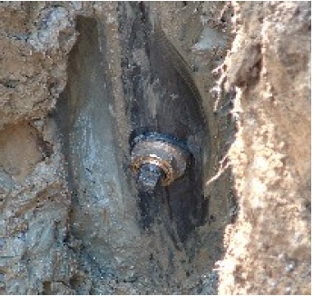
Pitless Adapters
A pitless adapter is primarily designed to make a watertight sanitary seal in a smooth casing below the frost level through the casing wall. A pitless adapter:
- connects downhole pumping equipment to piping in the trench, and
- allows the downhole pumping equipment to be easily removed while standing at the ground surface.
The size and number of holes through the casing depends on the design of the pitless adapter and pump equipment.
To ensure that the connection is watertight, it is necessary that a person installing a pitless adapter follows the manufacturer’s specifications and ensures that the adapter being installed is appropriate for the environment and the well design (e.g., casing size).
The Wells Regulation: The person constructing the well must not use a cutting torch to make an opening in the casing wall to accommodate a pitless adapter.
A cutting torch creates an opening that is too irregular to be made watertight.
Best Management Practice – Preparing to Install a Pitless Adapter
Before installing the pitless adapter, the person constructing the well should cut the hole in the casing wall with a hole saw and should remove metal burs along the open hole’s edges to ensure that the pitless adapter creates a watertight fit to the casing.
A cordless drill helps eliminate the possibility of electrocution.
Figure 12-6: Pitless Adapter
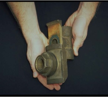
Figure 12-7: Pitless Adapter Installed
Best Management Practice – Reviewing Pitless Adapter Standards
The person installing the equipment in the well should review the standards and recommendations found in the Water Systems Council brochure titled WSC Performance Standards and Recommended Installation Procedures for Sanitary Water Well Pitless Adapters, Pitless Units, and Well Caps
The brochure is available through the Water Systems Council website.
Best Management Practice – Connecting Waterlines above the Ground Surface in a Drilled Well
If the person cuts a hole in a drilled well casing above the ground surface, the person should ensure that, at all times, the connection to the casing is watertight.
Sanitary Well Seals
Sanitary well seals are primarily designed to create a watertight seal where the waterlines, air vents and electrical lines extend through the top of the well casing.
A sanitary well seal consist of a neoprene gasket between two steel plates. When the two plates are tightened together, the neoprene gasket expands, which seals waterlines, air vents, electrical lines and the casing.
When installing a sanitary well seal, it is necessary to follow the manufacturer’s specifications to ensure that the connection is watertight and the appropriate seal is installed for the environment and the well design.
Figure 12-8: Sanitary Well Seal
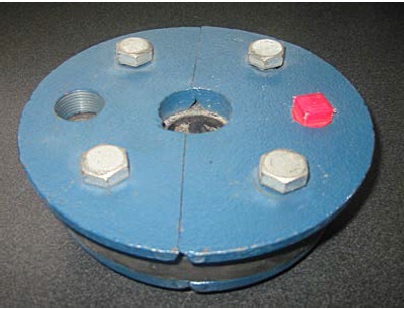
The photograph shows an example of one kind of sanitary well seal. In this case, a blue steel plate is underlain by a black neoprene gasket. The gasket is underlain by another blue steel plate. One waterline can pass through the centre of the well seal. An air vent can be threaded onto the seal on the left side of the well seal. The red plug can be removed on the right side of the well seal to allow for an electrical line or other equipment through the well seal. By tightening the four steel bolts on top of the well seal, the two plates are tightened together expanding the neoprene gasket. The squeezed gasket seals the waterline, electrical line and the casing. The well seal is typically found at the top of the well casing. Other sanitary well seals have two holes for two waterline installations used in jet pumps.
Other Test Holes and Dewatering Wells
The Wells Regulation: When making a below ground connection to a well casing of a well other than a drilled well (e.g., constructed by boring, digging, augering or direct push equipment), the person constructing the well must make the connection watertight with a durable bonding material.
Any bonding material must be durable and adhere to the side of the casing and the waterline. Also, the bonding material must not impair the water quality.
Large diameter corrugated conduits or other pipe used to protect waterlines in trenches should not extend through the well casing. Only properly connected and sealed waterlines and electrical lines should extend through the casing.
It is important to know and follow the manufacturers’ specifications for bonding material and installation of waterlines through the well casing (e.g., fiberglass, galvanized and concrete).
Best Management Practice – Waterline Connection through Concrete Casing
A concrete tile pitless adapter should be installed when a connection to a waterline is made through the side of a concrete casing.
As an alternative, a steel supporting bracket can be used on the inside of the well casing. The bracket will attach to the pitless adapter and allow the lateral pipe to extend through the casing and into the well. The horizontal pipe connection to the casing must be sealed with hydraulic cement or other durable bonding material that will not impair the water quality.
Reminder: Hydraulic cement looks like other cement and it is used to stop water leaks through cracks and faults in concrete. Tape should be used to hold the cement in the connection area while it sets (cures).
Best Management Practice – Connecting Waterlines above the Ground Surface in a Well that is Not a Drilled Well
If the person cuts a hole into a casing above the ground surface of a well that is not a drilled well, the person should ensure that, at all times, the connection to the casing is watertight.
Installing Suitable Sealant Into a Trench
It is recognized that this will not apply to most test holes and dewatering wells. However, when below ground connections are made to a casing of a well, the following will apply to any excavation created.
The Wells Regulation: When making a below ground connection to the casing of a well, the person constructing the well must fill any outside excavation with suitable sealant extending from the casing a minimum distance outward of 20cm (8 inches) and extending from the bottom of the excavation to within 20cm (8 inches) of the ground surface.
The person excavating the trench should consider the direction of the trench and the proximity to potential sources of contamination as the trench can act as a preferential pathway for contaminants.
Best Management Practice – Sealing the Excavation
It is important to consider the direction of the trench and the proximity to potential sources of contamination as the trench can act as a pathway for contaminants to migrate to the well site or building.
If suitable sealant has been installed to a horizontal distance that is greater than 20 cm (8 inches) from the well casing (during the filling of the well’s annular space), then the trench should be backfilled with suitable sealant from the outside of the well casing to at least the same distance as the original sealant.
When backfilling the remainder of the trench, the person installing the equipment should:
- place fully hydrated bentonite berms at set intervals at the bottom of the trench and over the top of the waterlines and electrical wires to help minimize horizontal movement of water and contaminants along the trench, and
- backfill the trench with clean soil that can withstand the weight of persons, animals and vehicles, and that will not promote the movement of water.
If a larger diameter pipe is used to house the waterline and electrical wires from the well to a structure, the person installing the equipment should:
- stop the larger diameter pipe before the outside of the building and before the trench’s sealant at the well to prevent surface water and foreign materials from entering the well site or building,
- ensure the larger diameter pipe is not perforated and is strong enough to withstand corrosion and the weight of the overlying materials, and
- take adequate precautions to prevent water or foreign materials from entering the larger diameter pipe and from being directed toward any building, foundation or the well.
Venting the Well
The purpose of the air vent is to allow the well to breathe, which allows equalizing pressures (i.e., when water is drawn out, air goes in so the column of water remains at atmospheric pressure at all times) and the venting of natural gases.
Venting After New Test Hole and Dewatering Well Construction
The Wells Regulation: When a new dewatering well is constructed, the well must be vented to the outside atmosphere in a manner that will safely disperse all gases. This requirement does not apply to a:
- test hole, or
- dewatering well where the casing will be used to transmit water out of the well (e.g., driven point dewatering system).
Reminder: Venting may be problematic for some test hole or dewatering well applications such as:
- test holes designed to collect both gas and water samples
- dewatering wells that flow.
Venting exemptions allow for such applications.
Reminder: Flowing wells are not exempt from the regulatory requirement for venting unless the casing is used in some form to transmit water out of the well or the well is a test hole. A mechanical or inflatable packer with an air release valve and air vacuum relief valve may be installed to vent the well to allow air into and out of the well during pumping (see Figure 11-8 and Figure 11-9 of Chapter 11: Flowing Test Holes & Dewatering Wells for further information).
Venting During Pump Installation in Drilled Test Holes and Dewatering Wells
The Wells Regulation: Unless exempt, if a pump is installed in a drilled test hole or dewatering well, the person constructing the well must install an air vent on the well and meet the following requirements:
- The air vent must have a minimum inside diameter of:
- 0.3 cm (0.12 inches) for a well casing that has an inside diameter <12.7 cm (5 inches), or
- 1.2 cm (0.47 inches) for a well casing that has an inside diameter ≥12.7 cm (5 inches).
- In an area where there is potential for flooding, the air vent must extend above the maximum anticipated flooding level and not less than 40 cm (16 inches) above the ground surface.
- On a drilled well in a new well pit, the air vent must extend a sufficient height above the covering of the well pit.
- The open end of the air vent must be shielded and screened to prevent the entry of foreign materials (e.g., insects) into the well.
Reminder: A vent with a larger inside diameter will reduce the risk of the vent freezing during periods of extreme cold temperatures.
To assist persons who are designing various test holes and dewatering wells, the Wells Regulation provides an exemption to the venting size and other venting requirements of pump installation for a drilled test hole or dewatering well. The vent sizes and other venting requirements of pump installation for a drilled test hole or dewatering well do not apply:
- to an uncased test hole or dewatering well
- to a test hole or dewatering well where the equipment installation is exempt from the Wells Regulation (e.g., measuring the water level in a well using a water level meter) or where the equipment is installed in an exempted well (see Chapter 3: Exemptions: Wells, Activities & Experienced Professionals for further information)
- to a test hole or dewatering well with a flush-mounted watertight commercially manufactured well cover where there is no potential hazard from natural gas or any other gas
- to a test hole or dewatering well with a well pit where there is no potential hazard from natural gas or any other gas. However, an air vent line must be installed on the new drilled well in a new well pit and must extend above the cover of the well pit
Best Management Practice – When Gases are Encountered
Anyone constructing a well in an area where there is the potential to encounter natural gas or other gases should consider retaining the services of a Professional Geoscientist or Professional Engineer experienced in groundwater and test holes or dewatering wells producing naturally occurring or other gases. The Professional Geoscientist or Professional Engineer should:
- assess the well and the hydrogeology and geology around the well,
- provide the well owner with written recommendations, and
- confirm that the recommendations have been implemented and address the gas concerns at the site.
Best Management Practice – Venting a Well Pit
Any well, even a well in a well pit, should be vented to disperse gases.
A well in a well pit should be vented with a shielded and screened vent.
Best Management Practice – Venting a Flush-Mounted Well Pit (Vault)
In an area where the potential exists for gases to build up in a flush-mounted well pit (vault), a Professional Geoscientist or Professional Engineer should be retained to design an appropriate venting system to prevent explosive and hazardous conditions within the well head, well pit and at the well site.
It is important that the design include detection equipment and/or alarm systems.
Figure 12-9: Vented Well Plug
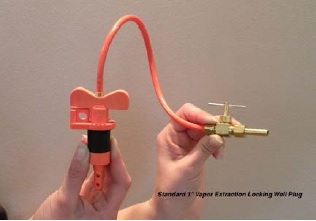
Figure 12-9 shows an air vent extending through the centre of a locking well plug.
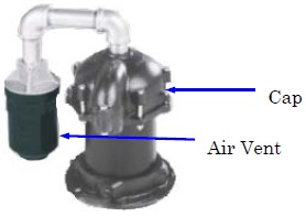
Figure 12-10: Air Vent Extended Through A Well Plug
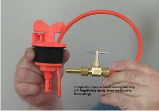
Figure 12-10 shows a similar design to Figure 12-9 except the air vent does not extend through the centre of the well plug. These vented well plugs can be used for drilled test holes where pumping equipment has been installed. A shut-off valve has been attached to the air vent to allow for vapour extraction and to prevent the entry of surface water and other foreign materials into the test hole.
Figure 12-11: Drilled Well With a Vented Vermin-Proof Cap
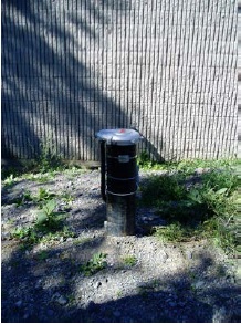
Figure 12-12: Vent Location on Underside of Three Vermin-Proof Caps Commonly Used in Ontario
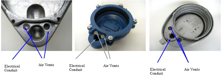
Figure 12-13: Watertight Cap With Extendable Screened Air Vent Located Above the Well Cap
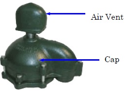
Figure 12-14: Watertight Cap With Snorkel Vent Used to Prevent Flood Water from Entering the Top of a Drilled Well
Wells Encountering Gas
The Wells Regulation: Where a well is constructed and natural gas is encountered, the person constructing the test hole or dewatering well must immediately notify the well purchaser, the owner of the land on which the well is situated and the Director that the condition exists.
If a test hole or dewatering well is producing a natural gas or other gas and the gas is detected, the well owner must do at least one of the following:
- Abandon the well and take the necessary steps to properly plug and seal the well,
- Take the necessary measures to manage the gas in a way that prevents any potential hazards and ensure the measures are functional at all times, or
- Seek the written consent from the Director to allow for the continued use of the well (see Chapter 16: Abandonment: When to Plug & Seal Test Holes & Dewatering Wells).
For example, a waste disposal site where gases are expected will need to be carefully managed, with special precautions and procedures to prevent harm.
Reminder: See the Encountering Gas, Contamination and Water Quality Problems section of Chapter 6: Constructing the Hole, Casing & Covering the Test Hole or Dewatering Well for further information and best management practices dealing with natural gas.
Best Management Practice – Notification for Gases Other than Natural Gas
When "other" gases (e.g., benzene gas from a petroleum hydrocarbon spill) that cause, or may cause, adverse effects on public health and/or the natural environment are encountered, then the person constructing the well should notify the Spills Action Centre at
Well Caps and Covers
The purpose of well caps and covers is to prevent the entry of surface water and other foreign material into the well. The following requirements will apply to covering the well unless an exempted activity is being performed.
The Wells Regulation: If a well is constructed by a method other than boring (augering) or digging, the person constructing the well must seal the top of the casing with a commercially manufactured vermin-proof well cap.
For example, wells constructed by drilling, jetting and driving are captured by this well cap requirement.
The Wells Regulation: If a well is constructed by boring and digging, the person constructing the well must cover the top of the casing with a solid, watertight well cover that prevents the entry of surface water and other foreign materials.
Preventing the entry of other materials includes designing the well cover to be of sufficient strength to withstand any known weight that might be applied to the well cover or cap, and the freezing and thawing action that may cause the cover to break.
Reminder: It is important that anyone constructing a well installs the well cover or cap to the design specifications provided by the manufacturer and ensures that the design will work for the environment and the well.
Records of Site Condition Regulation: Starting on July 1, 2011, amendments to O. Reg. 153/04 came into force and apply to phase two environmental site assessments (ESAs) conducted in support of records of site conditions (RSCs). For any such RSC submitted on or after this date, the qualified person conducting or supervising the ESA must ensure that precautions are taken to minimize the potential for cross-contamination or contamination through preferential pathways when sampling of groundwater is being undertaken to demonstrate if the applicable site condition standard for a contaminant has been met or not.
Records of Site Condition Regulation: There are many additional sampling, analysis and other requirements for phase two ESAs. Please refer to O. Reg. 153/04 for the details.
Covering the Test Hole or Dewatering Well
Dug or Bored (Augered)
The person constructing the well must cover the top of the well casing with a solid watertight well cover so that surface water and other foreign materials cannot enter into the well. This includes fastening and securing the cover to reduce the risk of children being able to access the well.
Figure 12-15: Dug Well With a Solid Well Cover
For additional information on covers for dug or bored wells see the "Well Caps and Covers" section in Chapter 9: Equipment Installation of the Water Supply Wells: Requirements and Best Management Practices manual (available on Ontario.ca).
Drilled or Other
The person constructing the well must seal top of a well casing that is not constructed by digging or boring with a commercially manufactured vermin-proof well cap. This includes a properly installed and sealed sanitary well seal and a watertight and airtight well cap for a jetted or driven point well.
Reminder: Waterlines sealed to the top of the casing and to a pump under a vacuum are considered vermin-proof well caps for dewatering systems using shallow point wells.
Best Management Practice - Characteristics found in a quality monitoring well plug
There are many plugs on the market for sealing monitoring wells, some locking and some not.
Below are some characteristics that should be inherent in the design and materials used in the manufacturing of a well plug for a test hole.
- Made of a glass filled nylon resin
- Does not contain metals
- Has a bright safety colour with American Petroleum Institute (API) warning label
- Has a domed top so liquids will run off the plug and not pool on the top of the plug or well casing
- Is liquid/ pressure tight. This does not preclude the plug from having a closable vent, see Figure 12-9 and Figure 12-10
- Has a dual-purpose one-piece liquid/air tight rubber gasket that has a broad range of chemical resistance and absorption properties
- Has one or two tethering/tool attachment(s) at the base allowing equipment, such as a dedicated bailer or pressure transducer, to be placed within the casing while also allowing a locking device to be installed on the outside of the J-plug
- Is tamper resistant
- Is made with a silicone additive that acts as a liquid repellant
- Has a product warrantee
Figure 12-16: Vermin-Proof Well Cap
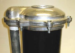
Figure 12-17: Vermin-Proof Cap And Conduit
Figure 12-18: Snap on Caps for Monitoring Wells
Figure 12-19: PVC Slip on Cap for Monitoring Wells
Reminder: Care should be taken when using a PVC slip on cap as it may not be watertight under certain circumstances.
Reminder: See Figure 12-9 and Figure 12-10 on page 58 for photographs of locking J-plugs with air vents.
Figure 12-20: Dewatering Well System With Pressure Lines Connected to the Top of the Casings
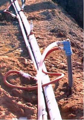
Figure 12-20 shows an eductor well dewatering system with twin pressure lines connected to the top of the well casings
Flush-Mounted Well Cover
In certain circumstances, a well can be completed with a flush-mounted watertight commercially manufactured well cover.
The Wells Regulation: Where the well is located in an area where vehicle or pedestrian traffic is likely to pass directly over the well, the person constructing the well can complete it with a flush-mounted watertight commercially manufactured well cover that must be:
- sufficient to prevent entry of surface water and other foreign materials into the well, and
- sufficiently strong, durable and properly installed to protect the well from damage, or the cover must be covered with a metal plate that is sufficiently large and sufficiently strong, durable and properly installed to protect the well cover and the well from damage.
Depending on the type of well, the flush-mounted cover must also meet the well cover or well cap requirements for dug, bored, drilled or other wells if it is used to cover or seal the top of the well casing.
Reminder: For an example of a flush-mounted well cover, see Figure 9-4: An Example of a Flush-Mounted Watertight Commercially Manufactured Well Cover in Chapter 9: Completing the Test Hole or Dewatering Well Structure.
Alternative to a Well Cap or Cover
The Wells Regulation: The cover, cap or seal is not required if all of the following criteria are met:
- a floor is constructed around or adjacent to the casing of the well,
- a pump (includes associated equipment such as waterlines) is installed above or adjacent to the well (this scenario would include wells with a vertical turbine pump, hand pump or other type of pump positioned directly over the casing),
- the top of the casing is shielded in a manner sufficient to prevent entry of any material that may impair the quality of the water in the well, and
- the casing of the well is extended to at least 15 cm (6 inches) above the floor that is constructed around or adjacent to the casing of the well.
Reminder: This type of pump arrangement is not likely to be encountered for most test holes or dewatering wells.
Figure 12-21: example of a well not requiring a cover, cap, or seal: vertical turbine pump installed directly over the well
Casing Height and Mounding
The Wells Regulation: Unless exempt, any person installing equipment in a well must ensure that the casing height, mounding and surface drainage meet requirements discussed in Chapter 9: Completing the Test Hole or Dewatering Well Structure.
Permitted Well Pits for Test Holes or Dewatering Wells
In most circumstances, well pits are not allowed to be constructed on new or existing test holes or dewatering wells.
The Wells Regulation: In only two circumstances, however, a person constructing a new test hole or dewatering well may be allowed to finish the well with a well pit. The Wells Regulation provides options for the construction of permitted well pits depending on the location of the well, the type of equipment used to construct the well and the well’s purpose. The two permitted circumstances are:
- The Wells Regulation permits the construction of a new test hole or dewatering well with a well pit as long as the well is constructed with diamond drilling equipment in connection with mineral exploration.
- The Wells Regulation permits the construction of a test hole or dewatering well with a new well pit or the addition of a new well pit to an existing test hole or dewatering well if the well is located where vehicle or pedestrian traffic is likely to pass directly over the well and the well is completed with a flush-mounted well cover in accordance with the Wells Regulation.
Along with the information provided in this section, see the "Plainly Stated" section in this chapter for further requirements and information on permitted well pits including flush-mounted well pits (vaults).
A well pit is designed to:
- contain the upper portion of a drilled or driven test hole or dewatering well,
- prevent the upper portion of the well and waterlines from freezing, and
- allow access to the top of the well.
Well pits were the preferred choice of pump installers when installing waterlines out of the top of a drilled well to a building until the widespread use of submersible pumps, pitless adapters and pitless units began.
Flush-mounted well pits (vaults) continue to be the preferred choice for test hole and some dewatering well installations where the area is subject to traffic or where an above-grade casing would be a hazard, nuisance or subject to damage. This type of completion is set into the surface seal before it has cured and is installed around the well casing, which has been cut off below grade and properly capped or covered. The flush-mounted well pit (vault) structure must be durable and is generally constructed with steel, aluminum or a high-strength composite plastic material. Flush-mounted test holes or dewatering wells should not be installed in low-lying areas that are subject to ponding or flooding. Some examples of flush-mounted well pits (vaults) are shown in Figure 12-24 to Figure 12-27.
There are many problems associated with well pits in Ontario, such as:
- surface water can pond around the casing and above the top of drilled wells,
- large openings in the well pit’s walls can allow surface water and foreign materials to enter the pit and possibly, the top of the well, impairing the well water,
- the structure can be unsafe,
- the structure can be subject to frost heave,
- flush-mounted well pits (vaults) may be damaged by snow removal or other vehicles, and
- surface water can enter the well and cause groundwater mounding.
Reminder: A well pit is considered a confined space. There are many serious risks and hazards associated with this type of confined space including electrocution, asphyxiation, physical hazards such as drowning or falling, presence of poisonous gases and explosive gases. Although much smaller, flush-mounted well pits (vaults) can present similar hazards (e.g., gas and physical hazards). All required preventative measures when entering a confined space must be undertaken prior to accessing or entering any well pit. Further requirements are found in Ontario Regulation 632/05 (Confined Spaces) made under the Occupational Health and Safety Act.
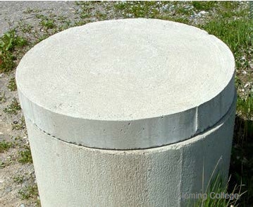
Figure 12-22: A Typical Flush-Mounted Well Pit (Vault)
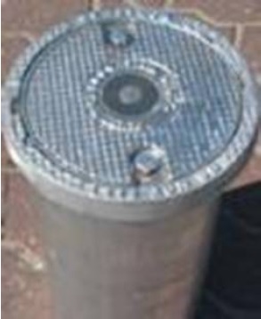
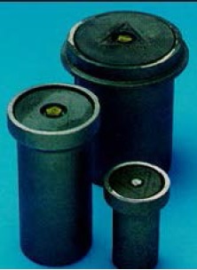
Figure 12-23: Three Different Sizes of Flush-Mounted Well Pits (Vaults)
Well Pit Walls (Or Casing)
The following Wells Regulation requirements apply when a new permitted well pit, including a flush-mounted well pit (vault), is constructed for a test hole or dewatering well.
The person constructing the well must:
- consider the walls of the well pit as "casing" and
- meet the casing requirements found in Chapter 6: Constructing the Hole, Casing & Covering the Test Hole or Dewatering Well and Chapter 9: Completing the Test Hole or Dewatering Well Structure in this manual.
For example, if a permitted well pit is installed for a test hole or dewatering well, the person constructing the well must ensure that the well pit casing is:
- made of new material, unless it is scheduled to be abandoned within 180 days of completion of the structural stage,
- clean and free of contamination, and
- watertight, including any seams.
As another example, if concrete material is used as well pit casing, the person constructing the well must ensure that the:
- casing sections are properly aligned so that the joints are flush and the casing is centred,
- casing is commercially manufactured and fully cured, and
- joints between casing sections are sealed with a mastic sealing material (e.g., butyl rubber material) approved by the NSF International that remains pliable and waterproof.
Surface Drainage for a Well Pit
The following Wells Regulation requirement applies when a new permitted well pit, including a flush-mounted well pit (vault), is constructed for a test hole or dewatering well.
The person constructing the test hole or dewatering well must ensure that surface water drainage is such that water will not collect or pond in the vicinity of, or within, a permitted well pit’s casing.
Flush-mounted well pits (vaults) for test holes or dewatering wells should not be installed in low-lying areas that are subject to ponding or flooding.
Creating And Filling The Well Pit’s Annular Space
Unless exempt, the following Wells Regulation requirements apply when a new permitted well pit, including a flush-mounted well pit (vault), is constructed for a test hole or dewatering well.
The person constructing the well must:
- ensure that the entire new well pit, from the bottom of the well pit to the ground surface, is constructed with a diameter that is at least 7.6 cm (3 inches) greater than the outside diameter of the well pit’s walls (or casing).
- fill any annular space outside the permitted well pit’s casing, from the bottom of the well pit to the ground surface, with suitable sealant.
- use a suitable sealant with the appropriate structural strength to support the weight of persons and vehicles that may move over the area after it is filled.
If the suitable sealant contains cement, the person constructing the well must:
- allow the cement to set according to the manufacturer’s specifications or for 12 hours, whichever is longer; and
- if, after setting, the sealant has settled or subsided, top up the cement to the ground surface.
The Wells Regulation exempts a person constructing a test hole or dewatering well that is scheduled to be abandoned within 180 days of completion of the structural stage from the above annular space sealing requirements for a permitted well pit. The regulatory exemptions regarding test holes and dewatering wells, that are scheduled to be abandoned within 180 days of completion of their structural stage, allow for well technicians, engineers and geoscientists to use their professional expertise to design and install test holes and dewatering wells on a case by case basis.
Best Management Practice – Protection from Frost Heave for Flush-Mounted Well Pits (Vaults)
To reduce frost heave, concrete should be used as a suitable sealant in the annular space and below the flush-mounted well pit (vault). The concrete should extend at least 10 cm (4 inches) from the outside of the vault and at least 30 cm (12 inches) below the frost line.
Records of Site Condition regulation: Starting on July 1, 2011, O. Reg. 153/04 prescribes that the provisions of the Ontario Water Resources Act and of Regulation 903 of the Revised Regulations of Ontario, 1990 (Wells) made under that Act, that would apply to a test hole but for section 1.1, and subsections 13 (2), 14.1 (2), 14.2 (3), 14.3 (2), 14.4 (4) and 14.5 (3) of that regulation, apply to a monitoring well installed for the purpose of,
- a phase one environmental site assessment; and
- a phase two environmental site assessment.
Implications for the Qualified Person
The qualified person shall ensure that the phase two ESA is conducted in accordance with the requirements stated above.
Implications for the Annular Space of a Well Pit
With respect to a well pit’s annular space size and filling, the above requirement in O. Reg. 153/04 means that, if a new test hole is constructed, is scheduled to be abandoned not later than 180 days after the completion of its structural stage, and is to be used as a monitoring well in an ESA for a record of site condition, then:
- the annular space size and filling exemptions for a test hole’s well pit stated in this section do not apply, and
- the annular space size and filling requirements for a test hole’s well pit stated in Table 7-1 of Chapter 7: Annular Space & Sealing do apply.
Reminder: The above requirement in O. Reg. 153/04 also affects obligations relating to casing material, well screen material and shallow works for monitoring wells. See Chapter 3: Exemptions: Wells, Activities & Experienced Professionals and Chapter 6: Constructing the Hole, Casing & Covering the Test Hole or Dewatering Well for further information.
Records of Site Condition regulation: Please refer to O. Reg. 153/04 for RSC requirements.
Reminder: To understand the term "monitoring well" as defined in the Records of Site Condition regulation see O. Reg. 153/04 and Chapter 2: Definitions & Clarifications, Table 2-2.
Well Pit Floor
The following Wells Regulation requirement applies when a new permitted well pit, including a flush-mounted well pit (vault) is constructed for a test hole or dewatering well. The person constructing the well must cover the floor of the new well pit with at least a 10 cm (4 inches) thick layer of suitable sealant that when set to a solid state will be capable of supporting the weight of a person.
Best Management Practice – Well Pit Floor
It is important that the suitable sealant used to construct the well pit floor be able to withstand the pumping of any water from the floor of the well pit. Some sealants, such as bentonite, may erode during pumping of water from the well pit’s sump, whereas properly cured concrete will not likely be removed during the pumping of water with a sump pump in any well pit sump hole.
Well Pit Cover
The following Wells Regulation requirements apply when a new permitted well pit, including a flush-mounted well pit (vault), is constructed for a test hole or dewatering well.
The person constructing the well must cover of the well pit with a solid, watertight cover, sufficient to prevent the entry of surface water and other foreign materials into the well pit.
In the case of a permitted flush-mounted well pit (vault), the person constructing the well must cover the well pit with, a watertight, commercially manufactured cover that is:
- sufficient to prevent the entry of surface water and other foreign materials into the well and
- sufficiently strong, durable and properly installed to protect the well from damage, or covered with a metal plate that is sufficiently large and strong, durable and properly installed to protect the well and well cover from damage.
The following Wells Regulation requirement applies when a new permitted well pit, other than flush-mounted well pit (vault), is constructed for a new test hole or dewatering well that has been constructed with diamond drilling equipment in connection with mineral exploration.
The person constructing the well must fasten and secure the cover of the well pit in a manner that will make it difficult for children to remove it.
The Wells Regulation exempts the person constructing a permitted flush-mounted well pit (vault) for a test hole or dewatering well from the fastening and securing requirements because other requirements have been put in place to protect the well from damage, surface water and other foreign materials.
The purpose of a metal plate, if used as a cover for a flush-mounted well pit (vault), is to bridge the top of the well and transfer any traffic loadings (whether from vehicles, pedestrians or animals) horizontally so that the top of the well or well pit structure is not subjected to the weight of the vehicles or people.
Reminder: New flush-mounted well pits (vaults) are only allowed in areas that are subject to vehicular and pedestrian traffic.
Best Management Practice – Flush-Mounted Well Pit (Vault) Material
It is important for the flush-mounted well pit (vault) structure and cover to be made of material that is rated for traffic (e.g., steel, aluminum or high strength composite plastic).
Keeping the Well Pit Dry
The following Wells Regulation requirements apply when a new permitted well pit, other than flush-mounted well pit vault, is constructed for a new test hole or dewatering well that has been constructed with diamond drilling equipment in connection with mineral exploration.
Sump Pump
The person constructing the well must ensure that the new well pit is kept dry by means of a sump pump. This could also mean a sump hole would need to be installed into the floor of the well pit.
Drainage Pipe
If the water table is substantially lower than the floor of a permitted well pit, the person constructing the test hole or dewatering well may ensure that the new well pit is kept dry by means of a drainage pipe that:
- has a one-way valve to allow water to discharge from the pit but prevents surface water and other foreign materials, including insects and animals, from entering the well pit,
- passes through the layer of sealant, and
- allows water to discharge near the perimeter of the well pit.
As indicated in the best management practice titled "Well Pit Floor" in this section, the suitable sealant used to construct the well pit sump hole should be able to withstand the pumping of any water from the well pit.
The Wells Regulation exempts the person constructing a permitted flush-mounted well pit (vault) for a test hole or dewatering well from the sump pump or drainage pipe requirements. The regulatory exemption regarding test holes and dewatering wells with flush-mounted well pits (vaults), allows for well technicians, engineers and geoscientists to use their professional expertise to design and install test holes and dewatering wells on a case by case basis.
Best Management Practice – Keeping Flush-Mounted Well Pit (Vault) Dry
It is important to design and construct the flush-mounted well pit (vault) to ensure that it is kept dry at all times.
Some considerations for keeping a flush-mounted well pit (vault) dry are:
- where possible, a drain with a one-way valve that passes through the layer of sealant on the floor of the well pit should be installed,
- the flush-mounted well pit (vault) should not be installed in low-lying areas that are subject to ponding or flooding,
- a flexible gasket should be installed at the point where the flush-mounted well pit (vault) cover attaches to the well pit structure, and
- an expanding well casing cap that does not have a vent should be installed where there is no potential risk of gas build up to further prevent surface water from entering a test hole or dewatering well within a flush-mounted well pit (vault).
Best Management Practice – Design Considerations for Flush-Mounted Well Pits (Vaults) on Paved Surfaces
If a test hole or dewatering well is constructed in a roadway, road allowance or other paved surface, the flush-mounted well pit (vault) should extend from the ground surface to at least 30 cm (12 inches) below the gravel sub-grade. The suitable sealant should also extend slightly deeper than the bottom of the well pit casing to reduce the risk of water backing up inside the enclosure.
Test Hole or Dewatering Well Casing Height Above Well Pit Floor
The following Wells Regulation requirement applies when a permitted well pit, other than flush-mounted well pit vault, is constructed with or added to a test hole or dewatering well that has been constructed with diamond drilling equipment in connection with mineral exploration.
The person constructing the well must extend the top of the test hole or dewatering well casing at least 40 cm (16 inches) above the floor of the new well pit.
The Wells Regulation exempts the person constructing a new permitted flush-mounted well pit (vault) for a test hole or dewatering well from the casing height requirements. The regulatory exemption regarding test holes and dewatering wells with flush-mounted well pits (vaults), allows for well technicians, engineers and geoscientists to use their professional expertise to design and install test holes and dewatering wells on a case by case basis.
Best Management Practice – Minimum Height of Well Casing in a Flush-Mounted Well Pit (Vault)
To allow for the proper installation of the well cap or cover, the height of the casing should extend at least 10 cm (4 inches) above the flush-mounted well pit’s (vault’s) floor while providing the necessary clearance from the flush-mounted well cover.
Test Hole or Dewatering Well Cover/Seal & Vent in a Well Pit
The following Wells Regulation requirements apply when a new permitted well pit, other than flush-mounted well pit vault, is constructed for a test hole or dewatering well that has been constructed with diamond drilling equipment in connection with mineral exploration.
The person constructing the well must:
- seal the top of the drilled well casing inside the new well pit with a commercially manufactured sanitary well seal and
- provide an air vent line from the commercially manufactured sanitary well seal to above the cover of the new well pit.
The Wells Regulation exempts the person constructing a permitted flush-mounted well pit (vault) for a test hole or dewatering well from the sealing and venting requirements because other requirements have been put in place to protect the well from damage, surface water and other foreign materials.
Reminder: The top of a test hole or dewatering well inside a new well pit, including a new flush-mounted well pit (vault), must be sealed with a commercially manufactured vermin-proof cap or solid watertight well cover. A commercially manufactured sanitary well seal is considered to be a commercially manufactured vermin-proof cap. For further information on covering a well, see the "Covering the Test Hole or Dewatering Well" section on page 61 of this chapter.
Reminder: To meet the above venting requirement in a permitted well pit, the air vent may extend through the side of the well pit casing (see Figure 12-28 in this chapter).
Best Management Practice – Shield and Screen Air Vent Line on Well Pit
It is important that the well’s air vent in a well pit be shielded and screened in a way that prevents the entry of surface water and other foreign materials.
If there is a potential for hazardous gases to build up in a flush-mounted well pit (vault), see the best management practices in the "Venting During Pump Installation in Drilled Test Holes and Dewatering Wells" section on page 56 of this chapter.
The venting requirements for a drilled test hole or dewatering well completed with a well pit, and where a pump is installed in the well, are detailed in the "Venting During Pump Installation in Drilled Test Holes and Dewatering Wells" section on page 56 of this chapter.
Figures of Installed Flush-Mounted Well Pits (Vaults) and Other Well Pits
Figure 12-24 to Figure 12-28 illustrate examples of the installation of flush-mounted well pits (vaults) and other well pits.
Reminder: The figures do not depict every circumstance. The diagrams are for illustrative purposes only, are not to scale and do not necessarily represent full compliance with other requirements found in the Wells Regulation.
Figure 12-24: Flush-Mounted Well Pit (Vault) For A New Well That Is Not Scheduled To Be Abandoned Within 180 Days
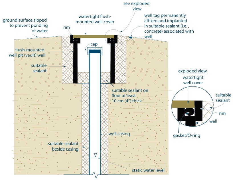
The figure is a cross sectional view of a well located within a well pit. The well and pit are installed at a high point, with the ground surface sloped to prevent ponding of water. The well consists of a well casing, suitable sealant, and well cap. The bottom of the well is not shown in the illustration. The water level is shown within the well but near the bottom of the illustration.
The well is located within a flush-mounted well pit (vault) in the ground. The well pit (vault) is approximately twice as wide as the well. The well pit, from the outside in, consists of suitable sealant, followed by the pit’s (vault’s) wall. The top of the pit is covered by a watertight flush-mounted well cover. The floor of the well pit (vault) consists of suitable sealant that is at least ten centimetres (four inches) thick. At ground surface, beside the well cover, is a well tag permanently affixed and implanted in suitable sealant (i.e., concrete). There is an exploded view of the top of the well pit wall.
Exploded View: The exploded view illustrates that the top of the well pit wall is a J or hook shape, with a gasket or O-ring seated inside the J. A watertight flush-mounted well cover sits on the gasket and the inner part of the pit wall.
- The hole diameter must be at least seven point six centimetres (three inches) greater than the diameter of the flush-mounted well pit vault.
- It is important that the gasket/O-ring be clean (including sand free) and greased to ensure a proper seal and to prevent cracking.
- The well cover must be commercially manufactured and sufficiently strong, durable, and well-insulated to prevent damage to the well.
- Cover should be fastened to prevent tampering.
- The suitable sealant beside the flush-mounted well pit wall and above the pit floor must provide appropriate structural strength to support the weight of persons or vehicles that may move over the well.
Reminder: This figure is not to scale, is for illustrative purposes for this chapter only and does not necessarily represent full compliance with other requirements found in the Wells Regulation.
Figure 12-25: Flush-Mounted Well Pit (Vault) With Metal Plate For A New Well That Is Not Scheduled To Be Abandoned Within 180 Days
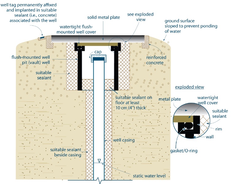
The figure is a cross sectional view of a well located within a well pit (vault), which is covered by a solid metal plate. The solid metal plate covering the well and pit has been installed at a high point, with the ground surface sloped to either side to prevent ponding of water. The metal plate is about twice as wide as the borehole, and extends over the well pit (vault), sealant, and into the native soil. The edge of the metal plate is set into a concrete form to secure the metal plate in place.
The well is located within the pit in the ground. The bottom of the well is not shown in the illustration. The water level is shown as a horizontal line within the well but near the bottom of the illustration.
The pit (vault) is approximately twice as wide as the well. From the outside in, the well pit (vault) consists of suitable sealant, followed by a flush-mounted well pit (vault) wall. The well pit (vault) is covered by a watertight flush-mounted well cover. The metal plate is located immediately above the well cover. The floor of the pit consists of suitable sealant at least ten centimetres (four inches) thick.
There is an exploded view of the top of the well pit wall.
Exploded View: The exploded view illustrates that the top of the well pit wall is a J or hook shape, with a gasket or O-ring seated inside the J, and the watertight flush-mounted well cover sits on the gasket and the inner part of the pit wall. The metal plate sits on top of the well cover, the outer part of the pit wall, and the sealant outside of the pit.
- The hole diameter must be at least seven point six centimetres (three inches) greater than the diameter of the flush-mounted well pit vault.
- It is important that the gasket/O-ring be clean (including sand free) and greased to ensure a proper seal and to prevent cracking.
- The well cover must be commercially manufactured and sufficiently strong, durable, and well-insulated to prevent damage to the well.
- Cover should be fastened to prevent tampering.
- The suitable sealant beside the flush-mounted well pit wall and above the pit floor must provide appropriate structural strength to support the weight of persons or vehicles that may move over the well.
Reminder: This figure is not to scale, is for illustrative purposes for this chapter only and does not necessarily represent full compliance with other requirements found in the Wells Regulation.
Figure 12-26: stronger flush-mounted well pit (vault) for a new well that is not scheduled to be abandoned within 180 days.
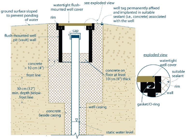
The figure is a cross sectional view of a well located within a well pit (vault), which is covered by watertight flush-mounted well cover. In this case, the well pit is located in an excavation. The excavation is at least 20 cm (8 inches) wider in diameter than the well pit (vault) and extends to a minimum depth of 30 cm (12 inches) below the frost line. The excavation in which the pit rests is filled with a concrete sealant.
The well and pit are installed at a high point, with the ground surface sloped to prevent ponding of water. At ground surface beside the well cover is a well tag permanently affixed and implanted in concrete sealant. There is an exploded view of the top of the well pit wall.
The well consists of a well casing, concrete sealant, and well cap. The bottom of the well is not shown in the illustration. The water level is shown within the well but near the bottom of the illustration.
The well is located within a pit in the ground. This pit, from the outside in, consists of concrete sealant at least ten centimetres (four inches) wide, followed by a flush-mounted well pit (vault) wall. The top of the well pit (vault) is covered by a watertight flush-mounted well cover. The floor of the pit consists of concrete sealant at least ten centimetres (four inches) thick. Exploded View: The exploded view illustrates that the top of the well pit wall is a J or hook shape, with a gasket or O-ring seated inside the J, and the watertight flush-mounted well cover sits on the gasket and the inner part of the pit wall.
Reminder: This diagram shows a well pit design that has increased structural strength and protection from frost heaving
Reminder: This figure is not to scale, is for illustrative purposes for this chapter only and does not necessarily represent full compliance with other requirements found in the Wells Regulation.
Figure 12-27: Flush-Mounted Well Pit (Vault) With Vent For A New Well That Is Not Scheduled To Be Abandoned Within 180 Days
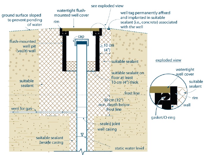
The figure is a cross sectional view of a well located within a well pit (vault), which is covered by watertight flush-mounted well cover. In this case, the well pit is located in an excavation. The excavation is at least 20 cm (8 inches) wider in diameter than the well pit (vault) and extends to a minimum depth of 30 cm (12 inches) below the frost line. The excavation in which the pit rests is filled with a concrete sealant.
The well and pit are installed at a high point, with the ground surface sloped to prevent ponding of water. At ground surface beside the well cover is a well tag permanently affixed and implanted in concrete sealant. There is an exploded view of the top of the well pit wall.
The well consists of a well casing with gas vent, suitable sealant, and well cap. The gas vent conduit extends from the left side of the casing, located below the well pit and approximately at the bottom of the sealed excavation and extends horizontally beyond the exaction and into the geological formation off the figure. The bottom of the well is not shown in the illustration. The water level is shown within the well but near the bottom of the illustration.
The well is located within a pit in the ground. This pit, from the outside in, consists of suitable sealant at least ten centimetres (four inches) wide, followed by a flush-mounted well pit (vault) wall. The top of the well pit (vault) is covered by a watertight flush-mounted well cover. The floor of the pit consists of suitable sealant at least ten centimetres (four inches) thick.
Exploded View: The exploded view illustrates that the top of the well pit wall is a J or hook shape, with a gasket or O-ring seated inside the J, and the watertight flush-mounted well cover sits on the gasket and the inner part of the pit wall.
- The use of concrete as a suitable sealant is recommended as a best management practice in this case.
- Vent for gas extends to an approved collection system or to a place where gas can safety disperse.
- The vent must be designed to prevent the entry of surface water or other foreign material.
- The trench for the vent must be sealed with suitable sealant from:
- The casing outward a minimum of twenty centimetres (seven point nine inches) of the ground surface; and
- The bottom of the excavation upward to within twenty centimetres (seven point nine inches) of the ground surface.
- The thickness of concrete beside (except around the vent) and below the flush-mounted well pit (vault) is recommended as a best management practice.
- It is important that the gasket/O-ring be clean (including sand free) and greased to ensure a proper seal and to prevent cracking.
- The well cover must be commercially manufactured and sufficiently strong, durable, and well-insulated to prevent damage to the well.
- The well cover should be fastened to prevent tampering.
- The suitable sealant beside the flush-mounted well pit wall and above the pit floor must provide appropriate structural strength to support the weight of persons or vehicles that may move over the well
Reminder: This diagram shows a well pit design for areas where there is the potential for gas and frost heaving.
Reminder: This figure is not to scale, is for illustrative purposes for this chapter only and does not necessarily represent full compliance with other requirements found in the Wells Regulation.
Figure 12-28: An Example of a Well Pit With Sump Pump and Gravity Drain that is Not Scheduled to be Abandoned Within 180 Days
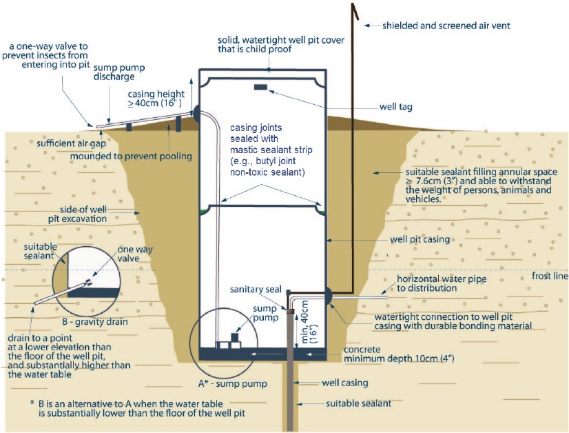
The figure is a cross-sectional view of a well inside of a concrete well pit. There are two major components to the figure; the well and its components, and the well pit and related components.
The drilled well is located at the bottom right of the well pit and below the frost line. As a minimum, the top forty centimetre portion of the well casing is exposed within the well pit, while the rest of the casing is below the bottom of the well pit. The annular space of the drilled well below the well pit is sealed with a suitable sealant.
The top of the drilled well has a sanitary seal from which two pipes extend vertically; a water pipe and an air vent. Both water pipe and air vent bend ninety degrees to the right, slightly above the well casing, and exit the well pit below the frost line. The water pipe and air vent exit the pit through a watertight connection to the well pit casing with durable bonding material. The water pipe is illustrated as remaining horizontal and extending to a distribution system. The air vent has another ninety degree bend and extends vertically through the well pit casing sealant to above ground surface. The top of the air is screened and shielded.
The well pit consists of two concrete tiles with a concrete base with a minimum thickness of ten centimetres (four inches) and a solid, watertight and child proof well pit cover. The lower concrete tile is shown completely below ground surface. The upper concrete tile is on top of the lower tile, and it is noted that the joint between the tiles is sealed with mastic sealant strip (e.g., butyl joint non-toxic sealant). About one-third of the upper concrete tile is above ground surface. The ground surface is highest around the well, with ground surface sloping away from the well. It is noted that mounding around the well is to prevent pooling of water around the well. It is further noted that the casing height above ground surface must be at least forty centimetres (sixteen inches). The well pit is constructed in an excavation which is filled with a suitable sealant and is able to withstand the weight of persons, animals, and vehicles.
On the bottom left side of the well pit, there is a water draining device (sump pump) shown. There are two options for drainage, which are detailed in Exploded Views A and B.
Exploded View A illustrates a sump pump at the bottom of the well pit. The sump pump has a discharge line that extends vertically to above ground surface, where the line bends to the left and exits the concrete tile through a watertight connection to the well pit casing. The discharge line is slightly raised above ground surface to provide a sufficient air gap, and has a one-way valve at the end to prevent insects from entering the pit.
Exploded View B illustrates a gravity drain at the bottom of the well pit. The drain has a one way valve inside the well pit. The drain exits the well pit through a watertight connection, with the drain pointing to a point at a lower elevation than the floor of the well pit. There is a note that states “B is an alternative to A when the water table is substantially lower than the floor of the well pit.”
At the bottom of the figure is the following caption: Sometimes the pump and air tank are located within the well pit.
Reminder: Larger diameter well pits are considered confined spaces. Persons working on well pits must only enter them when adequate safety precautions are followed based on Confined Spaces Regulation 632/05 under the Occupational Health and Safety Act are taken.
Reminder: This figure is not to scale, is for illustrative purposes for this chapter only and does not necessarily represent full compliance with other requirements found in the Wells Regulation.
Footnotes
- footnote[1] Back to paragraph ASTM International, West Conshohocken, PA.
- footnote[2] Back to paragraph Nielsen, David M. 2006. Practical Handbook for Environmental Site Characterization and Ground-Water Monitoring: Second Edition. CRC/Taylor and Francis. Boca Raton, Florida. Pp. 960-962.
- footnote[3] Back to paragraph Nielsen, David M. 2006. Practical Handbook for Environmental Site Characterization and Ground-Water Monitoring: Second Edition. CRC/Taylor and Francis. Boca Raton, Florida. Pp. 959-1102.
- footnote[4] Back to paragraph Adapted from Nielsen, David M. 2006. Practical Handbook for Environmental Site Characterization and Ground-Water Monitoring: Second Edition. CRC/Taylor and Francis. Boca Raton, Florida Chapter 15, P 997.
- footnote[5] Back to paragraph Nielsen, David M. 2006. Practical Handbook for Environmental Site Characterization and Ground-Water Monitoring: Second Edition. CRC/Taylor and Francis. Boca Raton, Florida. P 983.
- footnote[6] Back to paragraph ASTM Standard D6634 – 01(2006). "Standard Guide for the Selection of Purging and Sampling Devices for Ground-Water Monitoring Wells". ASTM International, West Conshohocken, PA, 2006. DOI: 10.1520/D6634-01R06.
- footnote[7] Back to paragraph Nielsen, David M. 2006. Practical Handbook for Environmental Site Characterization and Ground-Water Monitoring: Second Edition. CRC/Taylor and Francis. Boca Raton, Florida.
- footnote[8] Back to paragraph ASTM Standard D6634 – 01(2006). "Standard Guide for the Selection of Purging and Sampling Devices for Ground-Water Monitoring Wells". ASTM International, West Conshohocken, PA, 2006. DOI: 10.1520/D6634-01R06.
- footnote[9] Back to paragraph Nielsen, David M. 2006. Practical Handbook for Environmental Site Characterization and Ground-Water Monitoring: Second Edition. CRC/Taylor and Francis. Boca Raton, Florida. P1242.
- footnote[10] Back to paragraph Barbara B. Kebbekus, Somenath Mitra. Environmental Chemical Analysis. P129
- footnote[11] Back to paragraph Nielsen, David M. 2006. Practical Handbook for Environmental Site Characterization and Ground-Water Monitoring: Second Edition. CRC/Taylor and Francis. Boca Raton, Florida. Page 1241
- footnote[12] Back to paragraph Nielsen, David M. 2006. Practical Handbook for Environmental Site Characterization and Ground-Water Monitoring: Second Edition. CRC/Taylor and Francis. Boca Raton, Florida. Page 1242
- footnote[13] Back to paragraph Nielsen, David M. 2006. Practical Handbook for Environmental Site Characterization and Ground-Water Monitoring: Second Edition. CRC/Taylor and Francis. Boca Raton, Florida. P1010
- footnote[14] Back to paragraph Nielsen, David M. 2006. Practical Handbook for Environmental Site Characterization and Ground-Water Monitoring: Second Edition. CRC/Taylor and Francis. Boca Raton, Florida. P822
- footnote[15] Back to paragraph Eon-Products Inc.
- footnote[16] Back to paragraph Nielsen, David M. 2006. Practical Handbook for Environmental Site Characterization and Ground-Water Monitoring: Second Edition. CRC/Taylor and Francis. Boca Raton, Florida. P821
- footnote[17] Back to paragraph Hydrasleeve. GeoInsight, U.S. Patents No. 6,481,300; No. 6,837,120; others pending.
- footnote[18] Back to paragraph Snap Sampler
- footnote[19] Back to paragraph Nielsen, David M. 2006. Practical Handbook for Environmental Site Characterization and Ground-Water Monitoring: Second Edition. CRC/Taylor and Francis. Boca Raton, Florida. Pp1021-1025
- footnote[20] Back to paragraph Nielsen, David M. 2006. Practical Handbook for Environmental Site Characterization and Ground-Water Monitoring: Second Edition. CRC/Taylor and Francis. Boca Raton, Florida. Pp103 – 1032
- footnote[21] Back to paragraph Nielsen, David M. 2006. Practical Handbook for Environmental Site Characterization and Ground-Water Monitoring: Second Edition. CRC/Taylor and Francis. Boca Raton, Florida. Pp1016 – 1017
- footnote[22] Back to paragraph Nielsen, David M. 2006. Practical Handbook for Environmental Site Characterization and Ground-Water Monitoring: Second Edition. CRC/Taylor and Francis. Boca Raton, Florida. Pp1025 – 1027
- footnote[23] Back to paragraph Nielsen, David M. 2006. Practical Handbook for Environmental Site Characterization and Ground-Water Monitoring: Second Edition. CRC/Taylor and Francis. Boca Raton, Florida. Pp1031 – 1032
- footnote[24] Back to paragraph It should be noted that this photograph depicts a partially disassembled pump, which could not generate flow in that condition.
- footnote[25] Back to paragraph Powers, J. Patrick, Arthur B. Corwin, Paul C. Schmall, and Walter E. Kaeck. 2007. Construction Dewatering and Groundwater Control – New Methods and Applications; Third Edition. John Wiley & Sons, Inc., Hoboken, New Jersey.
- footnote[26] Back to paragraph Nielsen, David M. 2006. Practical Handbook for Environmental Site Characterization and Ground-Water Monitoring: Second Edition. CRC/Taylor and Francis. Boca Raton, Florida
- footnote[27] Back to paragraph Sterrett, Robert J. 2007. Groundwater and Wells: Third Edition. Johnson Screens/a Weatherford Company, St. Paul Minnesota
- footnote[28] Back to paragraph Nielsen, David M. 2006. Practical Handbook for Environmental Site Characterization and Ground-Water Monitoring: Second Edition. CRC/Taylor and Francis, Boca Raton, Florida. P893.
- footnote[29] Back to paragraph Photograph supplied by Global Water Instrumentation - a Xylem brand
- footnote[30] Back to paragraph Fleming College. 2010. Course Manual for Groundwater Monitoring Applications.
- footnote[31] Back to paragraph Sterrett, Robert J. 2007. Groundwater and Wells: Third Edition. Johnson Screens/a Weatherford Company, St. Paul Minnesota. Page 193, and Appendix 6F.
- footnote[32] Back to paragraph Investigation Report 98-4252 USGS Training Class SW4230
- footnote[33] Back to paragraph Photograph supplied by Global Water Instrumentation - a Xylem brand
- footnote[34] Back to paragraph Fleming College. 2009. Course Manual for Groundwater Monitoring Applications – Training for Ontario Class 5 License Applicants.
- footnote[35] Back to paragraph Photo courtesy of Fairbanks Morse, Pentair Flow Technologies
- footnote[36] Back to paragraph WSC PAS-97(04) – "WSC Performance Standards And Recommended Installation Procedures for Sanitary Water Well Pitless Adapters, Pitless Units, and Well Caps," Water System Council, Washington DC.
- footnote[37] Back to paragraph Nielsen, David M. 2006. Practical Handbook for Environmental Site Characterization and Ground-Water Monitoring: Second Edition. CRC/Taylor and Francis. Boca Raton, Florida. Pp.784-786.
- footnote[38] Back to paragraph Nielsen, David M. 2006. Practical Handbook for Environmental Site Characterization and Ground-Water Monitoring: Second Edition. CRC/Taylor and Francis. Boca Raton, Florida. P.787.