17. Abandonment: How to Plug & Seal Test Holes & Dewatering Wells
Chapter Description
This chapter covers the step-by-step process involved in abandoning a test hole or dewatering well as required by the Wells Regulation. This chapter outlines the sequential approach and materials used to plug and seal a test hole or dewatering well. The requirements listed in this chapter do not apply to shallow works or other exempted wells discussed in Chapter 3: Exemptions: Wells, Activities & Experienced Professionals.
Regulatory Requirements - Abandonment: How To Plug And Seal Wells
Relevant Sections - The Wells Regulation
Abandonment – Subsection 21(13) and Section 21.1 (How to abandon a well)
The Requirements - Plainly Stated
The Person Abandoning the Well
In the case of a well that must be immediately abandoned, the person abandoning the well is one of the following:
- the person who has discontinued the construction of a new well prior to the completion of its structural stage
- the well purchaser of a new well that is dry
- the well owner of a well that:
- is not in use or being maintained for future use as a well,
- is producing water that is mineralized or not potable (not applicable to test holes or dewatering wells),
- contains natural gas or other gas,
- permits the movement of materials including natural gas and contaminants and the movement may impair the quality of the waters, or
- is constructed in contravention of the Wells Regulation requirements for location, methods, materials or standards and measures taken to rectify the problem have failed.
Abandonment of a well is not considered well construction. As a result, licensing requirements for the construction of a well do not apply to well abandonment and the obligations for abandonment are placed on the person abandoning the well, often the well owner.
Obligation to Retain a Licensed Well Contractor
Unless exempted by the Wells Regulation, the person abandoning the well, often the well owner, must do the following:
- retain the services of a licensed well contractor, and
- ensure the contract with the well contractor contains a provision that the well technician who will do the abandonment work, is licensed to construct the same type of well as the one to be abandoned.
Exemption - Obligation to Retain a Licensed Well Contractor
The person abandoning the well is exempt from the above requirements if the person who works at the abandonment of the well is:
- the owner of the land or is a member of the owner’s household,
- working without remuneration (e.g., not being paid) for another person on land owned by the other person or on land owned by a member of the other person’s household, or
- a person who holds a Class 1 well technician licence (drilling).
How To Abandon A Test Hole or Dewatering Well
The person abandoning the well must ensure the following nine (9) steps are taken in this sequence, unless otherwise specified:
- If the well has a well tag, it must be removed and returned to the Director within 30 days of its removal.
- If the well casing or well screen has collapsed, reasonable efforts must be made to remove the well screen or well casing. All other equipment and debris in the well must be removed.
- The well, including any annular space, must be plugged in the following manner:
For Any Well:
Abandonment barrier material must be placed continuously from the bottom of the well upward to approximately 2 m (6.6ft) below the ground surface. This does not prevent the placement of clean, washed sand or gravel adjacent to water producing zones or bedrock fractures to minimize the loss of abandonment barrier (sealant) material.
The abandonment barrier must be placed in a manner that prevents any movement of water, natural gas, contaminants or other material between subsurface formations (which include aquifers) or between a subsurface formation and the top of the abandonment barrier material.
Alternative Method For Wells with a Diameter > 65.0 centimetres (> 2.1 ft):
A continuous column of abandonment barrier must be placed up to approximately 2 metres (6.6ft) below the ground surface as follows:
- Clean sand or pea gravel must be placed from the bottom of the well to the top of the deepest water producing zone or the top of the well screen, whichever is deeper
- At least 0.1 m (4 inches) of bentonite chips or pellets must be placed over the sand or pea gravel
- If the water level is below, or can be drawn down to the top of the bentonite chips or pellets:
- it must be drawn down to the top of the bentonite chips or pellets,
- at least 0.3 m (1 ft) of a bentonite slurry that consists of clean water and at least 20% bentonite solids and that is compatible with the quality of the water found in the well must be placed over the bentonite chips or pellets, and
- clean gravel, sand, silt or clay must be dropped over the bentonite slurry to fill the remainder of the well, while maintaining at least 0.3 m of the bentonite slurry above the rising accumulation of gravel, sand, silt or clay.
- If the water level cannot be drawn down to the top of the bentonite chips or pellets, the remainder of the well must be filled to approximately 2 metres (6.6ft) below the ground surface with an abandonment barrier, which may be interspersed (layered) with clean sand or pea gravel placed in each water producing zone of the well.
The sealing materials that are selected and placed must provide the appropriate structural strength to support the weight of persons and vehicles that may move over the area after it is filled.
- After or during the placement of the abandonment barrier, the well casing or well screen must be removed, if reasonably possible. During the removal of the well screen or well casing, the bottom of the casing must be immersed in the rising accumulation of the abandonment barrier material until the required level has been reached.
- If all of the casing and well screen cannot be reasonably removed as above, then at least 2 metres (6.6ft) of casing below the ground surface must be removed if reasonably possible
- If the abandonment barrier contains cement, it must set until firm and, if necessary, it must be topped up to approximately 2 m (6.6ft) below the ground surface.
- At any time before sealing the well to the ground surface (step 8), any below ground concrete structures, foundations, and slabs must be removed unless the removal may cause the remaining structures to become destabilized, damaged or unsafe. The structures have to be removed to a depth adequate to accommodate the sealing measures described below in step 8.
- To prevent inadvertent or unauthorized access, the well and the well opening (including any excavation) must be sealed up to the ground surface by placing:
- 50 cm (20 inches) to 150 cm (59 inches) of bentonite chips, pellets, granules or powder in accordance with the manufacturer’s specifications; and
- soil cover, or other material that is more in keeping with the material immediately adjacent to the well opening, over the bentonite and up to the ground surface to prevent inadvertent and unauthorized access.
- The disturbed area must be stabilized to prevent erosion.
Abandonment Barrier
Abandonment Barrier - General
The abandonment barrier must:
- be compatible with the quality of the water found in the well,
- not contain any materials that may impair the integrity of the abandonment barrier, including soil or drill cuttings, and
- be stable in the presence of any contaminants, if the well is in contact with contaminants
Abandonment Barrier - Wells ≤ 6.5 cm (2.5 inches) in Diameter
If the well casing and well screen have been removed or are being removed, the abandonment barrier must be a slurry consisting of:
- clean water, Portland cement and not more than 5% bentonite solids by weight, or
- clean water and at least 20% bentonite solids by weight, and the abandonment barrier must be placed using a tremie pipe, with the bottom of the tremie pipe immersed in the rising accumulation of the abandonment barrier until the required level has been reached.
The above also applies, with necessary modifications, to an uncased well that is less than or equal to 6.5 cm (2.5 inches) in diameter.
If the well casing and well screen have not been removed, the abandonment barrier must be:
- a slurry consisting of clean water, Portland cement and not more than 5% bentonite solids by weight, or
- bentonite chips or pellets that have been screened and placed in accordance with the manufacturer’s specifications.
Abandonment Barrier - Wells > 6.5 cm (2.5 inches) in Diameter
The abandonment barrier must be:
- a slurry consisting of clean water and at least 20% bentonite solids by weight,
- a slurry consisting of clean water, Portland cement and not more than 5% bentonite,
- a slurry consisting of clean water and Portland cement,
- a slurry consisting of clean water, Portland cement and clean sand,
- a slurry consisting of equal weights of Portland cement and clean gravel, mixed with clean water,
- a slurry (sometimes called a concrete slurry) consisting of clean water, Portland cement, clean sand and clean gravel,
- bentonite chips or pellets that have been screened and placed in accordance with the manufacturer’s specifications, or
- other material approved in writing by the Director, if the Director is of the opinion that the performance of the other material is the equivalent of the performance of a slurry referred to above.
A wet abandonment barrier for a well that has a diameter of greater than 6.5 cm (2.5 inches) must be placed using a tremie pipe, with the bottom of the tremie pipe immersed in the rising accumulation of the abandonment barrier until the required level has been reached.
Alternative Abandonment Barrier - Wells > 65 centimetres (2.1 ft) in Diameter:
See the alternate abandonment barrier material and method previously described in step 3 of “How to Abandon a Test Hole or Dewatering Well” in the Plainly Stated section of this chapter.
Abandonment of Flowing Wells:
If the well is a flowing well, commercially manufactured drilling mud that does not impair the quality of the water with which it comes in contact may be used, in taking the steps required above to assist with drilling or placement of an abandonment barrier, but the drilling mud may not be used as an abandonment barrier.
Well Pits:
A well pit must be abandoned like a well, with necessary modifications.
Overdrilling
Requirements for the removal of well casing and well screen in sequence (i.e., steps 2, 4 and 5 above) do not apply if a person overdrills (reams) the entire well before filling the well with abandonment barrier.
Reminder: If the entire well is over drilled, the entire well including the casing and well screen will be removed, allowing for the proper placement of the abandonment barrier.
Excavation of Entire Well
Except for step 1 (referring to well tags) the above plugging and sealing requirements do not apply when a person abandons a well by excavation of the entire well in the course of work carried out for another purpose (e.g., construction of a foundation).
Reminder: A person can abandon a well before it is completely excavated. In this case, the person abandoning the well, often the well owner, must ensure that:
- the “Obligation to Retain a Licensed Well Contractor” or the “Exemption - Obligation to Retain a Licensed Well Contractor” sections in Chapter 3: Well Contractors & Well Technicians – Licences, Responsibilities & Exemptions are followed,
- the well is abandoned following the nine sequential step approach described in this chapter, and
- unless exempt, a well record is completed and submitted as described in Chapter 13: Well Records, Documentation, Reporting & Tagging
Reminder: For further information on circumstances where excavating an entire test hole or dewatering well may be appropriate, see the “Excavating the Entire Test Hole or Dewatering Well” section in this chapter.
Reminder: The abandonment requirements found in this chapter do not apply to wells that meet the definition of “shallow works” or other wells exempted by the Wells Regulation. The abandonment requirements for “shallow works” are found in Chapter 3: Exemptions: Wells, Activities & Experienced Professionals.
Reminder: Unless exempt, the abandonment requirements found in this chapter apply to a test hole or dewatering well that is abandoned within 30 days of completion of its structural stage. A well record is not required to be completed for these test holes and dewatering wells. For further information and best management practices on well records see Chapter 15: Well Records, Documentation, Reporting & Tagging.
Reminder: Section 68 of the Nutrient Management General regulation (O. Reg. 267/03 as amended made under the Nutrient Management Act) requires that the qualified professional supervising the construction or expansion of a permanent nutrient storage facility shall ensure that the test holes that are excavated in the course of the site characterization and that are not required for any further purpose after site characterization, are plugged and sealed to provide a level of hydraulic conductivity that is the same or less than the hydraulic conductivity of the surrounding undisturbed soil.
Relevant Sections - Additional Regulations Or Legislation
Ontario Regulations 164/99: Electrical Safety Code as amended made under the Electricity Act, 1998. S.O. 1998. Chapter 15, Schedule A
Ontario Regulation 632/05: Confined Spaces as amended made under the Occupational Health and Safety Act, R.S.O. 1990, Chapter 0.1
Ontario Regulation 267/03: General as amended made under the Environmental Protection Act, R.S.O. 1990, Chapter E. 19
Relevant Standards
ASTM D5299-99(2005) – “Standard Guide for Decommissioning of Ground Water Wells, Vadose Zone Monitoring Devices, Boreholes and Other Devices for Environmental Activities.” (DOI: 10.1520/D5299-99R05 ). ASTM International, West Conshohocken, PA.
Relevant Guidance Documents
Fleming College. 2008. Manual for Continuing Education Course Safety for Ontario Well Technicians.
Key Concepts
The well abandonment process can vary depending on multiple factors including the diameter of a well, the well casing, the environment, and the condition of the well.
Initial Considerations
Prior to plugging a well, a person should review background records, including well records and hydrogeological reports, and conduct a site assessment.
Another initial factor to consider is who will be plugging and sealing the well. Regardless of who abandons the well, the requirements of the Wells Regulation must always be met.
Common Types Of Test Holes and Dewatering Wells Encountered
This chapter discusses well abandonment as it applies to:
- Narrow diameter wells less than or equal to 6.5 cm (2.5 inches), typically diamond drilled or point wells
- Medium diameter wells greater than 6.5 cm (2.5 inches) and less than or equal to 65 cm (2.1ft) typically drilled wells
- Large diameter wells over 65 cm (2.1ft), typically dug or bored wells
| Characteristic | Narrow Diameter Wells | Medium Diameter Wells | Large Diameter Wells |
|---|---|---|---|
| Hole Diameter (includes casing plus filled annular space) |
|
|
|
| Depth |
|
|
|
| Well Screen |
|
|
|
| Casing Material |
|
|
|
| Construction Method |
|
|
|
| Annular Seal where test hole or dewatering well is cased |
|
|
|
Reminder: Table 17-1 does not represent all possible situations due to changing technology, variation in construction techniques and changes in regulatory requirements.
Reminder: Well pits including utility structures, housing narrow and medium diameter wells are discussed further in this chapter.
Photographs Of Common Test Holes and Dewatering Wells
Figure 17-1 to Figure 17-10 are examples of the types of common test holes and dewatering wells that may be encountered in the field. The wells in the figures may or may not be in compliance with the Wells Regulation.
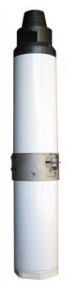
Figure 17-1: Typical Narrow Diameter Test Hole
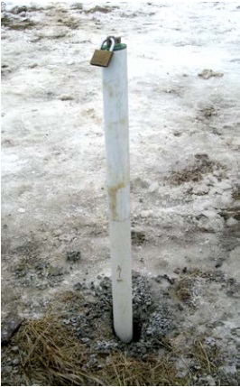
Figure 17-1 shows a narrow diameter white plastic casing of a test hole extending out of the ground. The top of the casing is sealed with an expandable plastic cap and lock. The annular space beside the casing has not been filled. The annular space can allow for surface water and other foreign materials to move from the ground surface to the aquifer and impair the groundwater.
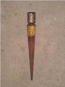
Figure 17-2: Point Well

Figure 17-2 shows the components of a well constructed with the use of a driven point. The components have been removed from an abandoned test hole and are temporarily laying on the ground surface. The steel point is located in the lower left portion of the photograph. The steel well screen is attached to the point. A coupling is located in about the middle of the photograph. The coupling joins them well screen with the steel riser pipe (casing).
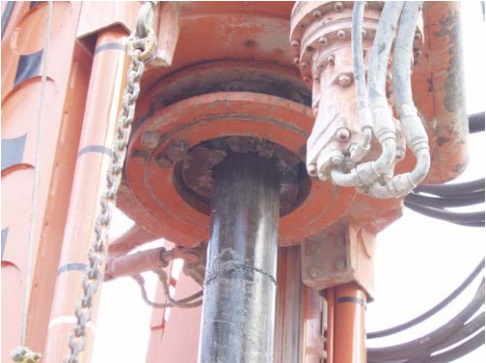
Figure 17-3: Typical Medium Diameter Test Hole
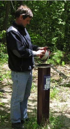
Figure 17-3 shows a medium diameter black steel casing extending out of the ground. The hinged vermin-proof well cap is open. The person is about to install a water level meter into the well to obtain a groundwater level measurement.
Figure 17-4: Group of Monitoring Wells
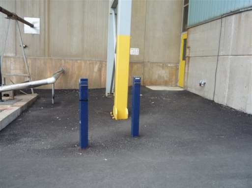
Figure 17-4 shows two monitoring wells (test holes) located within a small area. Each test hole is within a blue protective steel well cover with a hinged locking top. Each test hole is completed at a different depth to monitor specific zones in the aquifer. This is commonly known as a cluster or group of wells.
Figure 17-5: Group of Monitoring Wells
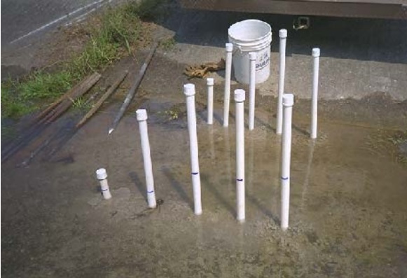
Figure 17-5 shows two rows of monitoring wells (test holes). The test holes have well screens at different depths. The blue marks on the well casings indicate the groundwater levels above the ground surface in the test holes. Given the amount of water around the wells, it appears groundwater is discharging along the annular space of one or more of the wells to the ground surface. This is causing a flooding problem and is a waste of the groundwater resource. It may also be allowing contaminants to reach other groundwater zones or the ground surface.
Figure 17-6: Drilled Well in a Well Pit
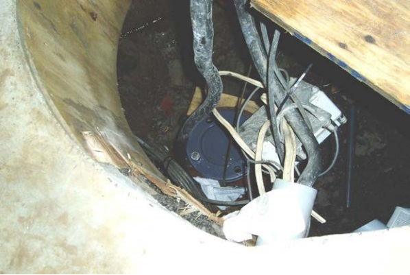
Figure 17-6 shows an example of an improperly abandoned drilled test hole. The test hole was originally used to monitor water levels during the pumping of a nearby municipal well. The abandoned test hole is located inside a well pit. The well pit is located inside a municipal pump house. Further information on this test hole is found in Figure 16-1 (Improperly Abandoned Test Hole) of Chapter 16: Abandonment: When to Plug & Seal Test Holes & Dewatering Wells.
Figure 17-7: Drilled Well in Flush-Mounted Well Pit (Vault)
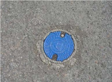
Figure 17-7 shows an example of a test hole installed in a flush-mounted well pit (vault). A flush-mounted well pit (vault) is typically installed when a test hole is constructed in an area subject to pedestrian or vehicular traffic. It is designed to contain the upper portion of the test hole, prevent the upper portion of the well and waterlines from freezing, and allow access to the top of the well. In this case, the vault is covered with a blue manufactured flushmounted well pit (vault) cover.
Figure 17-8: Typical Point System for Dewatering
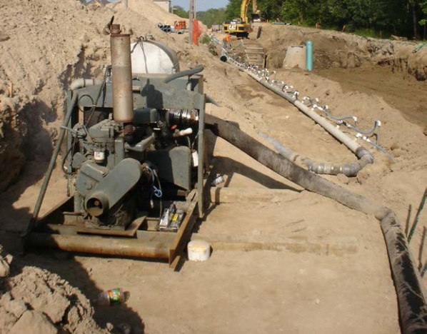
Figure 17-8 shows a large diesel operated pump on the left side of the photograph. A white large diameter horizontal header (suction line) is attached to the suction side of the pump. The top of the point wells are attached to the header in the upper right portion of the photograph. The black large diameter hose from the pump is the discharge pipe in the lower right hand portion of the photograph. The dewatering point system is being used to lower the groundwater level to facilitate installation of underground utilities.
Figure 17-9: Typical Educator Well System for Dewatering
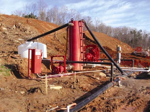
Figure 17-9 shows an eductor well casing extending out of the ground immediately in front of two large black horizontal header lines. One horizontal header is a high pressure supply line. The other horizontal header is a low pressure return line. Orange waterlines connect the supply and return headers to the top of the well. Waterlines also connect the supply and return headers to a central pump station (red tower, red pumps and white priming tank). The eductor system allows for wells to dewater at a greater depth than a typical suction lift system shown in Figure 17-8.
Figure 17-10: Typical Deep Well System for Dewatering
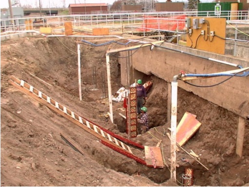
Figure 17-10 shows a construction site with an excavation. Three wells, as represented by the white casings extending out of the ground, are shown in the excavation. Waterlines and electrical cables extend through the top of each well. The waterlines and electrical cables are attached to deep well submersible pumps. The three discharge lines are connected to a common header carrying the discharge water towards the upper left portion of the diagram. The system is designed to lower the groundwater level at a deep depth.
Types Of Filling Materials And Abandonment Barriers
It is necessary to use plugging materials that will ensure proper sealing of the well. The choice of plugging materials is important to:
- ensure the abandoned well does not act as preferential pathway for water, gas or foreign materials between:
- groundwater zones,
- between groundwater and the ground surface,
- provide the best overall strength to the abandoned well to support the weight of persons, animals and vehicles,
- provide sufficient viscosity to minimize leakage of the plugging material out of the well and into the groundwater resource or formation, and
- provide the best adhesion of the plugging material to the casing, soil or bedrock to achieve a good seal.
The type of materials selected will depend on the:
- location (e.g., hazards, access restrictions),
- environment (e.g., flowing conditions, presence or absence of contaminants or natural gases, chemistry of the water),
- type of well,
- diameter and depth of the well,
- condition of the well (e.g., damage to the well structure, collapsed casing equipment/debris caught in the well), and
- requirements of the Wells Regulation
There are a variety of materials used to plug a well. Plugging materials are made up of:
- abandonment barriers (e.g., concretem grout, neat cement and sodium bentonite) to prevent the creation of preferential pathways,
- filling materials which include:
- clean, washed sand or gravel placed in large voids, fracture areas or adjacent to water producing zones to:
- support abandonment barrier,
- prevent leakage of the abandonment barrier into the groundwater resource or formation, and
- restore subsurface conditions at the well site, and
- clean gravel, sand, silt or clay placed in large diameter wells [> 65 cm (2.1ft)] to reduce the quantity of abandonment barrier required to seal the well and to provide increased bearing strength.
- clean, washed sand or gravel placed in large voids, fracture areas or adjacent to water producing zones to:
Field Notes And Well Records
During the process of well abandonment, the person abandoning a well is required to make and have available at the well site field notes that include an up-to-date record of the abandonment activities.
A well record documenting the abandonment of the well must be completed by the person abandoning the well, often the well owner, and submitted to the owner of the land on which the well is located and the Ministry (see Chapter 15: Well Records, Documentation, Reporting & Tagging).
How To Abandon Test Holes and Dewatering Wells
The steps involved in the abandonment of a test hole or dewatering well are as follows:
Initial Procedures
- Obtaining and Reviewing Relevant Records and Conducting a Site Assessment
- Determining Expertise Required
- Selecting Plugging Materials
- Estimating Plugging Material Volumes Required
- Preparing Equipment, Selecting Methods and Obtaining Approvals Needed to Plug the Well
- Determining if Overdrilling is a Best Management Practice
Nine Sequential Step Procedures To Plug And Seal A Well
- Safeguarding and Returning the Well Tag
- Removing Equipment, Structures, Debris and Any Collapsed or Broken Well Casing or Well Screen
- Plugging and Sealing Within 2 Metres (6.6 Feet) of the Ground Surface
- Removing Entire Casing and Well Screen During Sealing
- Removing Casing
- Using Cement or Concrete
- Removing Below Ground Concrete Structures and Slabs
- Plugging and Sealing of Upper 2 Metres (6.6 Feet) of the Well Opening
- Stabilizing Disturbed Area
After The Well Is Plugged And Sealed
- Completing and Submitting a Well Record
- Providing Important Information to the Well Owner
Initial Procedures
1) Obtaining And Reviewing Relevant Records And Conducting A Site Assessment
Persons plugging a test hole or dewatering well can use the well record information along with a site assessment of the well to determine the method and materials needed before commencing to plug and seal a well.
To obtain relevant information on the test hole or dewatering well to be abandoned, a person should consider if there are any historical records of the well.
For example, a well contractor may have completed a well record and log for the original construction of the well. A copy of the original well record may be available from the:
- current or previous land owner,
- original well contractor, or
- Ministry of the Environment and Climate Change.
Well records provide valuable information including the:
- depth and diameter(s) of the well,
- overburden and bedrock encountered during construction,
- depth where groundwater was found,
- depth to static water level in the well,
- general water quality information (e.g., salty, sulphurous),
- presence of naturally occurring gases (e.g., methane, hydrogen sulphide),
- construction materials used in the well (e.g., casing, screen), and
- general location of the well (e.g., UTM, co-ordinates, township or municipality information, map).
In some cases original well records may not be available for the test hole or dewatering wells. For example, some test holes or dewatering wells that have a life span of less than 30 days may not have a well record filed with the Ministry or the well owner.
Another example of relevant source of information is hydrogeological reports. Hydrogeological reports can be prepared as a result of various activities including:
- phase 2 environmental site assessments,
- work related to the delineation clean-up, monitoring and clean-up of contaminants, and
- hydrogeological investigations for water supplies.
The reports may provide technical information and mapped locations of test holes or dewatering wells. These reports may be found at the local:
- Ministry of the Environment and Climate Change office
- Municipality
- Conservation authority
Best Management Practice – Assessing the Well
An assessment of a test hole or dewatering well should be conducted prior to plugging and sealing it. The assessment should include the following factors: the well depth, the water level, the geochemistry of the well water, the pumping or other equipment in or around the well, the structure of the well and the geological formations around the well. The use of video technology by trained professionals should be included in deep wells to visually confirm the well’s characteristics and current conditions.
Reminder: There are many serious dangers that must be considered when assessing and working on abandoned wells. Some dangers include the following:
- When inspecting a well, the power supply to the pump or any monitoring equipment should be shut off to minimize the risk of shock or electrocution.
- Many older wells especially dug wells have structural integrity problems and could collapse. Some test holes or dewatering wells constructed without casing may also pose similar problems. As such, it is important to wear appropriate safety gear and to guard against falling into the well. Falling into the well could result in serious injury or death.
- An abandoned well could contain contamination or explosive or poisonous gases that could affect a person’s health and safety. As such, it is important to use proper field detection equipment and personal protective gear.
Reminder: It is important that no person enter any confined space unless the person is properly trained in confined space entry and is properly equipped. Confined spaces are non-ventilated areas including a well pit, a pump house, and other areas defined in the Ontario Regulation 632/05 as amended made under the Occupational Health and Safety Act
Reminder: For further information on conducting a site assessment when abandoning a test hole or dewatering well see the “Initial Project Considerations” section of Chapter 5: Siting Considerations & Initial Planning.
Visual Assessments
Figure 17-11: Video Technology Used Within A Drilled Well
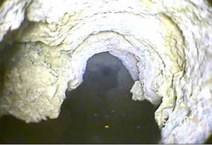
Figure 17-11 shows a still shot from a video of the open hole portion of a drilled well in bedrock. The hole has a large crevice, which could not be observed from land surface. With this video information, the well contractor can more accurately calculate the amount of plugging material needed and select the best method and equipment to seal the hole.
Figure 17-12: Video Camera And Cable
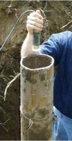
In Figure 17-12 the video camera and cable are about to be installed in an drilled well.
Figure 17-13: Video Displaying A Well’s Interior
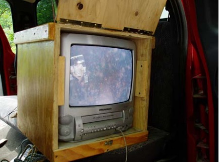
In Figure 17-13 the orange and white (mottled) areas shown on the video display indicate that the well water has a significant organic biofilm problem. Therefore, the well will need to be cleaned out and treated prior to plugging to reduce the chance of microorganisms moving from the well and impairing the groundwater resource.
Figure 17-14: Encrusted Metal Screen
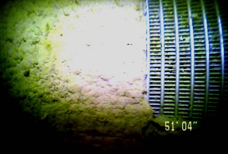
Figure 17-14 shows another example of a video display of a well’s interior. In this example, the stainless steel well screen at the bottom of a well is plugged with a biofilm. The person who works at the abandonment of the well needs to remove the screen to ensure the filling material will properly allow for the return of the natural groundwater flow at the well site and the biofilm will not react with the filling materials or abandonment barrier.
Best Management Practice – Conducting On-site or Laboratory Testing and Analysis of Well Water
It is important to conduct on-site or laboratory testing and analysis of the well water to further understand the hydrogeological environment around the well and to determine if the well water may react with the plugging materials or abandonment barriers. See Table 17-3 in this chapter for a description of abandonment barriers. A Professional Engineer or Professional Geoscientist may be needed to interpret the laboratory or field results.
2) Determining Expertise Required
Another initial factor to consider is who will be abandoning (plugging and sealing) the test hole or dewatering well. Regardless of who abandons the well, the requirements of the Wells Regulation must always be met.
If a well owner is a corporation or municipality, the well owner must retain the services of a licensed well contractor who employs properly licensed well technicians to work on the well abandonment unless exempt. In some cases the corporation or municipality can use a person who holds a Class 1 well technician (drilling) licence to abandon a test hole or dewatering well. Also, the corporation or municipality can use a person described in the list below to abandon the test hole or dewatering well if the person uses non-powered equipment in the abandonment operation:
- a licensed Professional Engineer including a person holding a limited or temporary licence,
- a Professional Geoscientist who is a practicing, temporary or limited member or
- a professional registered as a certified technician, certified engineering technician, applied science technologist or certified engineering technologist (CET) with the Ontario Association of Certified Engineering Technicians and Technologists.
An individual land owner or his/her family members can abandon any well situated on his/her own property without a well technician licence. Also, other individuals can abandon a well without a well technician licence for the individual land owner as long as no form of compensation is made.
Although the Ontario Water Resources Act and the Wells Regulation allow an individual well owner to abandon his/her own well without a licence, the equipment, materials and expertise needed to comply with the requirements under the Wells Regulation can exceed the average land owner’s abilities and resources. A well owner needs to understand how to measure water levels, well depths and be able to calculate volumes of well water, chemical mixtures and material mixtures. For instance, if an individual land owner cannot properly calculate and mix chemicals, does not have the necessary equipment, or cannot employ proper safety procedures, the requirements of the Wells Regulation will not likely be met. An improperly abandoned well could pose a safety or environmental hazard and the well owner may be subject to compliance or enforcement actions.
For further information, licensing requirements are detailed in Chapter 4: Well Contractors & Well Technicians – Licences, Responsibilities & Exemptions. Contact numbers for the Ministry are also listed in the Resources section of this manual.
Best Management Practice – Retaining Licensed Well Contractor and, if Necessary, Qualified Persons
Because of the need for specialized equipment and technical skill, which may be beyond the capabilities of an individual well owner, it is important that wells with one or more complicating factors be plugged by a licensed well contractor who employs licensed well technicians. It may also be advisable that Professional Geoscientists or Professional Engineers be retained. Complicating factors include:
- Test holes or dewatering wells with well water that may be impacted by on or off-site contaminants (e.g., gasoline, fuel oil, pesticides or agricultural activities)
- Test holes near municipal well fields
- Freely flowing artesian test holes or dewatering wells where groundwater is discharging from the well at or close to ground surface
- Flowing, heaving and/or running formations (e.g., sands or gravels) are encountered
- Underground crevices in karstic formations
- Test holes or dewatering wells greater than 9 metres (30 feet) deep
- Test holes or dewatering wells where surface water runoff, insects or other vermin are entering the well through the well casing
- Test holes or dewatering wells which produce poisonous or explosive gas, salty water or sulphate-rich water
- Test holes or dewatering wells where the casing has collapsed or the casing is difficult or not reasonably possible to remove without proper equipment
- Areas with difficult access or access requiring specialized equipment
- Unusually heavy components associated with the test hole or dewatering well
- Nested test holes with multiple casings and layers of bentonite and filter pack materials (i.e., nested multiple test hole with seals)
- Test holes or dewatering wells where the pumping equipment is difficult or not reasonably possible to remove
- Test holes or dewatering wells located in residential, agricultural, commercial or industrial buildings (occupied or vacant)
- Test holes or dewatering wells located in close proximity to other wells in operation
- Test holes or dewatering wells located in close proximity to surface water
- Improperly abandoned wells (e.g., plugged with logs or other materials)
Reminder: There may be additional conditions, other than the above list, that make it advisable for the test hole or dewatering well be plugged and sealed by licensed professionals.
In some cases, driven and shallow dug test holes or dewatering wells can be plugged by land owners with a minimal amount of special equipment. However, land owners who improperly abandon (plug and seal) wells may face enforcement actions and additional legal liabilities (e.g., property and environmental damage, personal injury). Re-drilling, re-excavating, and having to plug and seal the well a second time creates a significant increase in costs that could have been avoided if the original plugging and sealing was properly completed.
3) Selecting Plugging Materials
A) Filling Materials
Clean, washed sand or gravel is placed in large voids, bedrock fracture areas or adjacent to water producing zones to:
- support the abandonment barrier,
- prevent leakage of the abandonment barrier into the groundwater resource or formation, and
- restore natural groundwater flow at the well site.
Clean gravel, sand, silt or clay is placed in large diameter wells [> 65 cm (2.1ft)] to reduce the quantity of abandonment barrier required to seal the well and to provide increased load bearing strength.
- Clean
- with respect to gravel, sand, silt or clay, means that it should at least:
- be washed with clean water to remove finer textured material in the case of gravel or coarse sand, and
- not cause an impairment of the well water.
| Material | Particle Diameter | Characteristics |
|---|---|---|
| Clay | < 0.002 mm |
|
| Silt | 0.002 – 0.05 mm |
|
| Sand | 0.05 – 2.0 mm (0.002 – 0.08 inch) |
|
| Gravel | 2.0 – 75.0 mm (0.08 – 3.0 inches) |
|
These filling materials are mined at local pits and quarries and either sold at the pit or quarry or at building and material supply stores.
Best Management Practice – Use Table 1 in Soil, Groundwater and Sediment Standards to Meet Parameter Concentrations in Filling Materials
To ensure gravel, sand, silt or clay placed in an abandoned well is clean, the person who works at the abandonment of the well should consider having all gravel, sand, silt or clay meet the parameter concentrations of Table 1 in Soil, Groundwater and Sediment Standards for Use under Part XV.1 of the Environmental Protection Act April 15, 2011. The table is located on the Ontario website.
It is up to the person abandoning the well to ensure that the filling materials are clean prior to their installation into the well.
B) Abandonment Barriers
The Wells Regulation - Depending on the diameter of the well, the abandonment barrier can be a slurry consisting of:
- clean water and at least 20% bentonite solids by weight,
- clean water, Portland cement and not more than 5% bentonite,
- clean water and Portland cement,
- clean water, Portland cement and clean sand,
- equal weights of Portland cement and clean gravel, mixed with clean water, or
- clean water, Portland cement, clean sand and clean gravel (sometimes called a concrete slurry).
The Wells Regulation - The abandonment barrier can also be either:
- bentonite chips or pellets that have been screened and placed in accordance with the manufacturer’s specifications, or
- other material approved in writing by the Director, if the Director is of the opinion that the performance of the other material is the equivalent of the performance of a slurry referred to above.
Reminder: For further information on the type of abandonment barrier to be used in a well see the abandonment barrier information presented in the “Plainly Stated” section and the “step 3: Plugging and Sealing To Within 2 Metres (6.6 Feet) of the Ground Surface” section in this chapter.
Cement
Neat cement is a mixture of one 43 kilogram (94 pound) bag of Portland cement (Type I or IA) to not more than 19.7 litres (4.3 Imperial gallons) of clean water. The person adding the water needs to ensure all lumps of solids are removed in the mixture. Adding more than 19.7 litres (4.3 Imperial gallons) of water per bag will create a thinner mixture. Thinner mixtures will have reduced strength and may cause shrinkage and open crack issues. Portland cement is readily available at building supply stores. Other grades of Portland cement used in the industry are American Petroleum Institute (API) cements classified as B, C, G, H, K, M and S which may be used depending on the sulphate concentrations or when there is a need for retarders/retardants or accelerators with the cement. Further information on cement can be found at the following website titled Cement and Concrete Basics.
Concrete
Concrete grout is a mixture of neat cement (see above) with a specific quantity of sand and/or gravel. Concrete is readily available or can be made on-site by mixing one 43-kilogram (94-pound) bag of Portland cement with 0.03 cubic metres (1 cubic foot) of sand or gravel and not more than 19.7 litres (4.3 Imperial gallons) of water.
Reminder: See the “Mixing Cement or Concrete Grout (Sealant)” section in Chapter 7: Annular Space & Sealing, for further information on mixing cement and concrete with water.
Bentonite
Sodium bentonite is a manufactured product that is made from volcanic deposits of sodium montmorillonite clays. The product comes in a powder form for mixing with water. The product also comes in chip, pellet and granular forms that may be added directly into the well water or that may be hydrated prior to adding to the well. When water is properly mixed with the sodium bentonite, the mixture should look like oatmeal porridge. When it hydrates (sets) it should resemble peanut butter. A proper mixture of 20% solids by weight should be a mixture of 91 L (20 Imp gal) of clean water to 23 kgs (50 lbs) of dry sodium bentonite powder. The mixture will generate a material volume of about 100 L (or 22 Imp gal).
Reminder: See the “Mixing Cement or Concrete Grout (Sealant)” section in Chapter 7: Annular Space & Sealing, for further information on mixing cement and concrete with water.
Sodium Bentonite with Cement
In some cases 3 % to 5 % bentonite by weight is used as an additive to cement or concrete to improve the workability (make it more fluid), weight and density of the cement slurry. Bentonite is chemically incompatible with cement and will not swell significantly in a cement slurry. The bentonite additive also reduces the set strength of the seal, lengthens set time, increases shrinkage and open cracking. For these reasons, bentonite must not exceed 5% of the mixture by weight.
Table 17-3 in this chapter provides some general information on advantages and disadvantages of cement and bentonite based abandonment barriers.
| Abandonment Barrier | Advantages | Disadvantages |
|---|---|---|
| Bentonite Based Abandonment Barriers |
|
|
| Cement Based Abandonment Barriers |
|
|
C) When Contaminants Or Naturally Occuring Mineralized Water Are Present
The Wells Regulation - In choosing an abandonment barrier, the material must:
- be compatible with the quality of the water found in the well. In some cases, sulphate rich waters will react and destabilize Type I Portland cement. In some salt rich waters or DNAPL conditions, sodium bentonite will not set properly and destabilize.
- not contain any materials (e.g., retardants or accelerators) that may impair the integrity of the abandonment barrier, including soil or drill cuttings.
- be stable in the presence of any contaminants. If contaminants such as gasoline, fuel oil or nutrients are present in the groundwater or formation, the person abandoning the well will need to ensure that a proper plugging material is chosen. Unstable materials may not properly set and may affect the integrity of the structure.
Reminder: When in doubt, a small sample batch of the intended abandonment barrier should be mixed and placed in container with a sample of the well water. Any reactions should be observed.
D) Alternate Abandonment Barrier Products (Director’s Written Approval)
The Wells Regulation allows for the use of seven types of abandonment barrier materials which are described in section 3) B) of this chapter. In some cases, approved abandonment barrier materials may not be suitable for the environment or available for the plugging and sealing operation, therefore, other materials may be used if written consent is provided by the Director.
Prior to well abandonment, the person abandoning the well, often the well owner, may apply and seek the written consent of the Director to use a type of abandonment barrier material other than the seven abandonment barriers in section 3) B) of this chapter as long as the performance of the material is at least equivalent to the performance of the listed abandonment barriers.
How Can the Person Abandoning a Well Request and Obtain a Written Consent From the Director?
The person abandoning a well, often the well owner, may contact the Wells Help Desk:
- in writing to Wells Help Desk, Ministry of the Environment and Climate Change, 125 Resources Road, Toronto, ON M9P 3V6,
- by fax at:
416-235-5960 , or - by e-mail at helpdesk@waterwellontario.ca.
For further information, the well owner can contact the Wells Help Desk by telephone at
The person abandoning a well, often the well owner, should provide a written request with the following information:
- the name of the individual(s)/entity that owns the well,
- the location of the well,
- an indication as to whether or not the well in question is new or an existing well,
- the purpose and use of the well,
- the reason for the alternate abandonment barrier request (e.g., contaminant(s) of concern encountered or trying to stop a flowing well), and
- if applicable, written certification for the use of an alternate barrier material by the manufacturer or a Professional Engineer.
The person abandoning a well may be required to retain a Professional Engineer or Professional Geoscientist who would have to prepare a scientific report showing the appropriate scientific rationale to support the application. The person abandoning a well would have to submit the report along with the request for written consent to the Ministry for its consideration.
Depending on the case, and as part of the Director’s consideration, the Director may ask other regulators and interested parties to comment on the application.
How Does the Director’s Decision Process Work?
The request for written consent must be submitted to the Director along with any and all supporting documents such as a hydrogeological, well plugging design and/or abandonment barrier design report(s). The person abandoning the well and others should be aware that obtaining a written consent will not be an automatic process. The Ministry has to provide for the conservation, protection and management of Ontario’s waters and for their efficient and sustainable use, to promote Ontario’s long-term environmental, social and economic well-being.
The Director will review the request, supporting information and other information generated from internal and external parties with an interest in the application. Based on the review, the Ministry will contact the person abandoning the well, in writing, indicating the Director’s decision
4) Estimating Plugging Material Volumes Required
Table 17-4 may be useful to estimate how much cement, concrete or sodium bentonite plugging material is needed to plug a well. Further calculations are provided in “Calculating Amount of Materials Required” section of Chapter 7: Annular Space and Sealing, Calculating Amount of Material Required section.
When plugging wells into bedrock or gravel deposits, large open fractures or open void spaces around the well can cause material to leak out of the well and into the formation. This and other hole irregularities (e.g., Figure 17-11) can increase the volume of plugging material required. Extra material should be available in the event there is an underestimation.
| Well Diameter Centimetres |
Well Diameter Inches |
Metres (Feet) of Well Plugged Using One Bag of Neat Cement 43 kg (94 lbs) bag |
Metres (Feet) of Well Plugged Using One Bag of Concrete 43 kg (94 lbs) bag |
Metres (Feet) of Well Plugged Using One Bag of Sodium Bentonite 23 kg (50 lbs) bag |
|---|---|---|---|---|
| 3 | 1 ¼ | 42 m (138 ft) | 76 m (250 ft) | 126 m (413 ft) |
| 6 | 2 ¼ | 13 m (43 ft) | 24 m (77 ft) | 39 m (127 ft) |
| 8 | 3 ¼ | 6 m (20 ft) | 11 m (37 ft) | 19 m (61 ft) |
| 11 | 4 ¼ | 4 m (12 ft) | 7 m (22 ft) | 11 m (36 ft) |
| 13 | 5 ¼ | 2 m (8 ft) | 4 m (14 ft) | 7 m (23 ft) |
| 16 | 6 ¼ | 1.7 m (6 ft) | 3 m (10 ft) | 5 m (17 ft) |
| 21 | 8 ¼ | 1 m (3 ft) | 1.7 m (6 ft) | 2.9 m (9 ft) |
| 26 | 10 ¼ | 0.6 m (2 ft) | 1.1 m (4 ft) | 1.9 m (6 ft) |
| 31 | 12 ¼ | 0.4 m (1.4 ft) | 0.8 m (2.6 ft) | 1.3 m (4.3 ft) |
| 61 | 24 | 0.11 m (0.4 ft) | 0.21 m (0.7 ft) | 0.34 m (1.1 ft) |
| 91 | 36 | 0.05 m (0.2 ft) | 0.09 m (0.3 ft) | 0.15 m (0.5 ft) |
Reminder: The formula in this table is based on the industry standard well casing diameter in inches for drilled wells and some dug wells. The calculated numbers have then been rounded
5) Preparing Equipment, Selecting Methods And Obtaining Approvals Required To Plug The Well
Prior to plugging the well, the following should be determined:
- The type of heavy equipment needed to remove structures, casings, screens and well equipment. This could include a drilling rig, excavator (backhoe or high hoe), water trucks, cement trucks, gravel trucks, cement pumping trucks, stake trucks containing extra casing, welding materials, and other tools.
- The location of nearby pits and quarries that supply filling materials such as gravel. The location of retailers of cement or bentonite will also be important in choosing the materials and methods to plug the well.
- A source of high quality clean water for preparing a slurry.
- The type of specialized equipment such as fishing tools or casing cutters to remove collapsed casing, obstructions or equipment stuck in the well.
- The type and method of installing the plugging materials in the well such as tremie pipes, attachments to casings and grout pumps.
- The location for disposing of any contaminated materials that are removed at the well site.
- Appropriate health and safety precautions. See the Safety Manual for Well Technicians
footnote 5 and the Ministry of Labour’s website for additional information. - Any approvals, permits or other instruments that may be necessary before the operation commences. For example:
- If groundwater is anticipated to discharge from a well before abandonment, or is discharging from a well during abandonment, at a volume of more than 50,000 litres (11,000 imperial gallons) on any one day, a Permit To Take Water under the Ontario Water Resources Act must be required. More information on Permit To Take Water approvals can be found on the Ontario website.
- The person abandoning the well must ensure that the groundwater, debris and other materials discharging from the well do not cause adverse environmental impacts such as erosion, impairment of surface water courses and/or off-site flooding. This may require the use of settling pits on the property. A sewage works environmental compliance approval under the Ontario Water Resources Act may be required if the person abandoning the well discharges the water, drill cuttings or other material and the discharge capacity exceeds 10,000 litres per day. A guide to explain the sewage works process can be found on the Ontario website.
6) Determining If Overdrilling Is A Best Management Practice
In some cases plugging a well without removing the casing and well screen may not effectively seal the well to prevent the vertical movement of surface water, contaminants and other foreign materials. Some examples include:
- An annular space (open space beside the casing) may exist below the ground surface in some test holes or dewatering wells. The open space can act as a pathway for contaminants to move between formations.
- The casings of a multi-level monitoring well may be adjacent to one another and the space between them may not be properly sealed. The space between the casings can act as a pathway for contaminants.
- Multi-level monitoring wells using dedicated systems may need to have all casing lengths and ports removed to properly fill the entire well with abandonment barrier.
In these situations, a person abandoning a well could consider overdrilling the test hole or dewatering well (see Best Management Practice titled “Overdrilling the Test Hole or Dewatering Well” in this section).
Best Management Practice – Overdrilling the Test Hole or Dewatering Well
Overdrilling should be used in situations where the casing or well screen cannot reasonably be removed, and where leaving them in the well may inhibit the formation of an effective seal that prevents the vertical movement of surface water, contaminants and other foreign materials.
The overdrilling method involves using a rotary drilling machine with a specialized drill bit that is larger than the filled annular space of the well. The specialized drill bit can cut casing and well screen that is made out of steel or plastic. In certain overburden deposits, hollow-stem auger flights can be used to overdrill around the casing.
The casing, well screen and other material in the well and the well’s annular space are removed by the drilling operation. The open hole is held open by temporary casing. In some cases, bedrock, till and clay formations, may have sufficient strength to prevent well collapse and would not require the use of a temporary casing. The open hole can then be filled with the appropriate abandonment barrier material and other filling material using the nine step sequential method (see the “Nine Sequential Step Procedure to Plug and Seal a Well” section in this chapter).
The method offers assurance that the entire hole is filled with abandonment barrier or other filling materials to reduce the risk of the well acting as a pathway for contaminants.
Figure 17-15 to Figure 17-20 show aspects of the overdrilling process of well abandonment.
Reminder: If the test hole or dewatering well has a well tag, the well tag must be removed prior to overdrilling the well (see the “Nine Sequential Step Procedure to Plug and Seal a Well” section in this chapter).
Figure 17-15: Abandoned Nested Multi-Level Monitoring Well
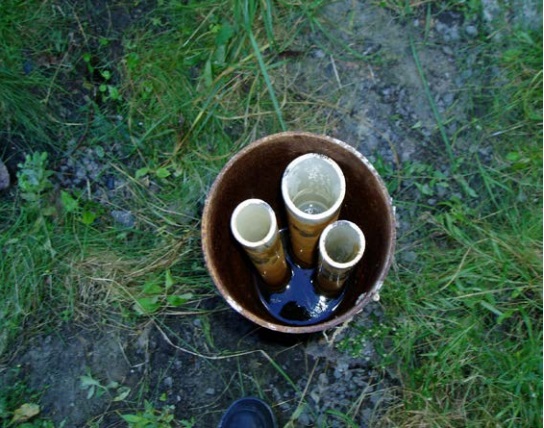
Figure 17-15 shows three white PVC plastic casings surrounded by groundwater within the permanent steel outer casing. The plastic casings extend to well screens located at different intervals in the test hole. Sealant has not been properly placed between the well screens or at the top of the well and groundwater has moved to near the top of the well. Groundwater and potential contaminants from the different zones in the bedrock can intermingle which may impair waters and cause a bias in sample results. To properly seal the hole, the white casings, well screens and gravel in the well need to be removed before abandonment barrier is placed in the well.
Figure 17-16: Overdrilling Abandoned Nested Multi-Level Monitoring Well
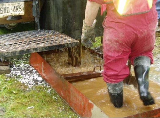
Figure 17-16 shows a driller using a rotary drill rig to initially overdrill the interior of the well shown in Figure 17-15. The bit and rods are drilling inside the well casing and open hole of the well. The upper portion of the well casing is located immediately left the technicians hand. The equipment is drilling through brown water, gravel and plastic. Compressed air from the drill rig is being forced down the well causing the brown water, gravel and plastic to come to the surface.
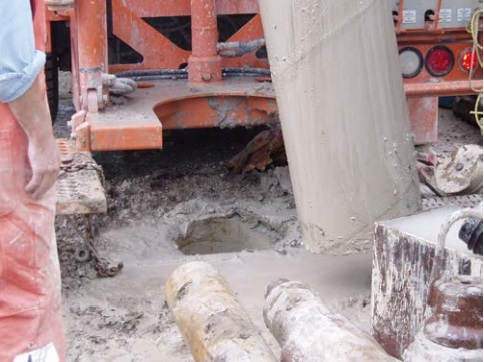
Figure 17-17: Material Obtained From Overdrilling Abandoned Nested Multi-Level Monitoring Well
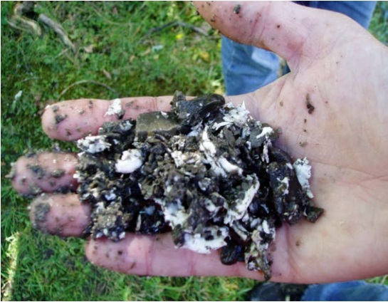
Figure 17-17 shows a closer view of the gravel and broken white plastic casing being drilled out from the well shown in Figure 17-15. A suitable sealant such as bentonite was not observed during the removal process. The lack of suitable sealant confirms the need to properly abandon the well using overdrilling to eliminate the pathway for groundwater and potential contaminant migration.
Figure 17-18: Inner Casings Removed Prior to Complete Overdrilling
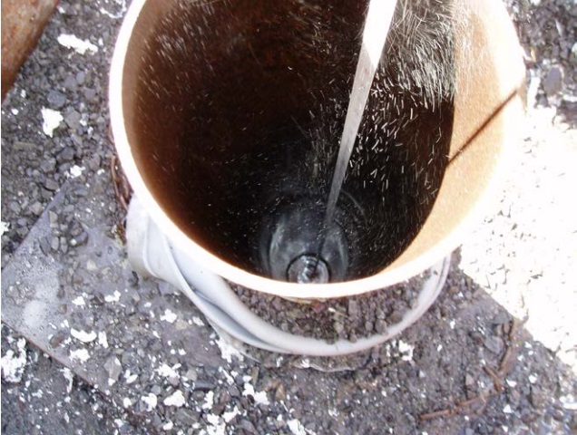
Figure 17-18 shows the interior of the well shown in Figure 17-15 completely reamed out. The well has also been pumped to remove the brown water. The permanent outer casing and annular seal around this casing must also be overdrilled prior to filling the well with plugging and sealing materials.
Figure 17-19: Overdrilling Around a Casing
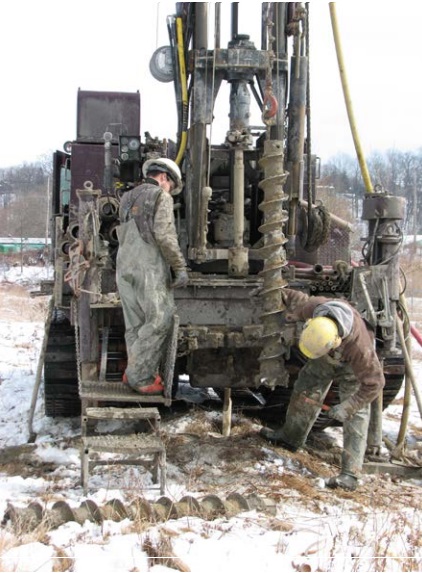
Figure 17-19 shows licensed well technicians using a track mounted drill/auger rig. The technicians are using a cable on the rig to move a hollow-stem auger flight. The flight will be attached to the top head drive on the drilling mast. Prior to augering, a steel riser pipe was installed into the 2 inch white plastic well casing and pushed into the well screen. The well is about to be overdrilled with the hollow-stem auger flights. The overdrilling procedure will take place around the existing casing removing any open voids or permeable material placed in the original annular space.
Figure 17-20: Overdrilling Around a Casing
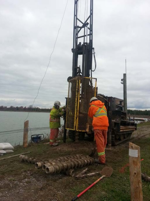
Figure 17-20 shows licensed well technicians using an overdrilling method around the well casing similar to what is shown in Figure 17-19. In this case, the top head drive of the track mounted drill/auger rig is rotating and pushing a hollowstem auger flight into a clay overburden deposit and around a casing.
Nine Sequential Step Procedure To Plug And Seal A Well
The person abandoning the well, often the well owner, must ensure the following nine steps are taken in sequence unless otherwise specified.
Best Management Practice – Working Efficiently and Covering the Abandoned Well
For safety reasons and to prevent the well acting as a pathway for contaminants, the person abandoning the well should ensure the person working on the well:
- manages equipment, time and resources to complete the plugging and sealing steps in one day or less, and
- covers the well in a manner that prevents the entry of surface water and other foreign materials if the person working on the abandoned well leaves the site before completing the plugging and sealing steps.
1) Safeguarding And Returning The Well Tag
The Wells Regulation - If the well has a well tag, it must be removed and returned to the Director within 30 days after its removal.
Since August 2003, persons constructing wells have been required to affix Ministry issued well tags onto many new and altered test holes and dewatering wells.
If the well has a well tag attached to the well casing or near the well, the well tag must be removed at the beginning of the plugging operation and safeguarded throughout the process.
The well tag must be returned within 30 days after completion of abandonment and removing the tag. The well tag must be returned to Wells Help Desk, Ministry of the Environment and Climate Change, 125 Resources Road, Toronto, Ontario, M9P 3V6 (
Best Management Practice – Using Unique Field Numbers for Untagged Existing Wells in a Well Cluster
If a well tag is affixed to the deepest test hole or dewatering well in a well cluster, no other well in the cluster is required to be tagged. If a well with a well tag is abandoned, the well tag must be returned to the Director. If the deepest well is abandoned, but other untagged wells in the well cluster remain, the person abandoning the well should physically label each remaining well in the well cluster with a unique field number. The person could use the entry on the “Well Number on Drawing” field from the original Well Record form for the “Well Cluster” as the unique field number for the well. Well tags cannot be used as the label for this purpose as well tags can only be used as prescribed under the Wells Regulation. The unique field numbers should be reported on the well record for the well abandonment to link the remaining wells in the field with the well record.
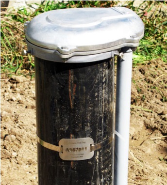
Figure 17-21: Well Tag On Drilled Well
2) Removing Equipment, Structures, Debris And Any Collapsed Well Casing And/Or Well Screen
2(A) Structures And Slabs
In some cases, wells are housed in pump houses or other structures to protect the well head from the winter environment or to house pumping and electrical equipment near the well. There are also cases where wells are housed in buildings. Removal of slabs and structures can be done at any time before step 8 [“Plugging and Sealing the Upper 2 Metres (6.6 Feet) of the Well Opening” section in this chapter] is undertaken.
Best Management Practice – Remove Pump House, Protective Cover or Concrete Slabs as Soon as Possible
If the well is located within a pump house, has a protective well cover or there are slabs of concrete surrounding the well casing at or near the ground surface, the pump house, protective well cover or the concrete slabs, should be removed to the extent practical, at the start of the abandonment of the well. Any barriers should also be removed to allow for abandonment equipment to access the well. The well should be properly covered to prevent the entry of surface water and other foreign materials during the removal process.
Reminder: In cases where wells are housed in residential dwellings or other buildings and the building will continued to be used, see step 7 “Removing Below Ground Concrete Structures and Slabs” on this chapter for additional details.
Figure 17-22: Dewatering Well in Above Ground Structure
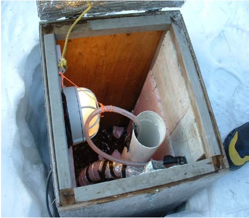
Figure 17-22 shows the top of a dewatering well’s white plastic casing located within a small wooden structure. The structure is heated and insulated to prevent freezing. A waterline is installed in the dewatering well. A proper cap or cover has not been placed on the well as required. All of the equipment must be removed before starting to plug the well with abandonment barrier and filling material.
Figure 17-23: Protective Cover and Barriers
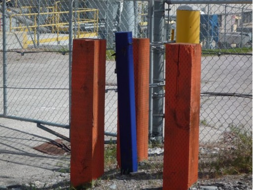
Figure 17-23 shows a blue protective cover housing a test hole. The protective cover is surrounded by three wooden posts. The posts act as a barrier to prevent vehicles from hitting the test hole. The wooden posts and protective cover should be removed to allow access for abandonment equipment to plug and seal the test hole.
Figure 17-24: Protective Cover Removal
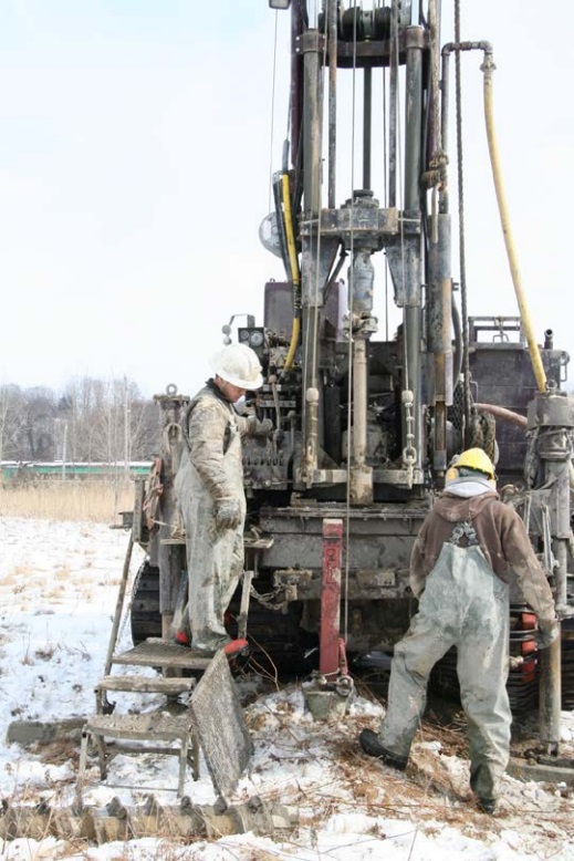
Figure 17-24 shows a track mounted drill/auger rig pulling a red protective cover from the ground. The concrete pad into which the bottom of the protective cover was set is also being removed at the same time.
Figure 17-25: Protective Cover Removal
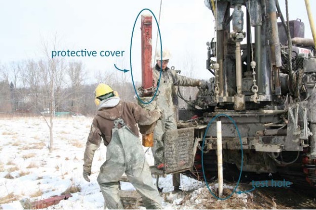
Figure 17-25 shows the same test hole as in Figure 17-24. In this photograph, the technicians have used the track mounted drill/auger rig to fully remove the red protective cover and concrete pad from the ground. The removal of the protective cover has exposed the top of the white plastic casing of the test hole.
Figure 17-26: Flush-Mounted Well Pit (Vault) with Concrete Pad
Figure 17-26 shows the top of three blue flushmounted well covers. Test holes are located below the well covers in flush-mounted well pits (vaults). As a concrete pad has been placed around each vault, depending on the abandonment process, part or all of the concrete pads may need to be removed to access the well and well pit (vault).
2(B) Equipment
The person abandoning the well must ensure the person working at the abandonment of the well removes all pumping equipment, waterlines (drop pipes), electrical equipment, connections, pipes, and other equipment from the well.
Figure 17-27: Electrical Cables
Figure 17-28: Electrical Cables - Close Up
Electrical cables going into a drilled well to a submersible pump, as shown in Figure 17-27 and Figure 17-28, are a safety hazard if they are damaged or not properly disconnected and removed.
Figure 17-29: Monitoring Well with Equipment
Figure 17-29 shows electrical connections to dedicated pressure transducers and other equipment in the well attached to a datalogger and telemetric equipment that is housed in a green box. The green box is attached to the top of the steel well casing. The equipment is used to measure water levels and various water quality parameters. All of the equipment down the well and attached to the top of the well will need to be removed before the well is plugged with abandonment barrier and filling material. The removal of the equipment will help ensure that the entire well is properly plugged.
Figure 17-30: Dewatering Well With Equipment
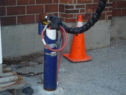
Figure 17-30 shows pumping equipment extending out of a dewatering well. Removal of all of the pumping equipment from the well is necessary prior to the installation of the abandonment barrier material into the well. The removal of the equipment will help ensure that the entire well is properly plugged
Figure 17-31: Drilled Well With Equipment
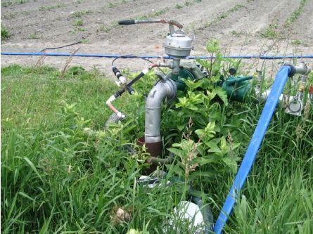
Figure 17-31 shows pumping equipment (drop pipe) extending out of the well without a watertight seal on the top of the casing. Removal of pumping equipment, including the drop pipe, from the drilled well is necessary prior to the installation of the abandonment barrier material. The removal of the equipment will help ensure that the entire well is properly plugged.
2(C) Collapsed Well Casing And Well Screen
Over time, steel well casing can corrode and plastic well casing can degrade or crack. Corrosion, degradation or cracks create openings and allow the migration of contaminants.
If possible, broken well casing or well screen should also be removed from the well. There are a variety of drilling tools that can be used to remove broken casing and well screen. For example a backhoe or highhoe can remove casing in overburden environments up to about 9 metres (30 feet) below the land surface.
Figure 17-32: Removal Of Well Casing
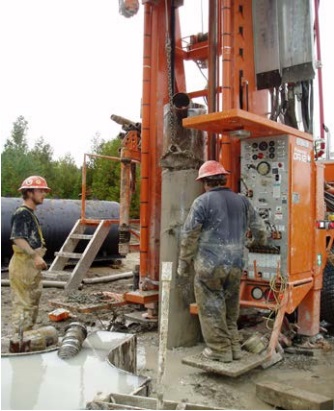
Figure 17-32 shows the removal of well casing using a drilling rig with a chain attached to the rig’s winch.
Figure 17-33: Removal Of Well Casing
The drilling rig raises the chain and casing out of the ground leaving the well open. The rig has removed the casing from the well.
Figure 17-34: Removal Of Well Casing
Another method of casing removal is to attach the upper portion of casing to a casing rotator. The casing is being raised up the drilling mast.
Figure 17-35: Tapered Tap
A tapered tap, such as the one shown in Figure 17-35, is used to spear the broken casing. The device is lowered from the drill rig. Once attached into the casing, the drill rig can raise the casing out of the well. Other similar attachments that can be used are a sandlock or trip spear.
Figure 17-36: PVC Casing Puller
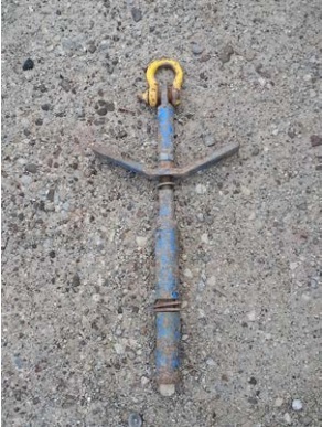
Figure 17-36 shows a plugging device. The device is affixed to the top of the casing. Using a cable that is attached from the drill rig’s mast to the plugging device, the rig can raise the casing out of the ground. See Figure 17-37.
Figure 17-37: Removal of Casing and Well Screen With Casing Puller
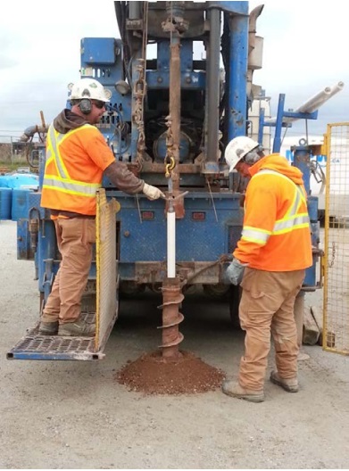
Figure 17-37 shows a PVC casing puller, shown in Figure 17-36, placed into the top of the white PVC casing. The casing puller is attached to cable on a track mounted rig. Using the plug and cable, workers lift the white casing and well screen (not shown) out of the ground. The removal of the casing occurs after an overdrilling process has been completed.
Figure 17-38: Riser Pipe
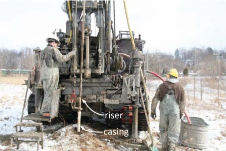
Figure 17-38 shows a steel riser pipe being placed into the white casing using a track mounted rig. Later in this process, clean sand will be installed between the casing and the riser pipe (not shown). The sand provides friction between the riser and casing and allows the rig to pull the riser with the casing and well screen out of the ground. The removal of the casing will occur after an overdrilling process has been completed (see Figure 17-19 and Figure 17-20).
Figure 17-39: Casing Cutter
The white casing cutter shown in Figure 17-39 is attached to drill rods on the drill rig. The cutter and drill rods are lowered into a cased well to the desired elevation by the drill rig and operator. The cutter and drill rods are rotated by the drill rig. During the rotation, the cutter (the grey steel in centre of the white cutter) will cut the well casing.
Cutting a length of casing and leaving some casing in the ground is allowed if it is not reasonably possible to remove the entire casing while sealing the well with abandonment barrier.
Figure 17-40: Casing Cutter
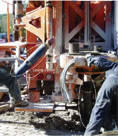
Figure 17-40 shows a blue casing cutter that has been removed from the top head drive of the drill rig. The casing cutter was originally attached to the bottom of drill rods and placed in the well using the drill rig. The casing cutter was used to cut the casing at the predetermined depth below the ground surface. The top of the casing is shown below the rotator table on the right side of the photograph. The rotator table will attach to the casing and pull the cut piece of casing out of the well.
Cutting a length of casing and leaving some casing in the ground is allowed if it is not reasonably possible to remove the entire casing while sealing the well with abandonment barrier.
Figure 17-41: Corroded Casing From Inside
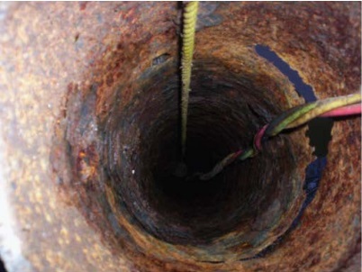
Figure 17-42: Corroded Casing From Outside
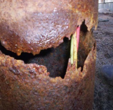
Figure 17-41 and Figure 17-42 show the interior and exterior of a drilled well with casing corroded to a point that a significant hole has formed through the well casing. The hole is seen on the right side of Figure 17-41 and can also be seen in Figure 17-42. The open hole acts as a pathway for surface water and other foreign materials to enter and contaminate the aquifer.
Reminder: During the removal process of large diameter concrete well casing, reasonable efforts must be made to remove any broken concrete tiles from the well before proceeding with further plugging and sealing steps.
Best Management Practice – Abandoning a Well with Collapsed Well Casing
When abandoning a well that has a collapsed well casing, the person abandoning the well should retain a Professional Engineer or Professional Geoscientist. The professional should assess the well. The casing and equipment should be removed by an experienced licensed well technician who holds a well contractor licence or who works for a licensed well contractor. A video camera assessment of the well can assist in the identification and location (depth) of problems in the casing, obstructions and equipment. Solutions may include using fishing tools, re-drilling, overdrilling or excavating the well.
Reminder: The person working on the abandonment can remove intact well casing before step 3 if the person working on the abandonment uses an overdrilling method to rip out the entire well including the casing. See the “Plainly Stated” section in this chapter and step 6 “Determining if Overdrilling is a Best Management Practice,” in this chapter for further information on overdrilling.
2(D) Obstructions
If obstructions are not removed from abandoned wells before plugging, the lower portion of the well below the obstruction will not be effectively plugged, resulting in an open conduit for contaminant migration.
Obstructions may include any of the following:
- Pumping equipment
- Devices to measure water levels, water quantity or well water quality such as flow meters, or pressure transducers
- Materials that have inadvertently or naturally entered the well
- Inflatable packers used to stop well water from discharging out of a flowing well
- Pitless adapters, grounding devices, well seals and caps
Figure 17-43: Drilled Well Partially Filled With Concrete
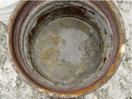
Figure 17-43 shows the view inside a drilled well that has only been partially filled with concrete. There is also an unsealed portion of the well below the concrete plug (not visible). The concrete needs to be carefully drilled out by an experienced well driller prior to properly plugging and sealing the well.
Figure 17-44: Pitless Adapter On Outside Of Casing
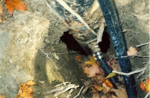
Figure 17-44 shows the outside of the well casing from ground level with a pitless adapter and horizontal waterline extending from the well. The pitless adapter needs to be removed from this well casing prior to plugging and sealing. Also, the photograph shows a large opening on the outside of the well that will need to be filled.
Figure 17-45: Pitless Adapter On Inside Of Casing
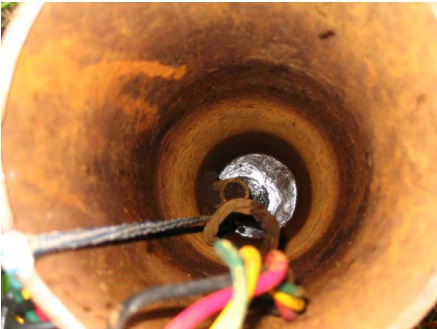
The pitless adapter shown in Figure 17-45, is located just above the well water level and extends through the left side of the drilled well casing. The pitless adapter needs to be removed along with the drop pipe, and the submersible pump’s three coloured electrical wires, the cable and rope.
2(E) Debris
All debris, including biofilm must be removed from the test hole or dewatering well to ensure that it will not interfere with the setting of the plugging material and not impair the groundwater.
Figure 17-46: Debris To Be Removed
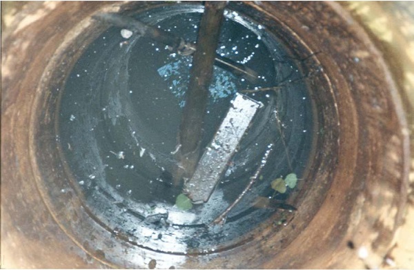
The debris shown in the dug well in Figure 17-46 consists of wood, pipe, sticks and leaves which may interfere with the plugging material’s (abandonment barrier’s) performance.
Examples Of Methods For Removing Debris And Biofilms
Submersible Pump Method
One method of removing debris involves the installation of a clean submersible pump and drop pipe in the well. The pump, wires and drop pipe should be soaked in a solution of fresh unscented bleach and clean water prior to installation.
Best Management Practice – Removing Volumes of Well Water Column
As part of the removal of debris and biofilm from the well, it is recommended that, where feasible, at least 20 volumes
The well water removal process will also remove some of the organic biofilm such as iron bacteria that may have built up on the sides of the well. Biofilm can spread through an aquifer to other wells and inhibit chlorination processes. See the “Other Chemical Treatment” section in Best Management Practice – Using Shock Chlorination Where Appropriate” in this chapter.
As an example, if a 16 cm (6 ¼ inches) diameter drilled well contained a column of 10 m (33ft) of water, the well would hold about 200 L (or 44 Imp gal) of water. Thus, at least 4,000 L (or 880 Imp gal) should be pumped from the well.
A pail and timer (e.g., an accurate watch or stop watch) can be used to measure the pumping rate. The pump should be kept at a constant rate using appropriate equipment such as a dole valve, globe valve or ball valve.
For example if a person needed to pump 4,000 L (880 Imp gal) of water and has a 20 L (4.4 Imp gal) pail, the person can observe the seconds it takes for the pumped well water to fill up the pail. If it takes 1 minute for the 20 L pail (4.4 Imp gal) to completely fill, then at least 200 minutes of pumping would be needed to remove 4,000 L (880 Imp gal) of water from the well.
Reminder: For information on proper handling of discharge water and relevant approvals see “Handling Discharge Water” section in Chapter 13: Water Level Measurements, Aquifer Testing & Discharge Water Handling. If approvals are necessary, it is important that they be obtained before starting to remove (pump) the well water.
Table 17-5 provides different well diameters and the estimated volume of water per metre (or foot) in the well. Multiplying the height of the water column by the estimated volume per metre (or foot) will provide the estimated volume of water in the well column.
| Well Casing Inner Diameter (Centimeters) |
Well Casing Inner Diameter (Inches) |
Volumes of Water (Litres per metre) |
Volumes of Water (Imperial Gallons per Foot) |
|---|---|---|---|
| 3 | 1 ¼ | 0.8 | 0.05 |
| 6 | 2 ¼ | 2.6 | 0.17 |
| 8 | 3 ¼ | 5.4 | 0.36 |
| 11 | 4 ¼ | 9.2 | 0.61 |
| 13 | 5 ¼ | 13.9 | 0.94 |
| 16 | 6 ¼ | 19.9 | 1.33 |
| 21 | 8 ¼ | 34.6 | 2.31 |
| 26 | 10 ¼ | 53.1 | 3.57 |
| 31 | 12 ¼ | 76.0 | 5.09 |
| 61 | 24 | 292.2 | 19.55 |
| 91 | 36 | 656.1 | 43.99 |
Reminder: The formula in this table is based on the industry standard well casing diameter in inches for drilled wells and some dug wells. The calculated numbers have then been rounded.
Figure 17-47: Pumping With A Submersible Pump
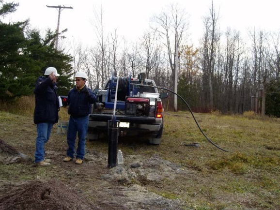
Figure 17-47 shows a submersible pump and waterline installed into the well. Using a generator on the back of the pickup truck as a power source for the pump, well water and debris are being pumped out of the well and discharged on the ground surface at a safe location.
Compressed Air Method
In some cases, drilling machines blowing air are used to remove water with the debris and a portion of biofilm from the well. See the above note on this section for information on where to find best management practices in this manual regarding the proper handling of discharge water.
Figure 17-48: Compressed Air Removal Of Debris
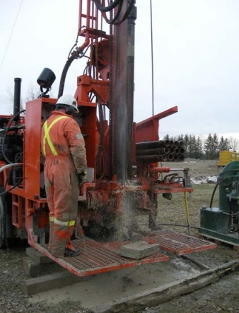
The person operating the rotary rig in Figure 17-48 is using a compressor to blow air under high pressure and a high rate through drill rods into the well. The air forces well water and debris up the well to the ground surface. In this case, the well water is not contaminated.
Best Management Practice – Using “Shock” Chlorination Where Appropriate
To ensure potential disease causing organisms in the well water or groundwater near the well do not move with groundwater flow to other area wells, well water should be “shock” chlorinated, where appropriate, prior to the plugging and sealing of a well (see Chapter 10: Test Hole & Dewatering Well Exemption and Activity: Disinfection for further information). If biofilm from organisms such as iron bacteria or sulphate reducing bacteria is present, mechanical and chemical cleaning are recommended prior to chlorinating the well.
However, “shock” chlorination is not appropriate for certain wells sites where free chlorine can create chlorinated contaminants (see If Chlorination of Well Water Presents a Hazard below).
Sodium hypochlorite (unscented bleach) is commonly used in the chlorination process. Bleaches are available at local grocery and hardware stores. Other products may be used to chlorinate water such as calcium hypochlorite and lithium hypochlorite. Commercial bleach at 12% available chlorine is also used by many well contractors. Correct calculations must be made when using this product to ensure proper concentrations in the well. Proper safety procedures need to be employed when handling sodium hypochlorite or the other oxidization agents since they are harmful to humans (see Chapter 10: Test Hole & Dewatering Well Exemption and Activity: Disinfection for further information).
Chlorinating the Well
“Shock” chlorination should target a free chlorine residual in the range of 50 to 200 milligrams per litre to remove pathogens from well water (see Chapter 10: Test Hole & Dewatering Well Exemption and Activity: Disinfection). To obtain the target concentration range in the well see the formulae, and tables in Chapter 10: Test Hole & Dewatering Well Exemption and Activity: Disinfection).
The formulae do not consider metals and organics that will consume the solution prior to creating the oxidizers in the water. As such, free chlorine residual test equipment should be used to verify a free chlorine residual in the well water. Common methods to measure the free chlorine residual such as a colour-wheel test kit and digital colorimeters are shown in Chapter 10: Test Hole & Dewatering Well Exemption and Activity: Disinfection.
Discharging Chlorinated Well Water
It is important, that at the end of treatment period the chlorinated well water be pumped from the well to a suitable storage tank, neutralized, and then discharged to a location that will not cause an adverse effect on the natural environment. It is also important that the chlorinated water from the well be pumped to ensure it does not move through the aquifer and impair nearby wells or surface water (see Chapter 10: Test Hole & Dewatering Well Exemption and Activity: Disinfection for further information).
If Chlorination of Well Water Presents a Hazard
Where the chlorinated water may cause an adverse health reaction or hazard when mixed with other chemicals present in the well water and groundwater, the well contractor and well owner should not chlorinate the well.
Some situations where well chlorination treatment should not occur may include groundwater contaminated with arsenic or with a high naturally occurring arsenic concentration. The addition of sodium hypochlorite may elevate arsenic in the groundwater near the well.
In other cases, a nearby well may be hydraulically connected to the well being chlorinated. The chlorinated water may move from the abandoned well to a nearby well and impair the quality of the well water. As such, chlorinating the well before plugging should either not occur or proceed with monitoring of the nearby well. A contingency plan that is ready to be activated to prevent any adverse effects should be in place.
Other Chemical Treatment
In some cases, acid blends using specific biodispersants or other chemical treatments are used to dislodge biofilm and other encrustations from the sides of the well. The biofilm may then be mechanically cleaned andremoved from the well by pumping or compressed air. Only qualified and licensed professionals should conduct these specialized methods and treatments (see Chapter 14: Test Hole & Dewatering Well Maintenance & Repair for additional information).
3) Plugging and Sealing to Within 2 Metres (6.6 Feet) of the Ground Surface
The Wells Regulation - The abandonment barrier must be placed in the test hole or dewatering well, including any annular space, in a manner described in this section until a depth of about 2 m (6.6ft) below the ground surface is reached.
This does not prevent the placement of clean, washed sand or gravel adjacent to water producing zones or bedrock fractures to minimize the loss of abandonment barrier (sealant) material.
The abandonment barrier must be placed in a manner that prevents any movement of water, natural gas, contaminants or other material between subsurface formations (which include aquifers) or between a subsurface formation and the top of the abandonment barrier material.
Reminder: See the “Determining if Overdrilling is a Best Management Practice” section in this chapter when determining if the annular seal, filter pack or other material beside the casing should also be sealed.
The Wells Regulation identifies different methods for placing plugging materials into test holes or dewatering wells depending on the diameter of the well.
3(A) Well Diameter Greater Than 6.5 cm (2.6 inches)
These medium and large diameter sized test holes or dewatering wells are typically drilled wells, but can also be constructed by direct push or auger methods. Larger diameter dug and augered wells can follow this option or the alternative option listed in Step 3 (C) in this chapter. See Table 17-1 for further information of small, medium and large diameter wells.
The abandonment barrier used to plug these test holes or dewatering wells can consist of neat cement, concrete and sodium bentonite slurries, sodium bentonite chips or pellets, mixtures of not more than 5% sodium bentonite with neat cement or a plugging material approved by the Director (See “Selection of Plugging Materials” section in this chapter).
Best Management Practice – Taking Precautions when Using Dry Bentonite Products
If sodium bentonite pellets or chips are used, the material needs to be screened and placed in accordance with the manufacturer’s specifications. Precautions when plugging a well with dry bentonite products include:
- ensuring sealing material does not bridge when placing material,
- pouring the products at a rate no faster than 3 minutes per 22 kilogram (50 lb) bag,
- using pellets or chips that are coated with a material that increases the length of time before bentonite starts to swell once it contacts water,
- halting the pouring process occasionally and lowering a weighted measuring tape into the well until it reaches the top of the products to confirm that bridging has not occurred,
- using a tamping device to break any bridges that form, and
- making sure bentonite is continually hydrated, where necessary, by periodically adding clean water to the bentonite that has been placed in the well.
If sand or gravel is used to fill the water producing zones or open fractures in bedrock, similar precautions to those used for sodium bentonite pellets or chips should be followed.
Figure 17-49: Bentonite Chips
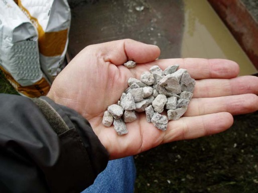
Figure 17-49 shows medium sized manufactured coated bentonite chips.
Figure 17-50: Pouring Bentonite Chips
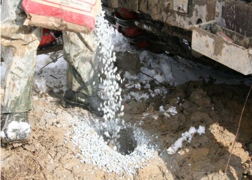
Figure 17-50 shows a licensed well technician pouring bentonite chips in an abandoned well. In this case the well casing and well screen were originally removed using an overdrilling technique. This hole remained open after casing removal and overdrilling because the overburden deposit has sufficient strength and stability to prevent formation collapse. In other cases, a temporary casing or auger flight may need to be installed to hold the hole open. Manufacturers have different specifications for screening and placement of bentonite chips or pellets; this figure shows one example.
Figure 17-51: Hydrating Bentonite Chips
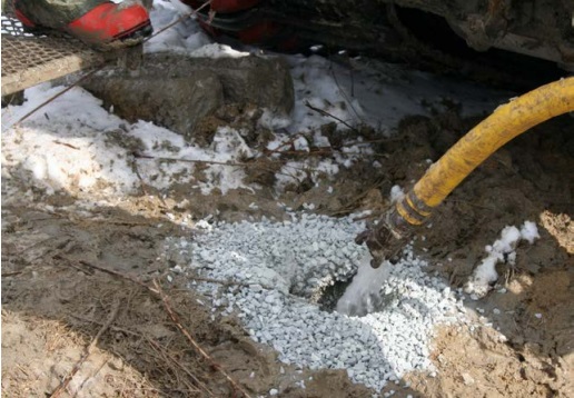
Figure 17-51 shows a licensed well technician periodically adding clean water to the hole shown in Figure 17-48. The addition of clean water allows the bentonite chips that have been placed into the hole to hydrate and form a seal in the well.
If a slurry abandonment barrier is used, the best abandonment barrier material that will properly plug and seal the test hole or dewatering well should be chosen (See the "Selecting of Plugging Materials" section in this chapter).
The Wells Regulation - Any wet abandonment barriers (i.e., slurries) must be placed in the test hole or dewatering well (including the annular space) from the bottom of the well using a tremie pipe with the bottom of the pipe immersed in the rising accumulation of the abandonment barrier.
Care is required to prevent the tremie pipe from becoming stuck in the abandonment barrier within the well. This will include raising the tremie pipe during the operation.
The tremie pipe typically extends from a grout mixing machine and pump at land surface to the bottom of the test hole or dewatering well, as shown in Figure 17-53. As an alternative, a pipe is sometimes attached from the grout mixing machine and pump to the top of the well casing. The casing is then used as the tremie pipe as shown in Figure 17-54.
If well water, and any other material displaced during this operation is contaminated (e.g., contains gasoline), the water must be collected and disposed of in an approved manner. No person shall discharge the contaminated water and waste material that causes or may cause an adverse effect to the natural environment.
The person abandoning the well will need to properly store or transport the contaminated water and waste material.
If a person wishes to haul contaminated water or waste material to a regulated waste disposal site, the person must have an approved waste management system (i.e., holds a valid certificate of approval) to carry the contaminated water or waste material, must meet the requirements of the General – Waste Management Regulation (Regulation 347 as amended made under the Environmental Protection Act) and must dispose of the contaminated water or waste material at a licensed facility that is listed on the certificate of approval. A guide to explain approved waste management systems can be found on the Ontario website.
If the displaced water is not contaminated, it should be directed away from the well site to minimize the likelihood of the water flowing into the well opening. For information on proper handling of discharge water and relevant approvals see the “Handling Discharge Water” section in Chapter 13: Water Level Measurements, Aquifer Testing and Discharge Water Handling.
Figure 17-52 to Figure 17-62 show some grout mixing equipment and methods of plugging and sealing test holes or dewatering wells.
Figure 17-52: Grout Mixing Machine
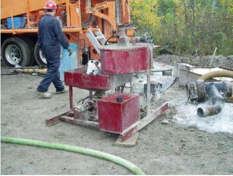
Figure 17-52 shows a grout mixing machine. Material is placed and mixed in an upper tray and then transferred to a lowered into a lower tray, where it is pumped through a tremie pipe (not shown) to the well behind the drilling rig. It is not recommended to use dual tank grout mixing units with bentonite based grout because separation of the product and water can occur when grout is not agitated in the pumping tank. This results in a flash setting of grout in the tremie line or non-uniform grout consistency.
Figure 17-53: Another Grout Mixing Machine
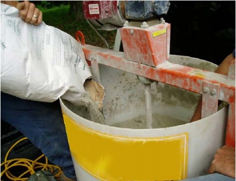
Figure 17-53 shows another grout mixing machine. In this case the person working at the abandonment of the well is placing and mixing sodium bentonite powder and water in the grout mixing machine. The mixture will be pumped from the machine through a tremie pipe placed into the well.
Figure 17-54: Abandonment Barrier Materials
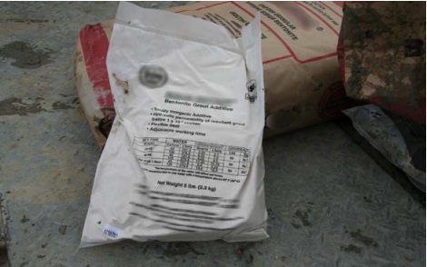
Figure 17-54 shows the back of a manufactured bentonite product package. As in this photograph, most manufacturers provide minimum volumes of material to water ratios on the back of their packages. Using proper ratios of material and water helps to achieve the best abandonment barrier for the environment.
Figure 17-55: Tremie Pipe Installed Into Drilled Well
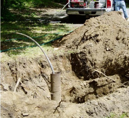
In the foreground of Figure 17-55 is a drilled well steel casing. A black tremie pipe has been installed through the top of the well casing to the well’s bottom. A hole has been excavated 2 metres (6.6 feet) below the ground surface around the well casing. In the background, sodium bentonite and clean water have been mixed in a grout mixing machine in the back of a pickup truck to achieve a mixture of 20% solids by weight.
Figure 17-56: Using Casing As Tremie Pipe
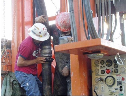
Figure 17-56 shows the attachment of a large hose on to the well casing. Both the large hose and casing will be used as the tremie pipe. In this example, cement will be pumped under pressure from a concrete pump truck through the hose and into the top of the well casing. The cement will move down the casing and into the formation below the casing. Due to the pressure exerted in the pumping operation, the cement at the bottom of the casing will push up into any open annular space located near the bottom of the well casing.
Figure 17-57: Plugging Material Displacing Uncontaminated Water
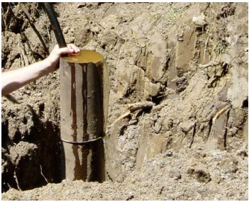
In Figure 17-57 and Figure 17-58 (below), a proper slurry mixture of sodium bentonite powder and water are being pumped into a drilled well before the mixture fully cures. In the initial phase, shown in this figure, the plugging material is rising from the bottom of the well and displaces the well water. The plugging material is placed using the tremie pipe from the bottom of the well to the top of the well casing to ensure the plugging material completely fills the well.
Figure 17-58: Plugging Material Coming Out Of Casing
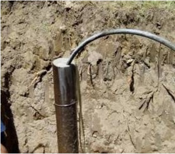
In Figure 17-58, the fluid coming out of the top of the well is the sodium bentonite plugging material (abandonment barrier). Pumping will stop and the person working at the abandonment of the well will wait in case the abandonment barrier settles out into other parts of the formation around the well. If settling occurs, the person working at the abandonment of the well will pump more plugging material into the well.
Figure 17-59: Plugging Well Including Original Annular Space with Tremie Pipe
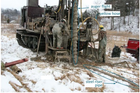
Figure 17-59 shows licensed well technicians who have finished overdrilling a well. The well technicians were able to remove the casing, well screen, riser pipe and any material in the original annular space with the auger flights. The well technicians have installed a yellow hose to a tremie pipe. The tremie pipe has been placed into the open hole (behind the auger flight). Using the rig’s pump, tremie pipe and hose, the technicians are pumping abandonment barrier slurry from a steel tub into the well.
Figure 17-60: Plugging Well Including Original Annular Space with Tremie Pipe
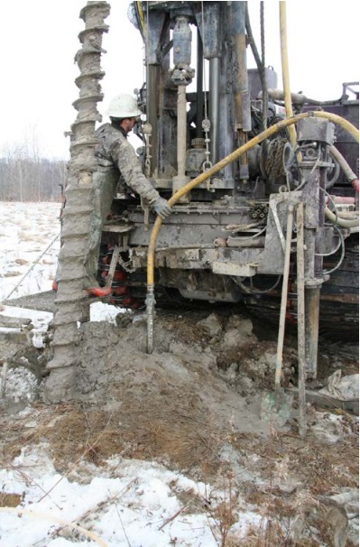
Figure 17-60 shows the same well shown in Figure 17-59. This photograph shows another view of the yellow hose attached to the tremie pipe and the tremie pipe placed into the open hole. The hole remained open because of the strength and stability of the overburden deposit. In other cases, a temporary casing or auger flight may need to be installed to hold the hole open during the placement of the abandonment barrier. Using the rig’s pump, tremie pipe and hose, the technicians are pumping abandonment barrier slurry from a steel tub into the well. The abandonment barrier is a sodium bentonite slurry.
Figure 17-61: Plugging Well with Tremie Pipe
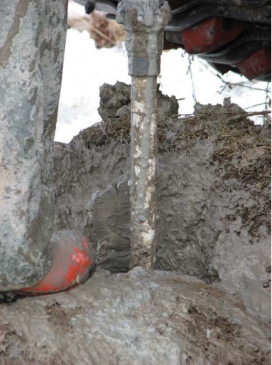
Figure 17-61 shows the same well shown in Figure 17-60. The photograph shows the tremie pipe placed into the well. The tremie pipe is placed to the bottom of the well (not shown). The hole remains open because of the strength and stability of the clay overburden deposit. In this example, a mixture of sodium bentonite and water (slurry) is being pumped under pressure through a hose and into the tremie pipe. The slurry is moving down the tremie pipe and discharging into the bottom of the hole. Due to the pressure exerted by the pump, the sodium bentonite slurry (abandonment barrier) at the bottom of the tremie pipe will push up the hole to the ground surface (see Figure 17-62 below).
Figure 17-62: Plugging Well with Tremie Pipe
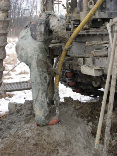
Figure 17-62 shows the same well shown in Figure 17-61 (above). The photograph shows the yellow hose clamped onto a tremie pipe. As indicated in Figure 17-61, sodium bentonite slurry (abandonment barrier) is being pumped through the hose and tremie pipe. Due to the pressure exerted by the pump, the sodium bentonite slurry (abandonment barrier) has been pushed up the open hole to the ground surface.
The intent of plugging the entire test hole or dewatering well, including the annular space, with a tremie pipe is to ensure that bridging and material segregation will not occur during grouting.
Bridging usually occurs when the plugging material is added from the ground surface into a small diameter deep drilled test hole or dewatering well at a high rate and begins to clog the hole or well casing at an elevation above the bottom of the well. This happens more frequently with dry plugging materials. As a result the material fails to properly fall to the bottom of the well creating open gaps in the abandonement barrier in the well. Open gaps, due to bridging, can potentially allow contaminants to travel vertically in the open portion of well when the casing has been pulled, destabilize the structure of well, and impede the effectiveness of the plugging materials.
Material segregation may occur when the different components of a grout (e.g., concrete) vary in weight and the grout (i.e., abandonment barrier) is poured slowly from the top of the test hole or dewatering well. This segregation reduces the effectiveness of the plugging material. As with bridging, the use of a tremie pipe can eliminate the potential of any material segregation.
3(B) Well Diameter Less Than Or Equal To 6.5 cm (2.6 inches)
These wells are typically narrow test holes, such as piezometers for measuring water levels, or monitoring wells for obtaining water samples. Point wells used in dewatering are another example of narrow diameter wells.
Reminder: When determining the diameter of a single casing test hole or dewatering well, the initial hole diameter at the time of construction must be taken into account in addition to the outer diameter of the casing.
The Wells Regulation - If the well casing and well screen have been removed, the abandonment barrier must be either:
- a slurry consisting of clean water, Portland cement and not more than 5% bentonite solids by weight; or
- a slurry consisting of clean water and at least 20% bentonite solids by weight.
The above also applies, with necessary modifications, to an uncased test hole or dewatering well that is less than or equal to 6.5 cm (2.6 inches) in diameter.
The Wells Regulation - If the well casing and well screen have not been removed, the abandonment barrier must be either:
- a slurry consisting of clean water, Portland cement and not more than 5% bentonite solids by weight, or
- bentonite chips or pellets that have been screened and placed in accordance with the manufacturer’s specifications.
The Wells Regulation - The abandonment barrier and filling materials must be installed from the bottom of the test hole or dewatering well upward to a depth of approximately 2 m (6.6ft) below the ground surface.
The Wells Regulation - Where the abandonment barrier is a slurry consisting of clean water and at least 20% bentonite solids by weight, it must be placed using a tremie pipe. The bottom of the tremie pipe must be immersed in the rising accumulation of the abandonment barrier until the required level has been reached.
There are circumstances, such as a very narrow well, that could prevent the use of a tremie pipe as defined by the Wells Regulation. As such the Wells Regulation allows for the placement of a cement mixture with no more than 5% bentonite solids by weight or bentonite chips or pellets without a tremie pipe in a well that has a diameter less than or equal to 6.5 cm (2.6 inches).
In situations where a tremie pipe is not used, there is a potential for the cement mixture or the bentonite chips or pellets to bridge due to the small diameter of the well. Extreme caution should be exercised for wells deeper than 9 m (30ft) so that the volume of plugging materials added to the well is equivalent to the volume of the well being plugged. Procedures such as pouring slowly, tamping, measuring the material level and measuring the quantity of the material added to the well should be followed [see Step 3(A) in this chapter].
3(C) Well Diameter Greater Than 65 cm (2.1ft)
These wells are typically shallow dug (i.e., excavated) test holes (e.g., test pits) or larger dewatering wells.
Reminder: When determining the diameter of a single casing well, the initial hole diameter at the time of construction must be taken into account in addition to the outer diameter of the casing. The well diameter will determine which well abandonment requirements and procedures are to be followed.
As an alternative to Step 3A in this chapter, a person can plug and seal a test hole or dewatering well up to approximately 2 metres (6.6ft) below the ground surface using the following sequential method:
i) Filling Materials in Well Screen and Water-Producing Zone
The Wells Regulation requires that clean sand or pea gravel be placed from the bottom of the well to the top of the deepest formation supplying groundwater to the well (water producing zone) or to the top of the well screen. The deepest one of the two options must be chosen.
See the following examples:
- A well record for a deep bored dewatering well shows the well was bored through a sand deposit, underlain by a clay deposit and then underlain by a gravel deposit. Both the upper sand and lower gravel deposits supply groundwater to the dewatering well. The deepest formation supplying groundwater to the well is the gravel deposit. The clean sand or pea gravel must fill the dewatering well from the bottom of the well to the top of the gravel deposit.
- Where a well screen and a water producing zone are present, the top of the water producing formation is compared to the top of the well screen and the deeper of the two measurements must be used for the location of the top of the clean sand or pea gravel.
- A intake zone on a dug dewatering well is located at the very bottom of the casing. The open bottom of the well allows a large volume of groundwater to enter into the well from the formation. However, the dewatering well also allows groundwater from the same formation to enter through the joints between concrete tiles. Unsealed joints in concrete tiles that allow groundwater to enter the well are considered to be well screen (See Chapter 2: Definitions and Clarifications, Table 2-1). In this example, the upper open joint between concrete tiles that is allowing groundwater to enter the well should be considered the top of the well screen. The clean sand or pea gravel must fill the well from the bottom of the well to the top of the joint between the concrete tiles that allows groundwater to enter the well.
If technical information is unavailable for a test hole or dewatering well such as a deep large dewatering well, further field work or site assessment may be required that could include any of the following:
- Pumping the water level to the bottom of the well and observing where groundwater is entering the well
- Installing a down-hole video camera and viewing the display to observe the interior of the well
- Drilling near the well and making observations
- Conducting a geophysical survey within the well to determine groundwater yielding formations and the location of well screen
ii) Placement of Plugging Materials
The Wells Regulation - Plugging materials are required to be placed above the clean sand or pea gravel in the test hole or dewatering well, including the annular space outside any remaining well casing.
Pouring dry plugging material from ground surface is usually sufficient to properly place it in these types of large diameter wells. Any type of slurry materials must be placed using a tremie pipe.
Bentonite Chips and Pellets
The Wells Regulation - A 0.1 metre (4 inches) thick layer of sodium bentonite chips or pellets must be placed on top of the sand or pea gravel. The sodium bentonite chips or pellets will begin to hydrate in the water and form a seal.
Well Water Level At or Below the Top of Bentonite Chips or Pellets
The Wells Regulation - In some cases, the well water level will be at or below the top of the bentonite chips or pellets that have been placed in the test hole or dewatering well. If well water is remaining above the bentonite chips or pellets placed in the well, an attempt must be made to pump the well water down to the top of the chips or pellets. If the water level can be pumped down to the top of the chips or pellets or if the water level is already at or below the required level, the following must be taken:
- Sodium bentonite powder is mixed with water to create a 20% by weight bentonite slurry as described in Table 17-4 in this chapter.
- A layer of at least 0.3 m (12 inches) of this sodium bentonite slurry mixture is placed on top of the bentonite chips or pellets.
- More bentonite slurry is placed into the test hole or dewatering well. It should be noted that this material, by itself, does not have sufficient strength to support the weight of humans, animals and vehicles.
- Clean gravel, sand, silt or clay is poured evenly over the sodium bentonite slurry surface to displace the bentonite slurry. The method should allow the materials to mix together.
- If the gravel, sand, silt or clay material rises to within 0.3 m (12 inches) below the top of the bentonite slurry then additional sodium bentonite slurry must be added to ensure that there is always 0.3 m (12 inches) of bentonite slurry at the top during the filling process.
- The process is followed until the test hole or dewatering well is filled to approximately 2 metres (6.6 feet) below the ground surface.
When Unable to Pump Well Water Down to Bentonite Chips and Pellets
The Wells Regulation - In some cases, such as deeper large diameter test holes or dewatering well, any attempts to pump the well water down to the top of the bentonite chips and pellets may be unsuccessful. In these cases, the Wells Regulation requires sodium bentonite, neat cement or concrete slurries, bentonite pellets or chips, or other materials approved by the Director to be poured or pumped into the well up to about 2 metres (6.6 feet) below the ground surface. Clean sand or pea gravel layers can be placed in any water producing zones.
Strength of Material
The Wells Regulation - The plugging abandonment barrier material installed in the test hole or dewatering well that has a large diameter must have sufficient strength to withstand the weight of humans, animals and vehicles that may move over the area for this alternate method.
4) Removing Entire Casing And Well Screen During Sealing
The Wells Regulation - If reasonably possible, the casing and the well screen must be removed (if not already removed in the previous steps) while the bottom of the casing is immersed in the rising accumulation of abandonment barrier material.
In some cases, persons who work at the abandonment of a test hole or dewatering well will:
- drive a metal tremie pipe through the interior of the well and break the bottom of the well screen,
- pump bentonite through the tremie pipe to fill the interior of the casing and well screen,
- with a cable and plug device, remove the casing and well screen from the well by lifting the casing and well screen up and around the tremie pipe, and
- pump more bentonite through the tremie pipe while raising the tremie pipe in the hole.
The method allows for the plugging and sealing of the hole while ensuring that the casing and well screen are removed. Figure 17-63 to Figure 17-68 provide photographs of the abandonment method.
Figure 17-63: Removing the Entire Casing Using Steel Tremie Pipe and Casing Puller
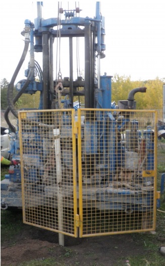
Figure 17-63 shows the back of a track mounted drill rig. Workers have placed a steel tremie pipe within the white PVC casing and well screen. Workers have pushed the steel tremie pipe through the bottom of the well screen (not shown). Workers have filled the interior of the white PVC casing and well screen (not shown) with a bentonite slurry. Workers have placed a PVC casing puller into the top of the white casing. The device is attached to cable on a track mounted drill rig. Using the casing puller and cable, workers use the drill rig to lift the white casing and well screen (not shown) out of the ground while leaving the tremie pipe in place.
Figure 17-64: Removing the Entire Casing Using Steel Tremie Pipe and Casing Puller
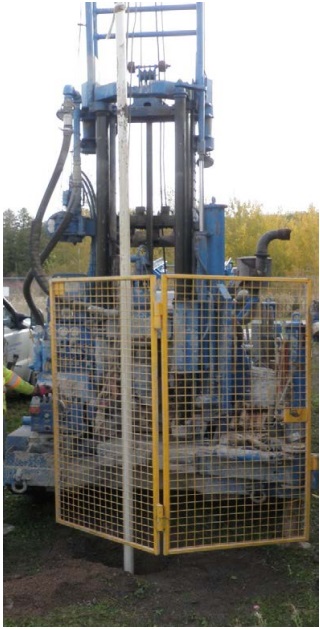
Figure 17-64 shows a similar photograph as Figure 17-63 except the workers have pulled the casing and well screen (not shown) higher up the mast of the track mounted drill rig.
Figure 17-65: Pumping Abandonment Barrier After Removing the Casing
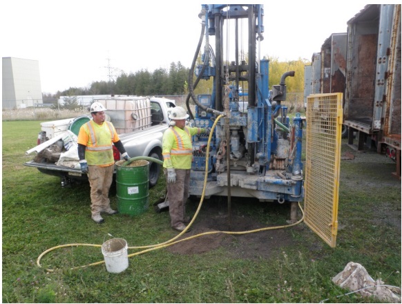
After the casing and well screen have been removed (see Figure 17-63 and Figure 17- 64) workers attach a yellow tremie line to the metal tremie pipe at the back of the track mounted drill rig. Workers prepared a bentonite slurry (not shown) in a green drum to the left of the track mounted drill rig. Workers have attached the hose from the green drum and hose from the tremie pipe to a pump on the drill rig (not shown). Workers are now pumping additional bentonite through the tremie pipe into the well.
Figure 17-66: Pumping Abandonment Barrier After Removing the Casing
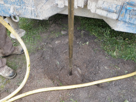
Figure 17-66 shows a close up of the tremie pipe in Figure 17-65 that is in the well. Workers are now pumping additional bentonite through the tremie pipe into the well. The pumping action allows the bentonite slurry to be released from the bottom of the tremie pipe. The force of the pumping action allows the bentonite slurry to move upward in the hole. The bentonite is displacing any material that may have collapsed into the hole and fills void or open spaces in subsurface formations and materials adjacent to the well.
Figure 17-67: Pumping Abandonment Barrier After Removing the Casing
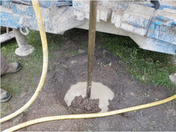
Figure 17-67 shows a close up of the tremie pipe in Figure 17-65 that is in the well. Workers have pumped additional bentonite through the tremie pipe into the well. The pumping action has forced the bentonite upward in the well and the bentonite has filled any remaining open spaces in the well and near the formation. In this case, once the bentonite cures, there will be an abandonment barrier material in the well that will prevent the vertical migration of surface water and contaminants.
Figure 17-68: Abandonment Barrier After Removing the Casing
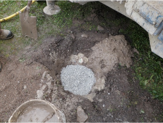
Figure 17-68 shows a close up of the sealed well in Figure 17-67 with the tremie pipe removed. Workers have added an additional layer of bentonite chips over the bentonite slurry for an additional seal at the top of the abandoned well.
Removing Casing And Well Screen For Point Well Dewatering Systems
Dewatering systems can consist of many shallow driven point wells or jetted point wells. A point well typically consists of a steel well screen within a steel point and steel risers (casing). In many cases, the point well is placed in sand or other similar formations. These formations are prone to collapse and may be prone to heaving if the casing and steel screened point are pulled from the hole.
As steel well screens, points and riser pipes are expensive to replace and many systems use hundreds of point wells, it is advantageous for well contractors to remove them after the dewatering operation has been completed. This allows well contractors to reuse the well screens, points and risers at other dewatering sites.
Unless exempt, point well dewatering systems must be properly plugged and sealed in accordance with the nine sequential steps. As the steps are sequential, the casing and well screen must not be removed before the abandonment barrier has been placed into the well.
It is a challenge to pump abandonment barrier material through the interior of the riser and out of the well screen. This will make it difficult to raise the casing while trying to fill the hole with abandonment barrier material.
Depending on the environmental conditions at the site, there may be other methods available to a well contractor for the removal of a shallow point well during proper abandonment allowing their reuse at other sites. Some examples are as follows:
- If the formation is not prone to heaving, the person who works on the abandonment of the well could use a drill/auger rig with hollow-stem auger flights. The overdrilling method could be used to create an oversized hole to the bottom of the point well as shown in Figure 17-19 and Figure 17-20. The steel well screen, point and riser(s) (casing) could be removed creating an open hole. The open hole could be filled with an abandonment barrier material. The auger flights could remain in the hole to hold the hole open. Once the required amount of abandonment barrier has been placed in the open hole, the auger flights can be removed from the hole. When the auger flights are removed, the abandonment barrier will completely fill the hole.
- The person who works at the abandonment of the well could use a simultaneous jetting and driving method (see the “Jetting and Driving Using a Drop Line and Chisel-Point Bit” section in Chapter 6: Constructing the Hole, Casing & Covering the Test Hole or Dewatering Well). The equipment could advance a temporary casing adjacent to the existing casing to the bottom of the existing point well. The jetting equipment could be removed from the temporary casing. The temporary casing could be used as a tremie pipe. An abandonment barrier, such as sodium bentonite slurry, could be pumped down the temporary casing. As abandonment barrier is pumped into the hole, the temporary casing, the existing steel well screen, point and riser(s) (casing) could be lifted from the well. The abandonment barrier discharging at the bottom of the temporary casing should fill any open spaces in the existing well and new hole. The bottom of both the original and the temporary casings must be immersed in the rising accumulation of the abandonment barrier during the process.
- The person who works at the abandonment of the well could use a driving machine to drive a temporary casing (drive rod) with an expendable driven point. The equipment could advance the expendable point and temporary casing adjacent to the existing casing to the bottom of the existing point well. The temporary casing could be used as a tremie pipe. An abandonment barrier, such as sodium bentonite slurry, could be pumped down the temporary casing. As abandonment barrier is pumped into the hole, the temporary casing is lifted off the expendable driven point. As further abandonment barrier is pumped, the temporary casing, the existing well screen, point and riser(s) (casing) could be lifted from the well. The abandonment barrier discharging at the bottom of the temporary casing should fill any open spaces in the existing well and new hole. The bottom of both the original and the temporary casing(s) must be immersed in the rising accumulation of the abandonment barrier during the process.
Figure 17-69: Removal Of Well Screen, Point And Riser(s) Using A Jetting Method
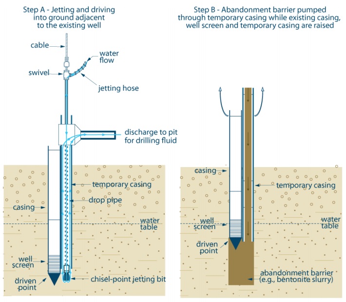
Figure 17-69 shows a cross-sectional diagram of removing a well screen, point and riser(s) that are commonly part of a construction dewatering system using a jetted method. The abandoned well in the diagram can be depicted as being originally completed into overburden or bedrock.
The diagram shows two steps, Step A (Jetting and driving into ground adjacent to the existing well) and Step B (Abandonment barrier pumped through temporary casing while existing casing, well screen and temporary casing are raised).
On the left side of the diagram, Step A shows the jetting and driving equipment being placed into the ground adjacent to the existing well. The existing well consists of a casing that extends vertically from above the ground surface into the subsurface below the water table. The bottom of the casing is attached to a well screen. A driven point is attached to the bottom of the well screen.
The jetting and driving equipment is located immediately to the right of the well. The jetting and driving equipment consists of a temporary casing that extends vertically from above the ground surface into the subsurface. The bottom of the casing is located adjacent to the well screen of the well. A connection is made at the top of the temporary casing that allows for the connection of a horizontal waterline the top of the casing. A drop pipe extends vertically from above the top of the temporary casing through the interior of the casing to the bottom of the temporary casing. The drop pipe is attached to a chisel-point jetting bit that is located below the temporary casing. A swivel attaches the top of the drop pipe to a jetting hose. A cable is attached to the top of the swivel and drop pipe. A blue line with arrows shows water flowing through the jetting house into the drop pipe and out of the chisel-point jetting bit. The water and cuttings circulate up around the drop pipe and within the temporary casing to the horizontal water line at the top of the temporary casing. The water and cuttings move through the horizontal water line and discharge to a pit for drilling fluid.
On the right side of the diagram, Step B shows the casing, well screen and driven-point of the well and temporary casing immediately adjacent to the well being pulled out of the ground. The drop pipe and chisel-point jetting bit have already been removed from the temporary casing. At this stage of removal, the well screen is located at the water table. During the removal of the well and temporary casing, abandonment barrier (e.g., bentonite slurry) is being pumped through the temporary casing and filling the void space created by the removal of the well and temporary casing.
Reminder: This figure is not to scale, it is for illustrative purposes only and does not necessarily represent full compliance with other requirements found in the Wells Regulation.
Figure 17-70: Removal Of Well Screen, Point And Riser(s) Using A Driven Method
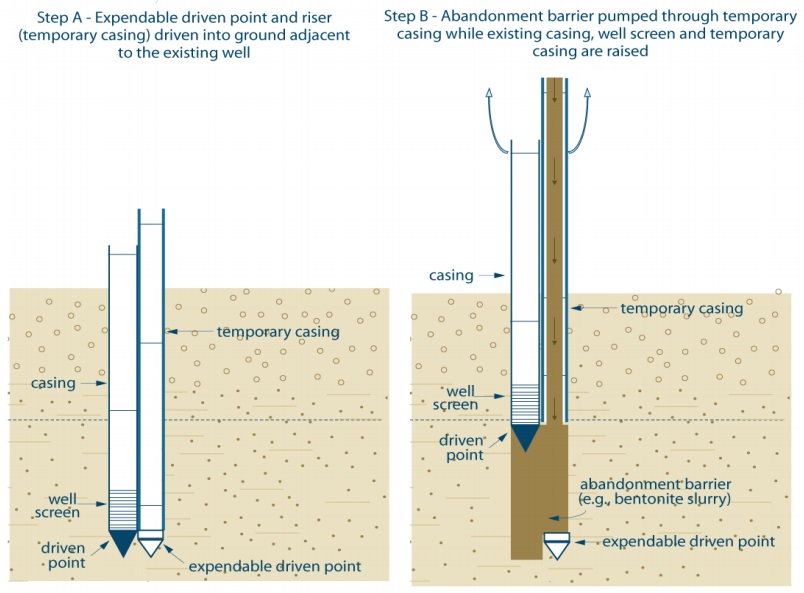
Figure 8 shows a cross-sectional diagram of removing a well screen, point and riser(s) that are commonly part of a construction dewatering system using a driven method. The abandoned well in the diagram can be depicted as being originally completed into overburden or bedrock.
The diagram shows two steps, Step A [Expendable driven point and riser (temporary casing) driven into ground adjacent to the existing well] and Step B (Abandonment barrier pumped through temporary casing while existing casing, well screen and temporary casing are raised).
On the left side of the diagram, Step A shows the driving equipment being placed into the ground adjacent to the existing well. The existing well consists of a casing that extends vertically from above the ground surface into the subsurface below the water table. The bottom of the casing is attached to a well screen. A driven point is attached to the bottom of the well screen.
The driving equipment is located immediately to the right of the well. The driving equipment consists of a temporary casing that extends vertically from above the ground surface into the subsurface. An expendable driven point is located at the bottom of the casing. The expendable driven point is located adjacent to the well’s driven-point.
On the right side of the diagram, Step B shows the casing, well screen and driven-point of the well and temporary casing immediately adjacent to the well being pulled out of the ground. The expendable driven point remains in the ground at the same location as in Step A. During the removal of the well and temporary casing, abandonment barrier (e.g., bentonite slurry) is being pumped through the temporary casing and filling the void space created by the removal of the well and temporary casing.
Reminder: This figure is not to scale, it is for illustrative purposes only and does not necessarily represent full compliance with other requirements found in the Wells Regulation.
5) Removing At Least Upper 2 Metres Of Casing
The Wells Regulation - If reasonably possible and if the casing was not removed under step 2 or step 4, at least two metres (6.6 feet) of casing below the ground surface must be removed after the abandonment barrier material has been placed in the test hole or dewatering well. The abandonment barrier material must be placed up to a depth of about 2 metres (6.6 feet) below the ground surface (see Step 3 in this chapter).
A well opening needs to be created to expose the well casing to a minimum depth of two metres below the ground surface prior to its removal. When using an excavator, such as a backhoe or highhoe, a significant hole is created around the well casing. After the hole has been created the person working at the abandonment of the test hole or dewatering well must take necessary safety measures to cut and remove at least two metres of casing below the ground surface.
Reminder: During the excavation to remove the top 2 m (6.6 feet) of casing, any flush-mounted well pit (vault) structure can also be removed (see the “Test Holes or Dewatering Wells within Well Pits and Flush- Mounted Well Pits (Vaults)” section of this chapter for further information).
Figure 17-71: Removing Two Metres Of Well Casing
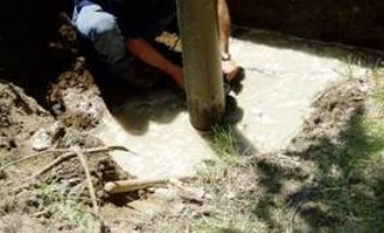
Figure 17-71 shows a licensed well technician removing at least 2 metres (6.6 feet) of well casing from the abandoned well after filling the well with plugging material. Proper safety procedures including shoring and/or sloping the sides of the well opening excavation need to be followed.
Figure 17-72: Cut Casing With Abandonment Barrier
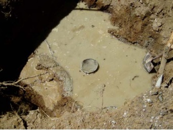
In Figure 17-72, the top of the casing is cut off and abandonment barrier material is shown inside the remaining casing and also in the well opening (excavated hole) around the well.
Another method of removing casing is to use a casing cutting device. The device is attached to drilling tools and lowered by the drill machine into the test hole or dewatering well (see Figure 17-39 and Figure 17-40 in this chapter). The cutting device can easily cut the well casing from the inside at a depth of at least 2 metres (6.6 feet) below the ground surface. Both the casing and the cutting device can be pulled from the well using the drill machine.
Reminder: For large diameter test holes or dewatering wells, including well pits, a large excavator is usually needed to lift and remove large concrete tile or galvanized steel casing. During the removal process of large diameter concrete well casing, any broken concrete tiles must be removed from the well before proceeding with further plugging and sealing steps.
In other cases, the upper portion of the well casing may be sealed into bedrock or within a building. In these cases, where removal of the upper two metres of the casing is not reasonably possible, the upper portion of the well casing may be left intact.
Best Management Practice – Removing the Casing
In all cases, the complete removal of casing prior to or during the placement of the abandonment barrier material is the preferred option.
6) Using Cement Or Concrete
The Wells Regulation - If the abandonment barrier contains cement, it must set until firm and, if necessary (e.g., if it settles out into the formation), it must be topped up to approximately 2 metres (6.6 feet) below the ground surface.
7) Removing Below Ground Concrete Structures And Slabs
The Wells Regulation - Well pits, structures and slabs are sometimes removed before the test hole or dewatering well is plugged during step 2. However, this can also be done during the abandonment process at any time before the sealing of the upper 2 m (6.6 feet) of the well opening. Any below ground concrete structures, foundations and slabs must be removed unless the remaining structures (e.g., a building) may become destabilized, damaged or unsafe when the underground slabs or structures are removed.
The structures must be removed to at least a depth adequate to accommodate the sealing measures.
Best Management Practice – Sealing and Decommissioning any Waterlines and Related Equipment
It is important to properly seal and decommission any waterlines and related equipment (e.g., a large diameter conduit that surrounds the waterlines) that extend underground from a test hole or dewatering well to a building. If not properly decommissioned, the underground waterline and related equipment may act as a pathway for surface water and other foreign materials to gain access to the building, or to flow toward the area of the abandoned test hole or dewatering well.
8) Plugging and Sealing the Upper 2 Metres (6.6 feet) of the Well Opening
The Wells Regulation - To prevent inadvertent or unauthorized access, the test hole or dewatering well and the well opening (which includes any excavation) must be sealed up to the ground surface by:
- placing 50 cm (1.6 ft) to 150 cm (5 ft) in vertical thickness of bentonite chips, pellets, granules or powder in accordance with the manufacturer’s specifications, and
- filling the remaining well and well opening above the layer of bentonite and up to the ground surface with soil cover or other material that is more in keeping with the existing material immediately adjacent to the well opening.
An example of an “other material” that is more in keeping with the existing material immediately adjacent to the well opening is concrete for test holes or dewatering wells within buildings or on sidewalks.
Best Management Practice – Bentonite Chips, Pellets, Granules or Powder
When placing manufactured bentonite chips, pellets, granules or powder in the well opening, they should be fully hydrated to ensure bentonite is fully expanded and prevent any future up-heaving of the ground surface. Care should be taken to estimate the depth of bentonite needed in the well opening by taking into account the significant expansion of bentonite after hydration.
As each environment is unique, the thickness and type of bentonite and the placement method used to fill the well opening should be determined on a case by case basis to ensure that the thickness remains in the required range after filling the well opening. These considerations are important to prevent any collapse at the well opening if a vehicle, animal or human passes over the abandoned well and to offer the best protection to the environment.
Figure 17-73: Placing Bentonite Pellets on Top of Abandonment Barrier
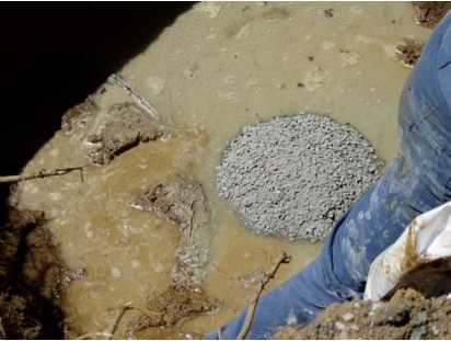
Figure 17-73 shows bentonite pellets being placed in the well opening (excavation) on top of abandonment barrier material (bentonite) in a drilled well (see Figure 17-72). Bentonite pellets need to fill the entire well opening and be at least 50 cm (1.6ft) to 150 cm (5ft) thick.
9) Stabilizing Disturbed Area
The Wells Regulation - The area of the ground surface where the well is located must be covered and stabilized to prevent any erosion.
For example, this can be achieved by seeding grass or sodding the area of the filled well opening on a golf course or lawn.
Best Management Practice – Filling and Stabilizing Well Opening
The material placed in the well opening has sufficient strength to hold the weight of humans, animals and vehicles.
Diagrams Of Plugged And Sealed Wells
Figure 17-74 to Figure 17-79 provide examples of various well types that have been plugged and sealed based on the nine step sequential process.
Reminder: All figures and diagrams are not to scale, are for illustrative purposes only and do not necessarily represent full compliance with other requirements found in the Wells Regulation.
Figure 17-74: Plugging And Sealing Wells > 6.5 cm (2.5 inches)
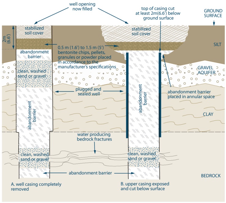
Figure 17-74 shows a cross-sectional diagram of two methods of plugging and sealing test holes or dewatering wells that are greater than 6.5 cm (2.5 inches) in diameter. The two abandoned wells in the diagram were originally constructed through the overburden and completed into the bedrock.
The example on the left side of the diagram shows the plugging and sealing of the well with the casing completely removed.
From about 2 metres below the ground surface to the bottom of the well, the example on the left shows clean, washed sand or gravel placed in the well bore adjacent to water producing zones or fractures, to minimize the loss of sealant material and the remainder filled with an abandonment barrier material.
From about 2 metres below the ground surface to the ground surface, the example on the left shows a layer of 50 and 150 centimetres (1.6 to 5 feet) in vertical thickness of bentonite chips, pellets, granules or powder placed in the well opening in accordance with the manufacturer’s specifications, and the remaining well opening to the ground surface filled with soil cover, or other material that is more in keeping with the surface material immediately adjacent to the well opening, to prevent inadvertent or unauthorized access.
The example on the right side of the diagram shows the plugging and sealing of the well with the upper 2 metres (6.6 feet) of casing removed.
From about 2 metres (6.6 feet) below the ground surface to the bottom of the well, the example on the right shows clean, washed sand or gravel placed in the well bore adjacent to water producing zones or fractures, to minimize the loss of sealant material and the remainder filled with an abandonment barrier material.
From about 2 metres (6.6 feet) below the ground surface to the ground surface, the example on the right shows a layer of 50 and 150 centimetres (1.6 to 5 feet) in vertical thickness of bentonite chips, pellets, granules or powder placed in the well opening in accordance with the manufacturer’s specifications, and the remaining well opening to the ground surface filled with soil cover, or other material that is more in keeping with the surface material immediately adjacent to the well opening, to prevent inadvertent or unauthorized access.
- This procedure is typically used for drilled wells and may also be used for direct push, dug and bored wells. It is permitted for any type of well with a diameter greater than 6.5 cm (2.5 inches).
- Abandonment barrier slurries must be placed using a tremie pipe.
- Abandonment barrier must prevent any movement of water, natural gas, contaminants or other materials between subsurface formations (including aquifers) and between a subsurface formation (including an aquifer) and the top of the abandonment barrier.
- Water should be added to the bentonite chips, pellets, granules or powder to start hydration.
- Soil cover can be other material in keeping with existing adjucent surface material. The soil cover must prevent inadvertent and unauthorized access.
- Well opening is typically excavated to remove the top portion of the well casing.
Reminder: This figure applies to situations where narrow diameter wells (≤ 6.5 cm) are overdrilled to a diameter > 6.5 cm. It also applies to test holes or dewatering wells with a diameter > 6.5 cm that are constructed with flush-mounted well pits (vaults).
Reminder: The diagram above is not to scale, it is for illustrative purposes for this chapter only and it does not necessarily represent full compliance with other requirements found in the Wells Regulation.
Figure 17-75: Plugging And Sealing Narrow Diameter Wells < 6.5 cm (2.5 inches)
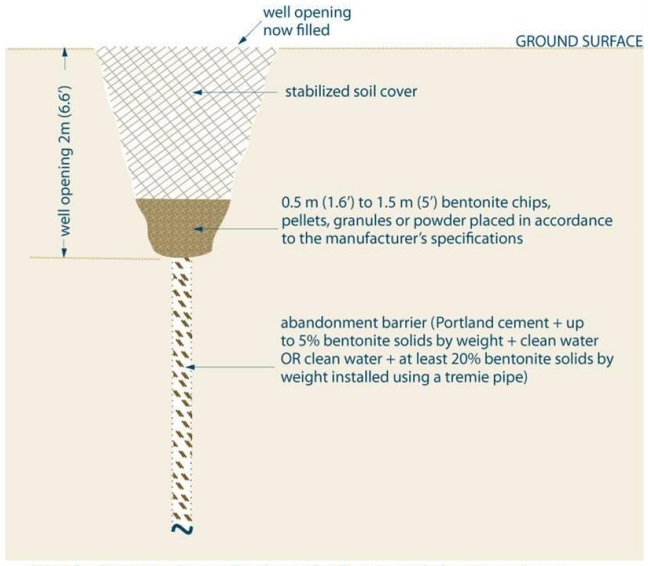
Figure 17-75 shows a cross-sectional diagram of one method of plugging and sealing narrow test holes or dewatering wells that are less than or equal to 6.5 cm (2.5 inches) in diameter. The abandoned well in the diagram can be depicted as being originally completed into overburden or bedrock.
The example shows the plugging and sealing of the well with the casing completely removed.
From about 2 metres (6.6 feet) below the ground surface to the bottom of the well, the example shows the well filled with an abandonment barrier material that consists of Portland cement and up to 5 percent solids by weight plus clean water or, as an alternate, clean water plus at least at least twenty percent bentonite solids by weight installed using a tremie pipe.
From about 2 metres (6.6 feet) below the ground surface to the ground surface, the example shows a layer of 50 and 150 centimetres (1.6 to 5 feet) in vertical thickness of bentonite chips, pellets, granules or powder placed in the well opening in accordance with the manufacturer’s specifications, and the remaining well opening to the ground surface filled with soil cover, or other material that is more in keeping with the surface material immediately adjacent to the well opening, to prevent inadvertent or unauthorized access.
- This is for situations where well casing and well screen are being removed or are absent.
- This is typically for narrow diameter drilled, jetted and driven point wells
- Abandonment barrier must prevent any movement of water, natural gas, contaminatnts or other materials between subsurface formations (including aquifers), and between a subsurface formations (including and aquifer), and the top of the abandonment barrier
- Water should be added to the bentonite chips, pellets, granules or powder to start hydration
- Well opening is typically excavated to remove the top portion of the well casing.
Reminder: This figure and associated notes apply to situations where narrow diameter wells (≤ 6.5 cm) are constructed with flush-mounted well pits (vaults) and the casing and well screen have been removed.
Reminder: The diagram above is not to scale, it is for illustrative purposes for this chapter only and it does not necessarily represent full compliance with other requirements found in the Wells Regulation.
Figure 17-76: Plugging and Sealing a Test Hole or Dewatering Well With a Diameter ≤6.5 cm and was Completed with a Flush-mounted Well Pit
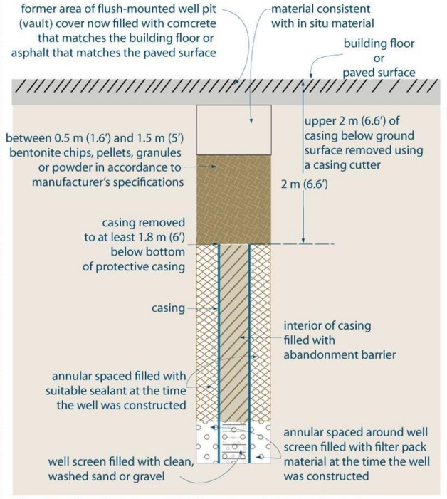
Figure 17-76 shows a cross-sectional diagram of one method of plugging and sealing a test hole or dewatering well that is less than or equal to 6.5 cm (2.5 inches) in diameter and with a flush-mounted well pit (vault). The abandoned well in the diagram can be depicted as being originally completed into overburden or bedrock.
The example shows the plugging and sealing of the well with the upper 2 metres (6.6 feet) of casing removed. There is a well screen attached to the bottom of the casing. The annular space around the well screen is filled with filter pack material. The annular space around the casing is filled with suitable sealant.
From about 2 metres (6.6 feet) below the ground surface to the bottom of the casing of the well, the example shows the interior of the well filled with an abandonment barrier material. The interior of the well screen is filled with clean, washed sand or gravel.
From about 2 metres (6.6 feet) below the ground surface to the ground surface, the example shows a layer of 50 and 150 centimetres (1.6 to 5 feet) in vertical thickness of bentonite chips, pellets, granules or powder placed in the well opening in accordance with the manufacturer’s specifications. The remaining well opening to the ground is filled with material consistent with in-situ material. The top of the ground surface is considered a building floor or a paved surface. The former area of the flush-mounted well pit (vault) cover is now filled with concrete that matches the building floor or asphalt that matches the paved surface.
- If casing and well screen are not being removed, the abandonment barrier must be:
- A slurry of clean water and Portland cement + up to 5% bentonite solids by weight, or
- Bentonite chips or pellets that have been screened and placed in accordance with manufacturer’s specifications.
- At least the top 2m (6.6ft) of the casing must be removed, if reasonably possible.
- Well opening is typically excavated to remove the top portion of the well casing.
Reminder: This figure and associated notes apply to situations where narrow diameter wells (≤6.5 cm) are constructed with flush-mounted well pits (vaults) and the casing and well screen have not been removed.
Reminder: The diagram above is not to scale, it is for illustrative purposes for this chapter only, and it does not necessarily represent full compliance with other requirements found in the Wells Regulation. It does not include additional considerations such as structural design.
Figure 17-77: Plugging And Sealing Large Diameter Wells > 65 cm (2.5ft) - Alternate Methods
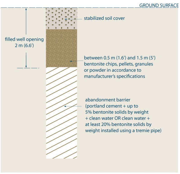
Figure 17-77 shows a cross-sectional diagram of one method of plugging and sealing an uncased narrow test hole or dewatering well that is less than 6.5 cm (2.5 inches) in diameter. The abandoned well in the diagram can be depicted as being originally completed into overburden or bedrock.
The example shows the plugging and sealing of the well when the casing and well screen were not originally installed.
From about 2 metres (6.6 feet) below the ground surface to the bottom of the well, the example shows the well filled with an abandonment barrier material that consists of Portland cement and up to 5 percent solids by weight plus clean water or, as an alternate, clean water plus at least at least twenty percent bentonite solids by weight installed using a tremie pipe.
From about 2 metres (6.6 feet) below the ground surface to the ground surface, the example shows a layer of 50 and 150 centimetres (1.6 to 5 feet) in vertical thickness of bentonite chips, pellets, granules or powder placed in the well opening in accordance with the manufacturer’s specifications, and the remaining well opening to the ground surface filled with stabilized soil cover.
- This is for situations where well casing and well screen were never installed.
- This is typically for narrow diameter drilled, direct push wells.
- Abandonment barrier must prevent any movement of water, natural gas, contaminants or other materials between subsurface formations (including aquifers), and between a subsurface formations (including an aquifer), and the top of the abandonment barrier.
- Water should be added to the bentonite chips, pellets, granules or powder to start hydration.
Reminder: The diagram above is not to scale, it is for illustrative purposes for this chapter only and it does not necessarily represent full compliance with other requirements found in the Wells Regulation.
Figure 17-78: Plugging And Sealing Uncased Narrow Diameter Well <6.5 cm (2.5 inches)
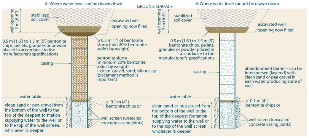
Figure 17-78 shows a cross-sectional diagram of two alternate methods of plugging and sealing test holes or dewatering wells that are greater than 65 cm (2.5 feet) in diameter. The two abandoned wells in the diagram were originally constructed into the overburden and below the water table.
The example on the left is of the diagram is example “A” and illustrates the scenario where the water level can be drawn down in the well. The example on the right is example “B” and illustrates the where the water level cannot be drawn down in the well.
Both examples (A and B) show the plugging and sealing of the well with the upper 2 metres (6.6 feet) of casing removed. The casing is made up of concrete tiles. The bottom concrete tiles below the water table are considered well screen as the concrete casing joints are unsealed.
From about 2 metres below the ground surface to the bottom of the well, both examples show clean, sand or pea gravel placed from the bottom of the well to the top of the deepest formation supplying water to the well or to the top of the well screen, whichever is deeper. A layer that is greater than or equal to 0.1 metre (0.4 inches) of bentonite chips is placed on top of the clean sand or pea gravel.
Example A shows a layer of bentonite slurry (minimum 20 percent bentonite solids by weight) mixed with clean gravel, sand, silt or clay (placement is important) is placed in the well on top of the bentonite chips. A layer that is greater than or equal to 0.3 metres (1 foot) of bentonite slurry (minimum 20 percent bentonite solids by weight) is placed on top of the bentonite mixed with gravel, sand, silt or clay. The top of the bentonite slurry shall be about 2 metres (6.6 feet) below the ground surface.
From about 2 metres below the ground surface to the ground surface, example A shows a layer of 50 and 150 centimetres (1.6 to 5 feet) in vertical thickness of bentonite chips, pellets, granules or powder placed in the well opening in accordance with the manufacturer’s specifications, and the remaining well opening to the ground surface filled with soil cover, or other material that is more in keeping with the surface material immediately adjacent to the well opening, to prevent inadvertent or unauthorized access.
From about 2 metres below the ground surface to the bottom of the well, example B shows clean, washed sand or gravel placed in the well bore adjacent to water producing zones or fractures, to minimize the loss of sealant material and the remainder filled with an abandonment barrier material.
Example B shows a layer of abandonment barrier placed on top of the bentonite chips. The abandonment barrier can be interspersed (layered) with clean sand or pea gravel in each water producing zone. The top of the abandonment barrier shall be about 2 metres (6.6 feet) below the ground surface.
From about 2 metres below the ground surface to the ground surface, example B shows a layer of 50 and 150 centimetres (1.6 to 5 feet) in vertical thickness of bentonite chips, pellets, granules or powder placed in the well opening in accordance with the manufacturer’s specifications, and the remaining well opening to the ground surface filled with soil cover, or other material that is more in keeping with the surface material immediately adjacent to the well opening, to prevent inadvertent or unauthorized access.
- This alternate method is typically large diameter dug, bored or augered wells.
- Abandonment barrier slurries must be placed using a tremie pipe.
- Soil cover can be other material in keeping with existing adjacent surface material. The soil cover must prevent inadvertent and unauthorized access.
- Abandonment barrier must prevent any movement of water, natural gas, contaminatnts or other materials between subsurface formations (including aquifers), and between a subsurface formation (including an aquifer), and the top of the abandonment barrier.
- Water should be added to the bentonite chips, pellets, granules or powder to start hydration.
- Well opening is typically excavated to remove the top portion of the well casing.
Reminder: The well in Diagram ‘A’ of Figure 17-78, above, is filled with a bentonite slurry (minimum 20% bentonite solids by weight) + clean gravel, sand, silt or clay. In this case, the placement method is important. See the placement method in step 3(C) in this Chapter.
Reminder: The diagram above is not to scale, it is for illustrative purposes for this chapter only, and it does not necessarily represent full compliance with other requirements found in the Wells Regulation.
Figure 17-79: Plugging And Sealing A Drilled Well Through A Large Diameter Dug Well Or Well Pit
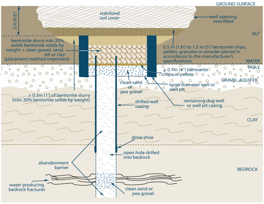
Figure 17-79 shows a cross-sectional diagram of one method of plugging and sealing a drilled test hole or dewatering well through a large diameter dug well or well pit. The abandoned well is completed through the overburden and completed into the bedrock. The drilled portion of the well encountered groundwater in water producing bedrock fractures. The drilled portion of the well has a casing that extends vertically from within the dug well into the upper portion of the bedrock. A drive show is attached to the bottom of the casing. The top of the casing is located 2 metres below the ground surface. The remainder of the drilled well in the bedrock is an open hole.
A clay overburden deposit overlies the bedrock. A gravel overburden deposit overlies the clay and contains an aquifer. A silt deposit overlies the gravel to the ground surface. The water table is located at the silt – gravel interface. The dug portion of the well encountered groundwater in the gravel aquifer. The remaining dug well or well pit casing extends vertically from 2 metres below the ground surface to within the gravel deposit.
From about the bottom of the dug well to the bottom of the well, the drilled portion of the well is filled with clean sand or pea gravel placed in the well bore adjacent to water producing fractures, to minimize the loss of sealant material and the remainder filled with an abandonment barrier material.
From about 2 metres below the ground surface to the bottom of the dug well or well pit, clean sand or pea gravel is placed from the bottom of the dug well (or well pit) to the top of the gravel aquifer (which is also the water table). A layer greater than or equal to 0.1 metre (0.4 inches) of bentonite chips is placed on top of the clean sand or pea gravel. A layer of bentonite slurry (minimum 20 percent bentonite solids by weight) mixed with clean gravel, sand, silt or clay (placement method is important) is placed in the well on top of the bentonite chips. A layer that is greater than or equal to 0.3 metres (1 foot) of bentonite slurry (minimum 20 percent bentonite solids by weight) is placed on top of the bentonite mixed with gravel, sand, silt or clay. The top of the bentonite slurry shall be about 2 metres (6.6 feet) below the ground surface.
From about 2 metres below the ground surface to the ground surface, a layer of 50 and 150 centimetres (1.6 to 5 feet) in vertical thickness of bentonite chips, pellets, granules or powder is placed in the well opening in accordance with the manufacturer’s specifications, and the remaining well opening to the ground surface is filled with stabilized soil cover.
- Requirments for wells > 6.5 cm (2.5 inches) apply to the drilled portion of the well, and alternate method for wells > 65 cm (2.5ft) could be used from the bottom of the dug well or well pit up to the ground surface.
- Abandonment barrier slurries must be placed using a tremie pipe.
- Soil cover can be other amterial in keeping with existing adjusting surface material.
- The abandonment barrier must be prevent any movement of water, natural gas, contaminnants or other materials between subsurface formations (including aquifers) and between a subsurface formation (including an aquifer), and the top of the abandonment barrier.
- Water should be added to the bentonite chips, pellets, granules or powder to start hydration.
- Well opening is typically excavated to remove the top portion of well casing.
Reminder: If water cannot be pumped down to the top of the 0.1 m (4 inches) of bentonite chips or pellets see Figure 17-78(B) and step 3(C) in this chapter for material placement method. If present, a well pit floor made of suitable sealant must be removed in this case to allow for the placement of clean sand or pea gravel.
Reminder: The diagram above is not to scale, it is for illustrative purposes for this chapter only, and it does not necessarily represent full compliance with other requirements found in the Wells Regulation.
Abandonment Of Flowing Test Holes and Dewatering Wells
Where flowing test holes or dewatering wells cannot be properly controlled or stopped during well construction, they must be properly abandoned. In these cases, the person abandoning the test hole or dewatering well must ensure that the person who works on the abandoned well properly plugs and seals the well to prevent the movement of the free flowing water. Properly plugging and sealing the test hole or dewatering well should restore the aquifer to its original condition (i.e., prior to the construction of the well).
The Wells Regulation - The cost associated with the abandonment is to be absorbed by the well contractor unless a previously established written contract expressly releases the well contractor from the cost.
Reminder: Only licensed well contractors and well technicians with experience in flowing test holes and dewatering wells should attempt to plug flowing wells.
Reminder: The exemptions for a “shallow works” do not apply if the test hole or dewatering well is constructed in an area likely to result in a flowing well, or becomes a flowing well. In these circumstances, the Wells Regulation requirements, including the abandonment requirements, outlined in this section apply. See Chapter 3: Exemptions: Wells, Activities & Experienced Professionals for further information on shallow works.
If Flow At Surface Can Be Controlled Using Weighted Fluids
The flow at the surface from the aquifer can be controlled using weighted drilling fluids (muds). Weighted drilling fluids include bentonite based drilling muds with barite additives. Once the flow is controlled using weighted drilling fluids, the abandonment can usually be successfully carried out using a high specific gravity cement based grout, such as neat cement or concrete. In many cases, the casing needs to be removed to expose the upper portion of the water producing zone. This will allow for the concrete or cement to more effectively seal the hole and fill any cavities that may have formed around the outside of the well casing, and restore the aquifer to its original condition.
The downhole hydrostatic head pressure and downward grout pressure need to be calculated to determine the type of material (e.g., concrete) needed to stop the flow of groundwater from the aquifer (see Chapter 11: Flowing Test Holes & Dewatering Wells for additional information). This abandonment barrier must be placed upward from the bottom of the well using a tremie pipe.
The Wells Regulation - If the test hole or dewatering well is a flowing well, commercially manufactured drilling mud may be used to assist with drilling or the placement of an abandonment barrier. The drilling mud must not impair the quality of the water that it comes into contact with and it is not allowed to be used as an abandonment barrier.
Only licensed well contractors and well technicians with experience in flowing well construction should attempt to plug flowing wells.
If Flow At Surface Cannot Be Controlled Using Weighted Grouts
If it is not possible to control the flow using weighted grouts, then it may be necessary to offset and drill a properly constructed depressurization (relief) well or wells. These relief wells must be constructed and pumped to reduce the flowing head conditions at the encountered well. Once the flowing conditions are controlled, proper abandonment of the flowing well can proceed. However, extreme caution must be used when constructing the relief wells as there have been many cases where the relief wells did not work or became problem flowing wells themselves. The relief wells would then have to be properly abandoned.
In some cases other techniques have successfully been used to temporarily stop the flow of water from the well to allow for the placement of abandonment material. These include: raising the casing above the static water level and freezing with liquid nitrogen to temporarily seal the aquifer around the well.
Best Management Practice – Retaining Professional Expertise
The person abandoning the well should consider retaining a Professional Geoscientist or Professional Engineer to determine the type of abandonment barrier materials to use in the abandonment of the flowing well and to prepare a design to plug and seal the flowing well.
Figure 17-80 to Figure 17-85 show the specialized equipment and materials necessary to seal a high pressure flowing well to protect property, surface water and prevent adverse effects on the natural environment.
Figure 17-80: Flowing Well aT Back of Drilling Rig
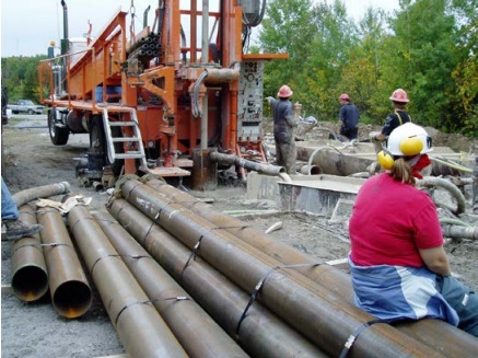
Figure 17-80 shows the casing of the drilled well extending just above the ground surface behind the drill rig. The drill rods are attached to the drill rig and extend down into the well casing. In this case, the well is approximately 21 m (69ft) deep. Groundwater and drilling mud are flowing from the working casing to a horizontal pipe and discharging into a tank. Flowing water from the well cannot be stopped and is freely flowing into the tank with the drilling mud. The discharged material and water are directed into a prepared and approved sediment discharge and settling area on the site. In this case, the well driller could not stop the high pressure of the flowing groundwater out of the well with a weighted drilling mud and had to abandon the well (see Figure 17-81 to Figure 17-85).
Figure 17-81: Attaching Tremie Pipe To Truck
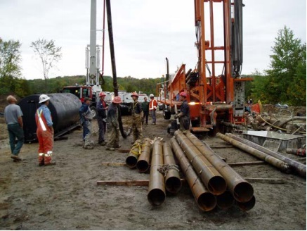
In Figure 17-81 the consultants and drillers determined the best way to seal this high pressure flowing well was to remove nearly all of the well casing in the well. The consultant calculated that 3.5 cubic metres (123.6 cubic feet) of concrete would supply sufficient weight to overcome the downhole hydrostatic head pressure and stop the flow. The consultant also determined a high pressure specialized cement pump truck would be necessary to pump the concrete at a high rate into the hole to ensure the material’s weight would quickly overcome the groundwater’s downhole hydrostatic head pressure. Figure 17-81 shows the persons working on the abandoned well attaching the top of the tremie pipe to the cement pump truck (on left side of photograph).
Figure 17-82: Tremie Pipe Lowered Into Flowing Well
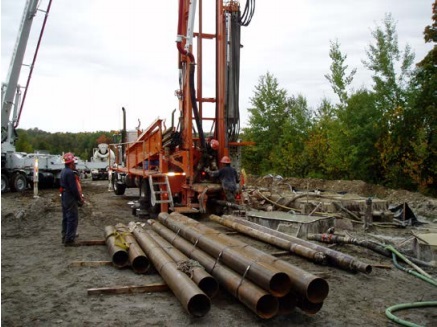
Figure 17-82 shows the tremie pipe (behind the drill rig) going into the flowing well from Figure 17-80. The bottom of the tremie pipe was installed near the bottom of the well. In the background, a cement truck and cement pump truck are standing by to start the pumping operation.
Figure 17-83: Concrete Pumping Operation
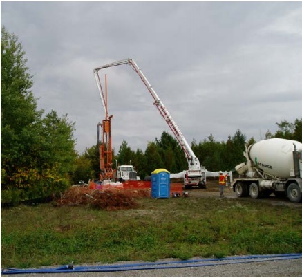
Figure 17-83 shows the cement pump truck with its boom in the air and over the drill rig almost prepared for the pumping of concrete into the flowing well from Figure 17-80. The cement truck is backing up to the cement pump truck to begin the plugging operation.
Figure 17-84: Pumping Concrete
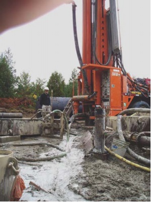
Figure 17-84 shows the concrete being pumped at a high rate into the flowing well from Figure 17-80. The concrete is displacing the remaining water in the well. The water is discharging from the well onto the surface and into a controlled sediment settling area. The consultant and well owner had obtained a Permit to Take Water since the flowing well was discharging at a rate greater than 50,000 litres per day.
Figure 17-85: Flow Stopped
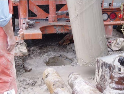
Figure 17-85 shows that the placement of 3.5 cubic metres (123.6 cubic ft) of concrete within a few minutes has stopped the flow of water out of the well. The aquifer has been sealed and restored to its original state. The concrete will cure and act as a permanent seal. The entire well casing was removed exposing the open hole at surface. The upper portion of the well opening will be properly plugged.
Wells Within Well Pits and Flush-mounted Well Pits (Vaults)
When a test hole or dewatering well is to be abandoned, the Wells Regulation requires the filling, plugging and sealing of the entire test hole or dewatering well. Different materials and filling procedures apply to wells of different diameters.
In some cases, test holes or dewatering wells are installed in well pits including flush-mounted well pits (vaults). For the purpose of well abandonment, well pits, including flush-mounted well pits (vaults), are considered wells and must be properly plugged and sealed as outlined in this chapter and in the Wells Regulation.
For test holes or dewatering wells with well pits that are greater than 65 cm (26 inches) in diameter the following abandonment barrier requirements apply:
- the portion of the well inside the well pit (less than or equal to 65 cm (26inches)) must be plugged with abandonment barrier in accordance with step 3(A) or 3(B), depending on the diameter of the test hole or dewatering well, up to about 2 m (6.6 feet) below the ground surface, and
- the large diameter portion of the well pit must be plugged with abandonment barrier in accordance with step 3 (A) or as an alternative step 3 (C) up to about two metres below the ground surface.
For test holes or dewatering wells with well pits, including flush-mounted well pits (vaults), which are less than 65 cm (26 inches) in diameter the following abandonment barrier requirements apply:
- the portion of the well inside the well pit [less than or equal to 65 cm (26 inches)] must be plugged with abandonment barrier in accordance with step 3(A) or step 3(B), depending on the diameter of the test hole or dewatering well, up to about two metres below the ground surface.
Commercially manufactured flush-mounted well pits (vaults) are less than 65 cm (26 inches) in diameter. Common manufactured flush-mounted well pits (vaults) range from 15.2 cm (6 inches) to 35 cm (13.5 inches) across and 15.2 cm (6 inches) to 61 cm (24 inches) deep.
With respect to the removal of both large and small diameter casings, a person must follow steps 2, 4 and 5 of the nine sequential steps to plug and seal a test hole or dewatering well. The flush-mounted well pits (vaults) must be removed as part of these steps, if reasonably possible.
The person abandoning the test hole or dewatering well must then follow the remaining steps (6 to 9) to complete the filling, plugging and sealing of the abandoned test hole or dewatering well. This includes:
- placing 0.5 m (1.6 feet) to 1.5 m (5 feet) bentonite chips, pellets or granules in the upper 2 m of the test hole or dewatering well, and
- filling the remaining portion of the well to ground surface with soil cover or other material that is more in keeping with the existing material immediately adjacent to the well opening. Examples of other material can include:
- concrete for test holes or dewatering wells within buildings or on sidewalks, or
- asphalt for test holes or dewatering wells on roads.
Reminder: There are many cases of existing test holes or dewatering wells housed in well pits including flush-mounted well pits (vaults). Over time, some of these pits may allow contaminants and/or surface water to enter the test hole or dewatering well and may cause groundwater mounding. For improved maintenance and sanitary protection, some test holes or dewatering wells are being altered to extend the top of the well casing above the ground surface and the well pits are being plugged and sealed. If the well owner decides to continue to use the well with the new casing extension, and to abandon the well pit:
- the person abandoning the well pit portion of the well must ensure the well pit is abandoned, with necessary modifications, as if it were a well
- the person constructing (altering) the well and the well owner should review the information in the “Extension of Well Casing for a Well in a Well Pit” section in Chapter 14: Test Hole & Dewatering Well Maintenance & Repair
Reminder: For examples of wells in well pits, refer to Figure 17-6 and Figure 17-7. For examples of properly abandoned wells in well pits, refer to Figure 17-76 and Figure 17-79.
Excavating The Entire Test Hole or Dewatering Well
If a test hole or dewatering well is abandoned by excavating the entire well in the course of work carried out for another purpose, then the person abandoning the well, often the well owner, does not need to ensure that the well is abandoned in accordance with the nine step sequential process. In this case, the person abandoning the well, often the well owner, must ensure that:
- the “Obligation to Retain a Licensed Well Contractor” or the “Exemption - Obligation to Retain a Licensed Well Contractor” sections in Chapter 4: Well Contractors & Well Technicians – Licences, Responsibilities & Exemptions are followed,
- the well tag, if present, is returned to the Director within 30 days after its removal, and
- unless exempt, a well record is completed and submitted as described in Chapter 15: Well Records, Documentation, Reporting & Tagging.
Reminder: A person can abandon a well before it is completely excavated. In this case, the person abandoning the well, often the well owner, must ensure that:
- the “Obligation to Retain a Licensed Well Contractor” or the “Exemption - Obligation to Retain a Licensed Well Contractor” sections in Chapter 4: Well Contractors & Well Technicians – Licences, Responsibilities & Exemptions are followed,
- the well is abandoned following the nine sequential step approach described in this chapter, and
- unless exempt, a well record is completed and submitted as described in Chapter 15: Well Records, Documentation, Reporting & Tagging.
Work carried out for another purpose that involves the entire removal of the test hole or dewatering well by excavation could include any of the following:
- Installing a new building foundation
- Excavating elevator shafts
- Removing overburden and other materials that are on a contaminated site
- Excavating to create a pond, trench or lagoon
- Excavating in an open pit mine, quarry or sand and gravel pit
Reminder: A plan for development at a site that may excavate an entire test hole or dewatering well in the future does not exempt the well owner from the requirement to immediately abandon a test hole or dewatering well that is not being used or maintained for future use as a test hole or dewatering well. In these cases, the person abandoning the test hole or dewatering well must follow the nine sequential steps to plug and seal the well and not wait until the future excavation occurs.
After the Test Hole or Dewatering Well is Plugged and Sealed
1) Completing And Submitting A Well Record
If a test hole or dewatering well is abandoned within 30 days after the date on which its structural stage is complete or if the well is considered a “shallow works”, a well record is not required to be completed and submitted.
If required to complete and submit a well record, the person abandoning the well (often the well owner) would have to obtain a blank well record form from the Ministry of the Environment and Climate Change. An explanation of who is considered the person abandoning the well is found in the “Plainly Stated” section of this chapter.
Reminder: The person working at the abandonment of a well can assist the person abandoning the well (often the well owner) in completing the well record and delivering the well record to the Ministry (see Chapter 15: Well Records, Documentation, Reporting & Tagging for additional information on the well record).
Best Management Practice – Attaching Written Approval to the Well Record
If an alternative abandonment barrier has been approved by the Director and installed in the well, the person abandoning the well should attach a copy of the original written approval to the Ministry’s copy of the well record and submit both the record and written approval to the Ministry within the required timeframe. The original written approval should be kept by the owner of the land along with the well record. The person working at the well abandonment should retain a copy of the written approval with a copy of the well record for future reference.
2) Providing Important Information To The Well Owner
After the test hole or dewatering well has been plugged and sealed, the following key information should be provided to the well owner:
- Additional maintenance (e.g., landscaping) may be required because the topsoil layer or other material at the surface might settle immediately after the abandonment or later
- Relevant safety issues, such as avoiding any digging on or around the plugged and sealed well. For example, if the plugging material in a flowing well is accidentally hit by a large excavating machine, the seal may be compromised and allow water to flow up to the ground surface potentially creating adverse effects (e.g., flooding, property damage)
- The importance of the well abandonment information on the well record for future reference (e.g., location, abandonment details) and the importance of providing future land purchasers with this documentation
Best Management Practice – Maintaining Area to Prevent Erosion
It is important that the owner of the land maintain the ground surface around the plugged and sealed well to prevent any erosion.
Best Management Practice – Well Record, Extra Copies
The well owner should make additional copies of the well record and keep the copies in a location where they can be easily found such as one or more of the following:
- Beside the pumping equipment
- With mortgage papers
- With land property survey
- In a safety deposit box
- Properly filed at the business’ head office
Best Management Practice – Transferring a Well Record to a New Well Owner
The well owner should provide copies of all well records for wells, including the abandoned test holes or dewatering wells, when the property is transferred to a new owner. The new well owner will then have knowledge of the location and status of the test holes and dewatering wells on the property to prevent:
- well damage from any new excavations or building on the property, and
- well contamination from any new source of contaminants constructed near a well.
Who Can Be Contacted For Information Or Assistance?
The local Ministry of the Environment and Climate Change office can be found in the Resources section of this manual or in the telephone book. The local environmental officer should be able to answer questions or provide other contacts with Ministry experts on wells. The Government of Ontario website also provides information on water and water wells and a link to the Wells Help Desk.
Licensed well contractors (e.g., drilling, excavating and pump installation) can be found in the telephone book or on the internet under water well drilling and services. The Ministry maintains an online database of licensed well contractor.
Professional Geoscientists or Professional Engineers can be found in the telephone book or on the internet under Environmental Consultants or on the Association of Professional Geoscientists of Ontario website or Professional Engineers Ontario website.
Footnotes
- footnote[1] Back to paragraph U.S. Geological Survey, Department of the Interior/USGS U.S. Geological Survey
- footnote[2] Back to paragraph Occupational Health and Safety Act, R.S.O. 1990, Chapter 0.1; Ontario Regulation 632/05: Confined Spaces.
- footnote[3] Back to paragraph Nielsen, David M. 1991. The Practical Handbook of Environmental Site Characterization and Ground-Water Monitoring, Second Edition. CRC/Taylor & Francis. Boca Raton, FL. Pp 759 to 769.
- footnote[4] Back to paragraph Haliburton. 2008. Data Sheet for Quik-Grout. Available online.
- footnote[***] Back to paragraph 19.7 L of water and one 43 kg bag of Portland cement will make a volume of about 33.3 L.
- footnote[**] Back to paragraph 19.7 L of water, one 43 kg bag of cement and 0.027 cubic metres of sand or gravel will make a volume of about 60.3 litres.
- footnote[*] Back to paragraph 91 L of water and one 23 kg bag of sodium bentonite will make a volume of about 99.6 L at 20% solids by weight.
- footnote[5] Back to paragraph Safety Manual for Well Technicians Fleming College School of Continuing Education supplemental course material, 2008.
- footnote[6] Back to paragraph Schnieders, John H. 2003. Chemical Cleaning, Disinfection and Decontamination of Water Wells. Johnson Screens Inc., St. Paul, MN
- footnote[7] Back to paragraph Chapter 15: Well Records, Documentation, Reporting & Tagging has additional information and best management practices on well records, including one titled "Completing and Submitting a Well Record in Special Cases".