15.Well Records, Documentation, Reporting & Tagging
Chapter Description
The reporting requirements in the Wells Regulation help to manage the groundwater resource and assist a person who is locating, repairing or abandoning a well. The documents provide a record of the well construction and subsurface formations which can be important in assessing spills or other environmental problems that may impair groundwater.
This chapter provides the requirements, exemptions and best management practices for:
- completing and keeping an accurate log of overburden and bedrock materials (geologic log) and field notes when constructing a test hole or dewatering well,
- completing, delivering and forwarding well records for both single and cluster test holes or dewatering wells,
- notifying the well owner or the Ministry of the Environment and Climate Change when environmental problems are identified during well construction, and
- affixing and protecting well tags.
The requirements listed in this chapter do not apply to a shallow works or other exempted wells discussed in Chapter 3: Exemptions: Wells, Activities & Experienced Professionals. The requirements listed in this chapter also do not apply to a person who performs an activity on a well that is exempt from the Wells Regulation (e.g., installing sampling equipment in a test hole). For further information see Chapter 3: Exemptions: Wells, Activities & Experienced Professionals.
Regulatory Requirements – Well Records, Information, Documentation, Reporting & Tagging
Relevant Sections - The Wells Regulation
- Log and Field Notes – Section 12.1
- Well Tags – Sections 14.11 and 22
- Information – Subsections 16(2), (3), subsection 16.1(2) and subsections 16.2(2)
- Well Record (Single Well) – Section 16.3
- Well Record (Well Clusters) – Section 16.4
- Well Record (Single Well and Well Cluster Abandonment) – Section 16.5
The Requirements - Plainly Stated
The Wells Regulation requires a person constructing or abandoning a test hole or dewatering well to meet the following, unless an exemption is provided in this section or in Chapter 3: Exemptions: Wells, Activities & Experienced Professionals:
Overburden and Bedrock Log Requirements
Every person constructing a test hole or dewatering well must make a log of overburden and bedrock materials and have it available at the well site for inspection.
Exemptions - Overburden & Bedrock Log
The person constructing the well is exempted from the requirement to complete and keep a log of overburden and bedrock materials when:
- constructing a well by the use of a driven point,
- altering a well without deepening it, or
- only installing a pump.
The person abandoning the well is exempt from completing and keeping a log of overburden and bedrock materials for a well abandonment.
Reminder: Some of the reasons for the log of overburden and bedrock materials exemption are provided in the “Log and Field Notes” section of this chapter.
Field Notes Requirements
Every person constructing or abandoning a well is required to make and have available at the well site, for inspection, field notes that include an up to date record of the well construction or abandonment activities.
Exemptions - Well Tag for New Uncased Test Holes or Dewatering Wells
The person constructing a new test hole or dewatering well without a well casing is not required to affix a well tag.
Reminder: Uncased wells are used for a short period of time and must be scheduled to be abandoned within 30 days of completion of the wells’ structural stage. For these test holes and dewatering wells, there is no casing or permanent structure on which to attach a well tag.
Reminder: For further information on uncased test holes and dewatering wells see Chapter 6: Constructing the Hole, Casing & Covering the Test Hole or Dewatering Well.
Well Tags for New Cased Test Holes or Dewatering Wells
Before the structural stage of a new cased test hole or dewatering well is complete, the person constructing the well must permanently affix a well tag, issued by the Ministry, to the outside of the casing or to a permanent structure associated with the well.
The affixed well tag must be visible and must not be obstructed by the well cap, other well components or by equipment associated with the well.
Well Tags for New Test Holes or Dewatering Wells Cluster Option
If one well record is prepared for a group of new test holes or dewatering wells that meets the definition of “well cluster” in the Wells Regulation and the person constructing the wells permanently affixes a well tag to the outside of the casing or to a permanent structure associated with the deepest well in the well cluster, it is not necessary to affix a well tag to any other well in the cluster. The well tag must be affixed as described in “Well Tags for New Cased Test Holes or Dewatering Wells” of this section.
Well Tags for Alterations of Existing Test Holes or Dewatering Wells
Test Hole or Dewatering Well Without a Well Tag
If an alteration (other than a minor alteration) is made to a cased test hole or dewatering well that does not have a well tag, a Ministry well tag must be obtained and affixed permanently to the outside of the casing or to a permanent structure associated with the well as described in “Well Tags for New Test Holes or Dewatering Wells” in this Plainly Stated section. This also applies to a test hole or dewatering well that was originally part of a well cluster.
Test Hole or Dewatering Well With a Well Tag
During alterations to a cased well with a well tag, the well tag must be safeguarded and, if removed, it must be re-affixed permanently to the outside of the casing or to a permanent structure associated with the well upon completion of the alteration as described in “Well Tags for New Test Holes or Dewatering Wells” in this Plainly Stated section.
Replacement of Damaged Well Tag and Well Record Completion
During an alteration, including a minor alteration, to a cased well with a well tag, if the existing well tag is broken, defaced, illegible or otherwise unusable, the person constructing the well must:
- remove the well tag and return it to the Director no later than the date that the well record is submitted to the Director (within 30 days after affixing the new well tag),
- before completing the alteration, affix a new well tag issued by the Ministry as described in “Well Tags for New Test Holes or Dewatering Wells” in this Plainly Stated section, and
- complete a well record with respect to the replacement of the well tag and submit the well record to the Director within 30 days after affixing the new well tag.
Well Tags – Removal during Well Abandonment
If there is a well tag on a test hole or dewatering well that is being abandoned, the person abandoning the well, often the well owner, must ensure that the well tag is removed as the first step in the well abandonment procedure and that it is returned to the Director within 30 days after its removal.
Reminder: See Chapter 17: Abandonment: How to Plug & Seal Test Holes & Dewatering Wells for further information on the abandonment steps.
Well Tags – Defacing/Removing
It is not permitted to deface, alter, conceal or obstruct a well tag.
It is not permitted to remove a well tag that is affixed to a well unless:
- the person has the written consent from the Director,
- the well tag on the well that is being altered is broken, defaced, illegible or otherwise unusable, or
- the well is being altered or abandoned (plugged and sealed).
It is not permitted to use a well tag issued by the Ministry except in accordance with the Wells Regulation.
Reminder: See Chapter 2: Definitions & Clarifications, Table 2-1 for the definitions of “well cluster” and “minor alteration” and see Table 2-3 for clarification of the term “routine repair.”
Notification - Natural Gas
Where a test hole or dewatering well is constructed and “natural gas” is encountered, the person constructing the well must immediately notify the well purchaser, the owner of the land on which the well is located, and the Director of the condition.
Reminder: In some cases, gas can be generated from a contaminant in the ground. For example, a benzene gas plume can be generated by a petroleum hydrocarbon spill. In this example, the gas plume generated in the ground from the contaminated zone is not considered to be a “natural gas”.
Test holes or dewatering wells constructed in a contaminated zone, resulting from a petroleum hydrocarbon spill for example, are commonly designed to look for and remediate groundwater quality problems and other associated issues such as gas. Typically, testing is completed by a Professional Engineer or Professional Geoscientist representing the well owner some time after the test hole or dewatering well is put into operation.. In these circumstances, owners and their agents should be aware of a gas issue in the test hole or dewatering well.
For further information and best management practices on reporting a gas that is not considered “natural gas” see the “Notifications” section in this chapter.
Reminder: For further information on the terms “natural gas” and “contaminant”, see Chapter 2: Definitions & Clarifications, Table 2-3.
Exemption – Notification of Mineralized Water
For a test hole and dewatering well, as defined by the Wells Regulation, the person constructing the well is exempt from the requirement to notify the well purchaser and the owner of the land when mineralized water is encountered.
Reminder: Many test holes and dewatering wells are installed to look for and remediate groundwater quality issues such as mineralized water.
Reminder: For further information on “mineralized water”, see Chapter 2: Definitions & Clarifications, Table 2-1. For further information and best management practices on reporting water quality issues see the “Notification” section in this chapter.
Exemption - Information for the Well Purchaser
For a test hole and dewatering well, as defined by the Wells Regulation, the person constructing a test hole or dewatering well is exempt from the requirement to:
- deliver an information package from the Ministry to the well purchaser,
- provide a water sample, of at least one litre, to the well purchaser for visual examination, or
- measure the depth of the well in the presence of the well purchaser.
Reminder: In many cases, a professional engineer or professional geoscientist is retained to conduct a hydrogeological study or remediation project. If the project involves wells, the professional commonly designs and supervises the construction of a test hole or dewatering well and also provides oversight for the well owner.
Well Record – Constructing Test Holes or Dewatering Wells
On completion of a well’s structural stage, the person constructing a test hole or dewatering well must:
- complete a well record for the well in full detail following the instructions and explanations on the record,
- within 14 days, deliver a copy of the well record to the well purchaser and the owner of the land on which the well is situated,
- within 30 days, forward a copy of the well record to the Director, and
- retain a copy of the well record for at least two years.
Exemption - Well Record for Construction
Minor Alteration or Pump Installation
A person who performs a “minor alteration” or installs a pump in a test hole or dewatering well is not required to complete and submit a well record, unless there is a damaged well tag.
Reminder: The physical structure of a test hole or dewatering well is not significantly altered when a person installs a pump or performs a “minor alteration”. In these cases, there is no major change to the structure of a test hole or dewatering well to be documented on a well record.
Reminder: For further information on replacing a damaged well tag, see “Replacement of Damaged Well Tag and Well Record Completion” in this Plainly Stated section
Reminder: See Chapter 2: Definitions & Clarifications, Table 2-1 for the definitions of “minor alteration” and see Table 2-3 for clarification of the term “pump.”
Less Than 30 Days
The person constructing the well is not required to complete a well record for the construction, including an alteration, of a test hole or dewatering well if the well is abandoned within 30 days of the completion of the well’s structural stage.
Reminder: The reporting requirements of the Wells Regulation capture the construction, alteration and abandonment of long term (>30 days) test holes and dewatering wells. For example, the Ministry expects a well record for a new test hole that will monitor the long term groundwater impact of a waste disposal site or for a dewatering well that will be pumping contaminated groundwater to contain a spill.
Well Record – Well Cluster Option for Constructing New Test Holes or Dewatering Wells
Circumstances When Well Cluster Option Applies
A person constructing a group of test holes or dewatering wells may complete one well record for the test holes or dewatering wells instead of a separate well record for each individual well if all the following circumstances exist:
- every well in the group is a test hole or dewatering well,
-
every well in the group is located:
- on the same property as another well in the group,
- on a property that is adjacent to a property on which another well in the group is located, or that would be adjacent but for a road between the two properties, or
- on a property that has only one or two intervening properties between it and a property on which another well in the group is located (see “Well Record – Determining Intervening Properties for Cluster Wells” in this Plainly Stated section),
- the structural stage of every well in the group is complete or, if the wells are being constructed in phases, the structural stage of every well in the relevant phase of construction is complete, and
- each owner of land on which a well in the group is situated has given written consent for the use of one well record for the group and the well record states that all the required consents have been given.
Reminder: A person may alternatively choose to complete a separate well record for each individual well even though the group of test holes or dewatering wells meets all of the above conditions.
Determining Intervening Properties for Cluster Wells
To determine the number of intervening properties between two properties on which wells are located, the person constructing the group of wells must meet the following rules:
- the number of intervening properties must be determined along a straight line joining the two wells,
- if the straight line (mentioned in the first bullet) crosses a road, the road must not be counted as an intervening property, unless one or both of the two wells is located on or inside the boundaries of the road, and
- if part of the straight line (mentioned in the first bullet) is on or within the boundaries of a road, the number of intervening properties must be determined with reference to the properties adjacent to that portion of the road, on the side of the road that has fewer properties.
Reminder: See the examples on Figure 15-2 to Figure 15-8 in this chapter for further information on determining intervening properties.
Reminder: See Chapter 2: Definitions & Clarifications, Table 2-1 for further information on the term “well cluster”.
Construction - Information for Well Cluster Record Completion
A person who constructs a group of test holes or dewatering wells and who completes one well record for a well cluster must:
- indicate on the well record, in a convenient, concise and comprehensive manner, which of the wells share common features, such as diameter, construction technique, casing, venting, pumps and method of abandonment, and
- include on the well record a statement that the person constructing the well will promptly submit to the Director, on request, any additional information in the person’s custody or control related to any well in the well cluster that the person has constructed.
Reminder: A well record form for a “well cluster” is made up of three parts:
- a Well Record for Well Cluster – Part 1 of 3,
- a Well Record for Well Cluster – Part 2 of 3 Land Owners Consent and
- a Well Record for Well Cluster – Part 3 of 3 Detailed Drawing of All Well Locations.
A person who constructs a group of test holes or dewatering wells and who decides to use a well record for a well cluster must complete the record in accordance with the instructions and explanations on the three parts that make up a well record form for a “well cluster”.
Reminder: To view the forms, see “Completing Well Record for Well Cluster” section in this chapter.
Construction - Delivery Requirement for Well Cluster
A person who constructs a group of test holes or dewatering wells and who completes one well record for a well cluster must:
-
deliver to the well purchaser and each owner of land on which a well in the well cluster is situated, a copy of the well record for the well cluster within 60 days after the commencement of construction:
- of the first well or,
- of the first well in the relevant phase of construction, if the wells are being constructed in phases.
-
forward a copy of the well record for the well cluster to the Director within 75 days after the commencement of construction:
- of the first well or,
- of the first well in the relevant phase of construction, if the wells are being constructed in phases.
Well Record – Alterations to Test Holes or Dewatering Wells in a Well Cluster
If one well record is completed for a well cluster and an alteration, other than a minor alteration, is made to a well in the well cluster:
- a single well record must be completed by the person constructing (altering) the well as described in the “Well Record – Constructing Test Holes or Dewatering Wells” in this section, and
- the person making the alteration must obtain and affix a well tag to the well if it does not already have a well tag.
A person who constructs (alters) the well and completes a new well record must:
-
deliver to the well purchaser and each owner of land on which the altered test hole or dewatering well is situated, a copy of the well record within 60 days after the commencement of:
- the subsequent construction (alteration), or
- the relevant phase of alteration, if wells are being altered in phases;
-
forward a copy of the well record to the Director within 75 days after the commencement of:
- the subsequent construction (alteration), or
- the relevant phase of alteration, if wells are being altered in phases.
Well Record – Abandonment of Test Hole or Dewatering Well (Well not in a Well Cluster)
When abandoning a test hole or dewatering well, the person abandoning the well, often the well owner, must:
- complete a well record for the well in accordance with the instructions and explanations on the record,
- within 14 days after the date on which the well construction equipment is removed from the site, deliver a copy of the well record to the owner of the land on which the well is situated, and
- within 30 days after the date on which the well construction equipment is removed from the site, forward a copy of the well record and any well tag that was removed from the well, to the Director.
Reminder: See Chapter 17: Abandonment: How to Plug & Seal Test Holes & Dewatering Wells for further information how to plug and seal test holes and dewatering wells. Well Record – Abandonment of Test Holes or Dewatering Wells in a Well Cluster
Circumstances When Well Cluster Option for Abandonment Applies
When abandoning a group of test holes or dewatering wells, a person who abandons the wells, often the well owner, may complete one well record for the wells, instead of a separate well record for each individual well, if all the following circumstances exist:
- every well in the group is a test hole or dewatering well,
- all wells must have met the requirements of a well cluster when they were originally constructed (see the “Well Record – Well Cluster Option for Constructing New Test Holes or Dewatering Wells” in this section),
- a Well Record for a Well Cluster was properly completed and submitted for the original construction of the test holes and dewatering wells in accordance with the Wells Regulation (see the “Well Record – Well Cluster Option for Constructing New Test Holes or Dewatering Wells” in this Plainly Stated section).
Reminder: A well record form for a “well cluster” is made up of three parts:
- a Well Record for Well Custer - Part 1 of 3,
- a Well Record for Well Custer – Part 2 of 3 Land Owners Consent and
- a Well Record for Well Custer – Part 3 of 3 Detailed Drawing of All Well Locations.
Reminder: To view the three parts, see “Completing a Well Record for Well Cluster” in this chapter
Abandonment - Information for Well Cluster Record Completion
A person who abandons the test holes or dewatering wells, often the well owner, and who decides to use a well record for a well cluster must complete the record in accordance with the instructions and explanations on the three parts.
Abandonment - Delivery Requirement for Well Cluster Record
If the well cluster option is chosen, the person abandoning the test holes or dewatering wells, often the well owner, must:
- deliver a copy of the well record to the owner of the land on which the well is situated within 60 days after the date on which the first well in the well cluster is abandoned, and
- forward a copy of the well record to the Director within 75 days after the date on which the first well in the well cluster is abandoned.
Reminder: It should be noted that the person abandoning the well must ensure that the well tag is returned to the Director within 30 days after its removal. For further information, see “Well Tags – Removal during Well Abandonment” in this Plainly Stated section.
Exemptions - Well Record for Abandonment
The person abandoning the well, often the well owner, is not required to complete a well record for the abandonment of a test hole or dewatering well if the test hole or dewatering well is abandoned within 30 days after the date on which its structural stage is complete.
Reminder: The reporting requirements of the Wells Regulation capture the construction, alteration and abandonment of long term (>30 days) test holes and dewatering wells.
Reminder: See the “General Notes on Well Record Delivery” in this chapter for further clarification on the term “person abandoning the well”. See Chapter 14: Test Hole & Dewatering Well Maintenance & Repair, “Requirements for Repairs and Alterations on Existing Test Holes and Dewatering Wells” section for further information on the terms “alteration” and “minor alteration”. See Chapter 2: Definitions & Clarifications, Table 2-1 for definitions and clarifications of the terms “well’s structural stage” and “minor alteration”.
Reminder: The requirements listed in this chapter do not apply to a shallow works or other exempted wells discussed in Chapter 3: Exemptions: Wells, Activities & Experienced Professionals. The requirements listed in this chapter also do not apply to a person who performs an activity on a well that is exempt from the Wells Regulation (e.g., installing sampling equipment in a test hole). For further information see Chapter 3: Exemptions: Wells, Activities & Experienced Professionals.
Relevant Additional Regulations or Legislation
Ontario Regulation 153/04 as amended (Records of Site Condition) made under the Environmental Protection Act, R.S.O. 1990, Chapter E. 19
Relevant Standards
ASTM Standard D5092-04e1 – “Standard Practice for Design and Installation of Ground Water Monitoring Wells,” (DOI: 10.1520/D5092-04E01)
ASTM Standard D5434 - 09 – “Standard Guide for Field Logging of Subsurface Explorations of Soil and Rock” (DOI: 10.1520/D5434-09)
ASTM Standard D6089 - 97(2010) – “Standard Guide for Documenting a Ground-Water Sampling Event” (DOI: 10.1520/D6089-97R10)
Key Concepts
Log and Field Notes
Every person constructing or abandoning a test hole or dewatering well is required to keep, and have available at the well site for inspection, field notes that include an up-to-date record of the construction activities. In many cases, a log of overburden and bedrock materials is also required.
Keeping accurate field notes is important for the following reasons:
- To complete the well record and logs prepared for various hydrogeological or geotechnical reports. The information transposed onto the well record may be used by the water well industry and environmental consultants seeking information on groundwater resources in an area (see “Well Record and Well Tag” section below).
- To document construction activities, field conditions, incidents and subsurface information prior to the completion of the well record.
- To reduce confusion about which well record matches which well cluster on sites where multiple groups of wells have been constructed.
Well Record & Well Tag
Well records provide construction and general water quantity and quality information. The well tag is a unique identifier that links one or a group of test hole(s) or dewatering well(s) in the field with the well record. Well records and well tags are a notification system for use by the province, consultants, well contractors and current or future well owners to:
-
provide information on the groundwater and geology of an area, including:
- groundwater availability,
- general idea of depth to water,
- possible flowing well conditions, and
- provide information on well construction in an area to help well technicians anticipate equipment needs and estimated costs,
- help to protect well owners and contractors from being open to enforcement action by the Ministry or civil action between parties,
- provide information to manage the groundwater resources,
- provide information for consultants and regulators on groundwater quality and quantity issues in an area,
- provide information on the location of wells and their construction details in case of spills, and
- assist in locating existing wells when purchasing a new property to ensure they are properly maintained or abandoned (plugged and sealed).
Information from well records is compiled at the Ministry. Together, with other databases and geographical information systems (GIS), the information provides an overview of groundwater and aquifers in Ontario, including:
- types of construction, uses and locations of wells in the province,
- areas where natural gas, mineralized water or flowing wells occur,
- location of high and low static water levels in different formations and
- location of low and high-yield aquifers.
Notification
The Wells Regulation does not require testing of water quality or gas during the construction of a test hole or dewatering well. Testing is typically completed after the well is ready to be put into operation by the well owner, an agent representing the well owner, or by another person.
If a person constructing a test hole or dewatering well identifies a gas or water quality issue, there may be an obligation on the person to report the issue. For example, the person constructing the well must immediately notify the well purchaser and the owner of the land on which the well is located if natural gas is encountered to:
- protect drinking water supplies,
- protect the environment and property,
- protect health and safety, and
- take additional precautions (e.g., safely disperse gas).
When a test hole or dewatering well is being constructed and natural gas is encountered, the person constructing the well must also immediately notify the Director (e.g., Spills Action Centre
Log and Field Notes
The Wells Regulation - Unless otherwise exempt, a person constructing a well is required to make a log of overburden and bedrock materials and field notes that include an up-to-date record of the construction or abandonment of the well during construction or abandonment of a well.
A log of the overburden and bedrock is not required if the person is:
- constructing a well by the use of a driven point,
- altering a well without deepening it,
- installing a pump (including associated equipment and alterations necessary to install the equipment), or
- abandoning a well.
Making visual observations of a formation is difficult when constructing a well by the use of a driven point. Also, as observations of subsurface formations were documented during the initial construction of a well, little information would be gained regarding subsurface formations when installing equipment or making most other alterations to an existing well.
If direct push technology is used to construct the well, without the use of a driven point, then a log of the overburden and bedrock is required.
Reminder: See Chapter 2: Definitions & Clarifications, Table 2-1 for the definition of the term “construct” and Table 2-3 for clarification of the terms “pump”, “well abandonment” and “driven point/use of a driven point”.
The Wells Regulation - The field notes and, when required, the log of overburden and bedrock materials must be available for inspection at the well site during construction or abandonment of a well.
Reminder: The person working at the abandonment of a well can assist the person abandoning the well, often the well owner, in completing the field notes. For clarification of the term “person abandoning the well” see the note in the “General Notes on Well Record Delivery” section of this chapter.
Best Management Practice – Additional Logging Activities
Proper documentation is an important part of site characterization, monitoring, remediation and dewatering projects. Hole logs, sampling logs and water level logs should be carefully kept. Properly kept logs help document construction activities, field conditions, incidents and subsurface information. The information can assist in:
- completing a well record accurately,
- completing a log prepared for various hydrogeological or geotechnical reports,
- offering assistance for dispute resolution, and
- supplementing the information on the well record form to assist in addressing problems associated with the well.
Hole logs should include
- the location,
- geotechnical data,
- a sample description for each material found using proper soil and geologic classification systems,
- observations of seepage, groundwater, and water levels, and
- a map illustrating the vertical and horizontal location of each exploratory hole.
Sampling and water level logs should include details for each of the following
- general information including: location, weather, physical conditions, wellhead observations,
- static water level measurements,
- monitoring well purging,
- field measurements for groundwater quality (e.g., pH, conductivity and temperature readings),
- groundwater sample preparation,
- sample container labeling,
- groundwater sample shipment,
- analytical request forms, and
- chain of custody information.
Reminder: Table 6-5: Particle Sizes for Overburden Material in Chapter 6: Constructing the Hole, Casing & Covering the Test Hole & Dewatering Well can be used as an aid to describing overburden material.
Reminder: Refer to ASTM D6089 - 97(2010) – “Standard Guide for Documenting a Ground-Water Sampling Event” and ASTM Standard D5434 - 09 – “Standard Guide for Field Logging of Subsurface Explorations of Soil and Rock” for further details regarding sampling log standards and guidelines.
Records of Site Condition Regulation: Starting on July 1, 2011, amendments to O. Reg. 153/04 came into force and apply to phase two environmental site assessments (ESAs) conducted in support of records of site conditions (RSCs). For any such ESA, there are many sampling, analysis and other observations that a qualified person conducting or supervising the ESA must report. Therefore, it is important for the qualified person to ensure the best logging practices are used to record and document observations in support of a RSC. Please refer to O. Reg. 153/04 for the details.
As an example of a reporting requirement in O. Reg. 153/04, the qualified person shall ensure that field logs are recorded and finalized for all intrusive investigation points and test holes in the field investigation to document the soil conditions on, in or under the phase two property. A finalized field log shall include,
- a unique identification number,
- the date,
- a description of type and condition of geologic material encountered,
- a description of type and condition of other material encountered,
- the soil colour,
- the soil vapour measurement from field screening for volatile contaminants, including volatile organic compounds,
- the soil moisture content, using a qualitative description,
- the observations concerning the soil,
- the identification of soil samples sent for laboratory analysis,
- the soil sample depths,
- the soil sampling methods,
- evidence of free flowing product,
- the total depth drilled, and
- any drilling refusal.
Sample Log Book Entry
As shown in Figure 15-1, observations of overburden and bedrock materials, construction, groundwater quantity and groundwater quality information are recorded in the log book. Observations recorded in the log book can then be reported on a well record. A copy of this log can be found in the “Tools” section of this chapter and copies can be made for use in the field. Log books can vary depending on the type of construction or reason for the test hole or dewatering well.
Figure 15-1: Sample Log Book Entry
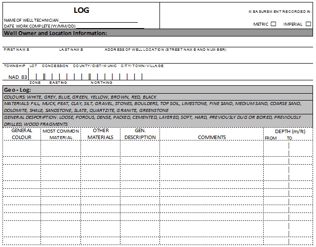
Figure 15-1 shows a sample log book entry
The upper left box states:
- Log
- Name of Well Technician
- Date work complete (YY/MM/DD)
The upper right box states:
- Measurement recorded in: (metric or imperial)
The Well Owner and Location Information box states:
- First Name
- Last Name
- Address of Well Location (Street Name and Number)
- Township
- Lot
- Concession
- Country/District/Municipality
- City/Town/Village
- UTM Coordinates: Zone, Easting, Northing
Geo – Log Box (located immediately below Well Owner and Location Information Box): (Colours: White, Greg, Blue, Green, Yellow, Brown, Red, Black)
(Materials: Fill, Muck, Peat, Clay, Silt, Gravel, Stones, Boulders, Top Soil, Limestone, Fine Sand, Medium Sand, Coarse Sand, Dolomite, Shale, Sandstone, Slate, Quartzite, Granite, Greenstone)
(General Description: Loose, Porous, Dense, Packed, Cemented, Layered, Soft, Hard, Previously Dug or Bored, Previously Drilled, Wood Fragments)
- Headings – General Colour, Most Common Material, Other Materials, General Description, Comments, Depth (metres/feet): From – To
- Rows 1 to 13 are blank
Map of Well Location Box (located on the left side below Geo – log box): (There are three examples of how to draw a map in rural areas, urban areas and lot/concession numbers not known)
- There is a plan view map showing the well located 4.1 kilometres north of highway 66 east, 300 metres east of Baseline Road, and 20.1 metres north of a building
Results of Well Yield Testing Box (located on the right side below Geo – log box):
- After test of well yield – clear and free of sand
- If pumping discontinued, give reason – none
- Pump intake set at – 15.24 metres
- Pumping rate - 26.5 litres per minute
- Duration of Pumping – 1 hour
- Final water level end of pumping – 11.3 metres
- Disinfected – yes
- Drawdown:
- static water level: 2.4 metres,
- 1 minute of pumping: 3.04 metres
- 2 minute of pumping: 3.7 metres
- 3 minute of pumping: 4.9 metres
- 4 minute of pumping: 5.5 metres
- 5 minute of pumping: 6.7 metres
- 10 minute of pumping: 10.9 metres
- 15 minute of pumping: 11.27 metres
- 20 minute of pumping: 11.27 metres
- 30 minute of pumping: 11.27 metres
- 40 minute of pumping: 11.27 metres
- 50 minute of pumping: 11.27 metres
- 60 minute of pumping: 11.27 metres
- Recovery:
- 1 minute of recovery: 11 metres
- 2 minute of recovery: 10.36 metres
- 3 minute of recovery: 8.5 metres
- 4 minute of recovery: 7.9 metres
- 5 minute of recovery: 7.01 metres
- 10 minute of recovery: 6.7 metres
- 15 minute of recovery: 5.5 metres
- 20 minute of recovery: 3.96 metres
- 30 minute of recovery: 3.04 metres
- 40 minute of recovery: 2.4 metres
- 50 minute of recovery: 2.4 metres
- 60 minute of recovery: 2.4 metres
Construction Record – Screen Box (located below Results of Well Yield Testing Box):
- Outside diameter – Not filled out
- Material – Not filled out
- Slot # - Not filled out
- Diameter (From – to) – Not filled out
Construction Record – Casing Box (located below Construction Record – Screen Box):
- Inside diameter – 15.88 centimetres
- Open hole or material – steel
- Wall thickness – 0.477 centimetres
- Depth – from 0 to 11 metres
- Lengths of casing brought to job site in metres – 6,6 6,10, 6, 6, 3
- Lengths of casing installed in well in metres – 6, 6
Water Details Box (located below Map of Well Location Box):
- Water found at Depth – 12.8 metres
- Kind of water – fresh
Hole Diameter Box (located below Map of Well Location Box and to the right of the Water Details Box):
- Depth – from 0 to 11 metres with a diameter of 2.54 centimetres
- Depth – from 11 to 16.76 metres with a diameter of 15.56 centimetres
Annular Space Box (located below the Water Details Box):
- Depth – from 0 to 11 metres
- Material – bentonite
- Number of bags placed - 3
Well Owner’s Information Package (located below the Hole Diameter Box):
- Yes
- Date Package Delivered – 05/07/21
Well Record Exemption
There are exemptions for the completion of a well record for certain types of activities that involve test holes and dewatering well. The circumstances when a well record is not necessary are described in this section.
A person who performs a “minor alteration” or installs a pump in a test hole or dewatering well is not required to complete and submit a well record, unless there is a damaged well tag. The physical structure of a test hole or dewatering well is not significantly altered when a person installs a pump or performs a “minor alteration”. In these cases, there is no major change to the structure of a test hole or dewatering well to be documented on a well record.
Reminder: For further information on when to complete a well record for a damaged well tag, see “Replacement of Damaged Well Tag and Well Record Completion” in the “Plainly Stated” section of this chapter and the “Broken, Defaced, Illegible or Unusable Well Tags” section in this chapter.
The person constructing the well is not required to complete a well record for the construction, including an alteration, of a new test hole or dewatering well, if the well is abandoned within 30 days of the completion of the well’s structural stage. Also, the person abandoning the well, often the well owner, is not required to complete a well record for the abandonment of a test hole or dewatering well if the well is abandoned within 30 days after the date on which its structural stage is complete.
The reporting requirements of the Wells Regulation capture the construction, alteration and abandonment of long term (>30 days) test holes and dewatering wells. For example, the Ministry expects a well record for a new test hole that will monitor the long term groundwater impact of a waste disposal site or for a dewatering well that will be pumping contaminated groundwater to contain a spill. Well records also have to be submitted for the abandonment of these wells in these circumstances.
Reminder: For further information on the terms “minor alteration”, “pump” and “well’s structural stage completion” see Chapter 2: Definitions & Clarification, Table 2-1.
Best Management Practice – Completing and Submitting a Well Record in Special Cases
There are cases where the person constructing the well is required to affix a well tag to the test hole or dewatering well, but is not required to complete a well record. In the following instances, a well record should be completed and submitted:
- The construction of a new individual cased test hole or dewatering well that is scheduled to be abandoned not later than 30 days of completion of its structural stage.
- When a well tag is required to be affixed in the course of installing a pump.
Also, the person abandoning the well should complete and submit a well record for the abandonment of an individual cased test hole or dewatering well that is abandoned not later than 30 days of completion of its structural stage.
The additional well records will help to:
- link and locate tagged wells in the field to well records,
- capture more information on wells, groundwater and geology for the Ministry’s water well database, and
- identify potential pathways for contamination.
Well Record Information
Unless exempt, a test hole or dewatering well will typically have multiple well records during its life. For example, a well could have a well record for construction, another if the well is altered and a third when it is abandoned.
There are 2 kinds of well records that may be completed and submitted for test holes and dewatering wells:
- Single Well Record – Used to report the construction or abandonment of one test hole or dewatering well.
- Well Record for Well Cluster – Used to report the construction or abandonment of a group of test holes or dewatering wells that meet the specific criteria outlined in the Wells Regulation (see the “Plainly Stated” section at the beginning of this chapter).
When to Complete a Well Record for a Single Well
The Wells Regulation - Unless otherwise exempt, the person constructing the well must complete and submit a separate well record for a single test hole or dewatering well for the following well construction activities:
- New well construction
- Making an alteration to a well other than a minor alteration or installing a pump. This includes a well that was part of a group of wells that was originally reported on one well record, also known as a well cluster
- Making a minor alteration to a well or installing a pump in or on a well where the well tag is broken, defaced, illegible or otherwise unusable
The Wells Regulation - Unless otherwise exempt, the person abandoning the well, often the well owner, must complete and submit a separate well record for the proper abandonment of a single test hole or dewatering well.
Reminder: See the “General Notes on Well Record Delivery” section in this chapter for further clarification on the term “person abandoning the well”. See Chapter 17: Abandonment: How to Plug & Seal Test Holes & Dewatering Wells for information on proper well abandonment.
Reminder: For further information on the terms “minor alteration”, “pump” and “well’s structural stage completion” see Chapter 2: Definitions & Clarification, Table 2-1. See the “Well Record Exemption” section in this chapter for further information on exemptions.
When the Option of Completing a Well Record for a Well Cluster Can Be Used
- “Well cluster”
- means a group of wells for which the person constructing the wells may complete one well record under subsection 16.4(1) of the Wells Regulation.
Reminder: See Chapter 2: Definitions & Clarifications, Table 2-1 for the term “well cluster” and the “Plainly Stated” section of this chapter for further clarification on the circumstances when a group of wells can be reported on one well record form for a “well cluster”.
The Wells Regulation: If the conditions found in the “Circumstances When Well Cluster Option Applies” part of the “Plainly Stated” section in this chapter are met, the person constructing the wells may choose to complete a well record form for a “well cluster” for the construction of multiple new test holes or dewatering wells.
The Wells Regulation: If the conditions found in the “Circumstances When Well Cluster Option for Abandonment Applies” part of the “Plainly Stated” section in this chapter are met, the person abandoning the well may choose to complete a well record form for a “well cluster” for the abandonment of test holes or dewatering wells that originally were part of a well cluster.
Reminder: A well record form for a “well cluster” is made up of three parts:
- a Well Record for Well Cluster form - Part 1 of 3
- a Well Record for Well Cluster - Part 2 of 3 Land Owners Consent and
- a Well Record for Well Cluster - Part 3 of 3 Detailed Drawing of All Well Locations
Best Management Practice – Using a Separate Well Record
A well record form for a “well cluster” provides limited information on each well in a group of wells compared to a separate well record for a single well. When a person has a choice of using a well record form for a “well cluster”, the person should complete a separate well record for each individual new test hole or dewatering well. In this circumstance, the person should also affix a well tag to each well and report the tag number on the corresponding well record. The use of a separate well record and well tag for each test hole or dewatering well will help report accurate information on a well for spill or complaint response and help in managing the groundwater resources.
Diagrams Showing How to Determine If a Test Hole or Dewatering is Part of a Well Cluster
Figure 15-2 to Figure 15-8 show plan view illustrations for test holes or dewatering wells that may, or may not, be considered as part of a well cluster. Explanations of how this was determined are also provided under the figures.
Reminder: Only test holes or dewatering wells can be part of a well cluster.
Reminder: All figures and diagrams are for illustrative purposes only and do not necessarily represent full compliance with other requirements found in the Wells Regulation. The illustrations and graphics may not depict every circumstance.
Reminder: The well record must be delivered to the well purchaser, each owner of the land (or property) and the Director in the time frames found in the “Construction - Delivery Requirement for Well Cluster” and “Abandonment - Delivery Requirement for Well Cluster” parts of the “Plainly Stated” section in this chapter. To be in compliance with the required time frames for well record submission, the multiple test holes or dewatering wells reported on a Well Record for Well Cluster must be constructed, or abandoned, within the time periods specified in the Wells Regulation.
Figure 15-2: Example of Wells on Adjacent Properties
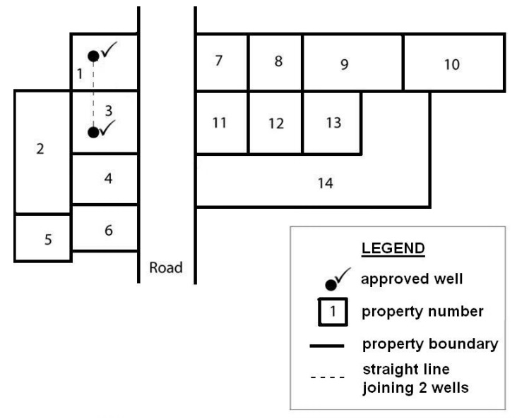
A straight line is drawn between a well on property 1 and a well on property 3. The straight line between the wells has determined that properties 1 and 3 are adjacent to one another. Therefore, all test holes or dewatering wells on properties 1 and 3 can be part of a well cluster as long as the conditions found in the “Circumstances When Well Cluster Option Applies” part of the “Plainly Stated” section in this chapter are met.
Reminder: The diagram above is not to scale and is for illustrative purposes for this chapter only.
Figure 15-3: Example of Wells on Properties with One Intervening Property and a Road
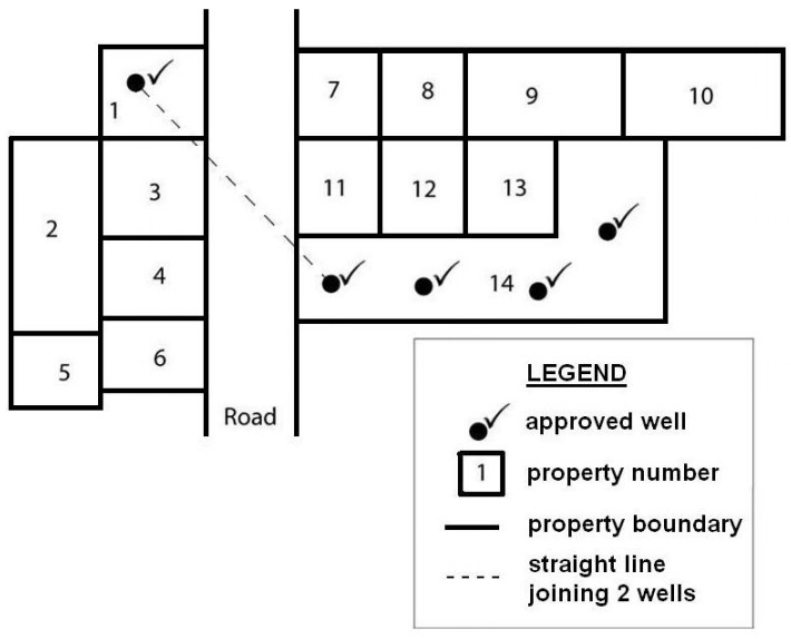
A straight line is drawn between a well on property 1 and a well on property 14. The straight line between the wells has determined that one (1) intervening property (property 3) is between the well on property 1 and a well on property 14. The road does not count as an intervening property in this situation. Therefore, the five (5) test holes or dewatering wells on properties 1 and 14 can be part of a well cluster as long as the conditions found in the “Circumstances When Well Cluster Option Applies” part of the “Plainly Stated” section in this chapter are met.
Reminder: The diagram above is not to scale and is for illustrative purposes for this chapter only.
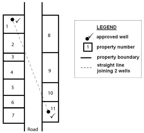
Figure 15-4: Example of Wells on Properties With Two or More Intervening Properties and a Road
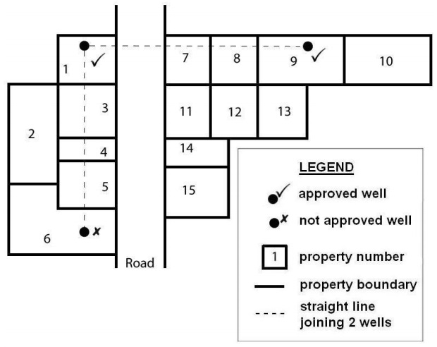
A straight line is drawn between a well on property 1 and a well on property 9. The straight line between the wells has determined that two (2) intervening properties (properties 7 and 8) are between the well on property 1 and the well on property 9. The road does not count as an intervening property in this situation. Therefore, the two (2) test holes or dewatering wells on properties 1 and 9 can be part of the well cluster as long as the conditions found in the “Circumstances When Well Cluster Option Applies” part of the “Plainly Stated” section in this chapter are met.
A straight line is drawn between a well on property 1 and a well on property 6. The straight line between the wells has determined that three (3) intervening properties (properties 3, 4 and 5) are between the well on property 1 and the well on property 6. If a straight line is drawn between the well on property 6 and the well on property 9, the line would also pass through 3 intervening properties. Therefore, the one test hole or dewatering well on property 6 cannot be part of the well cluster because the maximum number of intervening properties can only be one (1) or two (2) properties.
Reminder: The diagram above is not to scale and is for illustrative purposes for this chapter only.
Figure 15-5: Example of Wells on Properties Near a Road
A straight line is drawn between a well on property 1 and a well on property 11. Part of the straight line between the wells extends across a road. There are more properties on the left side of the road compared to the right side. Therefore, the right side of the road (i.e., the side with the fewest properties) is used to determine the number of intervening properties between the wells. In this case, property 8 is considered to be across the road from property 1. There are two (2) intervening properties between property 8 and the well on property 11. Therefore, the two (2) test holes or dewatering wells on properties 1 and 11 can be part of the well cluster as long as the conditions found in the “Circumstances When Well Cluster Option Applies” part of the “Plainly Stated” section in this chapter are met.
As an alternative, a straight line is drawn between the well on property 1 and the well on property 11. The straight line between the wells has determined that two (2) intervening properties (properties 2 and 10) are between the well on property 1 and the well on property 11. The road does not count as an intervening property in this situation. Therefore, the two (2) test holes or dewatering wells on properties 1 and 11 can be part of the well cluster as long as the conditions found in the “Circumstances When Well Cluster Option Applies” part of the “Plainly Stated” section in this chapter are met.
Reminder: The diagram above is not to scale and is for illustrative purposes for this chapter only.
Figure 15-6: Example of a Well on a Property and a Well on a Road
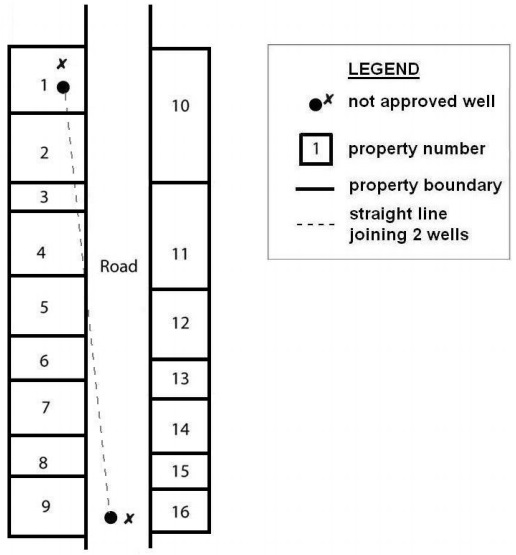
A straight line is drawn between the well on property 1 and the well on the road between properties 9 and 16. Part of the straight line is between the boundaries of a road. There are more properties on the left side of the road compared to the right side. Therefore, the right side of the road (i.e., the side with the fewest properties) is used to determine the number of intervening properties between wells. In this case, property 16 is considered to be beside the well on the road and property 10 is considered to be beside the well on property 1. There are five (5) intervening properties (properties 11 to 15) between property 10 and property 16. Therefore, the one test hole or dewatering well on property 1 and the other well on the road cannot be part of the well cluster because the maximum number of intervening properties can only be one (1) or two (2) properties.
Reminder: The diagram above is not to scale and is for illustrative purposes for this chapter only.
Figure 15-7: Second Example of a Well on a Property and a Well on a Road
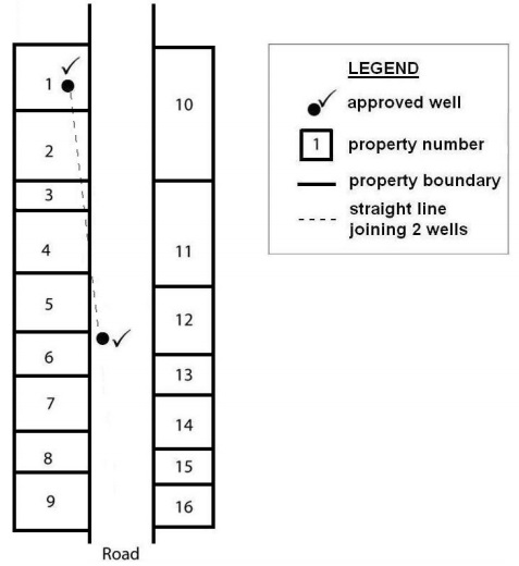
A straight line is drawn between the well on property 1 and the well on the road beside properties 6 and 12. Part of the straight line is between the boundaries of a road. There are more properties on the left side of the road compared to the right side. Therefore, the right side of the road (i.e., the side with the fewest properties) is used to determine the number of intervening properties between wells. In this case, property 12 is considered to be beside the well on the road and property 10 is considered to be beside the well on property 1. There is one (1) intervening property (property 11) between property 10 and property 12. Therefore, the one test hole or dewatering well on property 1 and the other well on the road can be part of the well cluster as long as the conditions found in the “Circumstances When Well Cluster Option Applies” part of the “Plainly Stated” section in this chapter are met.
Reminder: The diagram above is not to scale and is for illustrative purposes for this chapter only.
Figure 15-8: Example of Wells on a Road
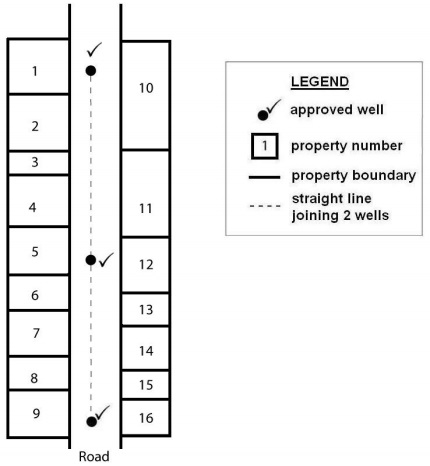
A straight line is drawn on the road from the upper well through the middle well and to the lower well. In the Figure 15-8 example, the road is owned by one person. An example of a person is a municipality. The straight line is within the boundaries of a road. The road is considered one property. Therefore, the three (3) test holes or dewatering wells on the road can be part of the well cluster as long as the conditions found in the “Circumstances When Well Cluster Option Applies” part of the “Plainly Stated” section in this chapter are met.
Reminder: The diagram above is not to scale and is for illustrative purposes for this chapter only.
Considerations When Completing a Well Record for a Single Well
A person who is required to complete a well record must follow the instructions on the well record. The instructions for completing a well record after construction or abandonment of a single well are found on the back of the well record form. The well record includes instructions on how to observe and report the formation’s texture (grain size), colour, hardness of the formations and other observations. See Figure 15-9 to Figure 15-21 for further information on completing the well record for a single well.
The person altering or abandoning an existing well must, as a minimum, complete the mandatory sections of the well record as stated in the instructions found on the back of the well record. The mandatory sections of the well record are not shaded.
It is not necessary to complete a well record when installing a pump or performing a minor alteration, unless the well tag is broken, defaced, illegible or otherwise unusable (see the “Broken, Defaced, Illegible or Unusable Well Tags,” section of this chapter).
There are also well tagging requirements that come into effect when altering a test hole or dewatering well in a well cluster (see the “Well Tags” section of this chapter).
When completing a well record for a single test hole or dewatering well, the person constructing the test hole or dewatering well must record the static water level that s/he is required to measure. The information must be recorded in the Results of Well Yield Testing section of the well record when completing a well record for a single well. For additional information on the requirement to measure the static water level, see Chapter 13: Water Level Measurements, Aquifer Testing & Discharge Water Handling.
Considerations When Completing a Well Record for a Well Cluster
Currently the well record form for a “well cluster” consists of three parts. The first part is called a Well Record for Well Cluster – Part 1 of 3. The second part is called Well Record for Well Cluster – Part 2 of 3 Land Owner Consent. The third part is called Well Record for Well Cluster – Part 3 of 3 Detailed Drawing of All Well Locations.
The instructions for completing the well record form for a “well cluster” are found on the front and back of the Well Record for Well Cluster – Part 1 of 3, on the front of the Well Record for Well Cluster – Part 2 of 3 Land Owner Consent and on the front of the Well Record for Well Cluster – Part 3 of 3 Detailed Drawing of All Well Locations.
The Wells Regulation: In addition to the requirements stated on the front and/or back of the three parts, the person who constructs a group of test holes or dewatering wells and completes a well record for a well cluster must:
- indicate on the well record, in a convenient, concise and comprehensive manner, which of the wells share common features, such as diameter, construction technique, casing, venting, pumps and method of abandonment,
- include on the well record a statement that all the required written consents, from each owner of land on which a well in the group is situated, have been given, and
- include on the well record a statement that the person constructing the well will promptly submit to the Director, on request, any additional information in the person’s custody or control related to any well in the well cluster that the person has constructed.
Details recorded on the Well Record for Well Cluster – Part 2 of 3 Land Owner Consent must include:
- Well numbers from the Well Cluster – Part 3 of 3 Detailed Drawing of All Well Locations
- Each property location description
- Each land owner’s name
- Signature of each land owner
- Date signed
The Well Record for Well Cluster – Part 3 of 3 Detailed Drawing of All Well Locations must:
- have a scale,
- have labels on all properties and show property boundaries,
- show and label all named roads,
- show the location and number of each well in the well cluster,
- provide Universal Transverse Mercator (UTM) coordinates beside each well, if space permits,
- display at least two separate distances from the well to other structures, roads or watercourses, and
- have a North arrow.
Reminder: The Wells Regulation allows the Ministry to require the person constructing or abandoning the test hole or dewatering well to follow the instructions on the well record form for a “well cluster”. Thus, these instructions are not specifically listed in the Wells Regulation.
A fully completed multiple page well record form for a “well cluster” with detailed map provides the well owner, regulators, well contractors and consultants with an accurate location of all wells and the wells’ general construction details.
Units of Measurement
The single well record form and well record form for a “well cluster” allow for the use of Imperial units or metric units. A check box, found at the top of the well record, allows for the selection of metric or Imperial units. The unit system chosen must be used consistently throughout the well record. If a measurement is being reported in metres, it must be reported to the nearest tenth of a metre (e.g., 20.3 m).
Completing The Well Record for a Single Well
Figure 15-9 to Figure 15-21 provides an explanation of how to complete a well record
Figure 15-9: Single Well Record - General Information
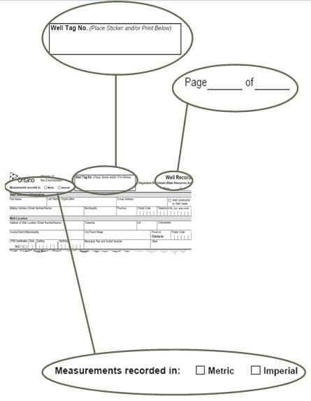
Well Tag Number
- This must match the well tag provided by the Ministry that is permanently affixed to the casing or another structure associated with the well. The well tag sticker provided in the well tag package should be used where a new well tag is affixed to the well to prevent errors in copying the number.
Page Number
- If more information needs to be recorded than can fit on one well record form, then an additional well record form must be filled out and labelled page 2.
- If there are two pages, the forms would read “Page 1 of 2” and “Page 2 of 2”, respectively
- Any additional pages must indicate the same well tag number
- All pages would constitute a single well record
Measurements
- The box for the chosen unit system must be checked
- Measurements must be recorded in the units specified in the well record sections
- The unit system chosen must be used consistently throughout the well record
Figure 15-10: Single Well Record - Well Owner Infomation
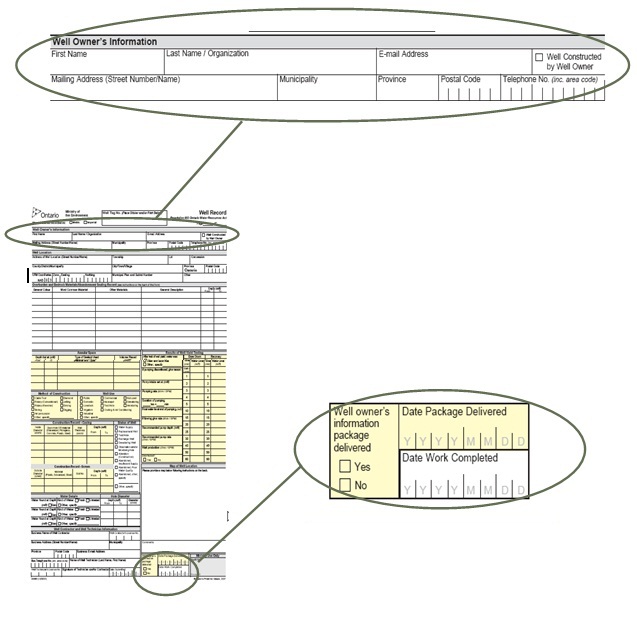
Well Owner Information
- All applicable sections must be completed
- This can be information on the owner of the land on which the well is located or the well purchaser
- If the well owner is an organization or company, the word “Organization” must be circled and the name of the entity must be printed in the “Last Name/Organization” field
Information Package
- This section must be completed
- As the information package is not required to be delivered for test holes or dewatering wells, “No” can be checked off
Figure 15-11: Single Well Record - Well Contractor and Well Technician
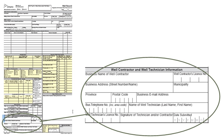
Well Contractor and Well Technician Information
- This box provides information about the individual and company who constructed the well and must be fully completed by the person constructing the well except for the following situations:
- If the person who constructed the well is an exempted professional who is permitted to construct wells without a licence (see Chapter 4: Test Hole & Dewatering Well Construction Licences: Obtaining, Maintaining & Exemptions), the person must record his/her name in the “Name of Well Technician” box, sign the “Signature of Technician” and provide his/her company’s particulars
- If the test hole or dewatering well was constructed by the owner of the land, a member of the person’s household or a person working without compensation for the owner of the land, the person constructing the well must record his/her name in the “Name of Well Technician” box and sign in the “Signature of Technician and/or Contractor” box. The words “Well Technician” and “Contractor” should be crossed out and the changes initialled
- If the test hole or dewatering well was abandoned, information about the person who works at the well abandonment may be recorded in this section
Figure 15-12: SingleWell Record - Well Location
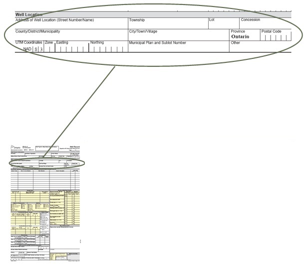
Well Location
-
It is important to accurately record the location the well. Inaccurate location information on the well record can lead to problems locating the well in the field. Location information includes the following:
- Street number/name, city/town/village must be provided if available
- Original geographic township, concession and lot must be reported if the well is located in an area where such information exists
- Fire locator number may also be recorded in the “Other” box
- UTM Coordinates must be recorded using a GPS unit
- Municipal plan and sublot numbers may be provided if available
- Current county or district/amalgamated municipality or township, if reported, should be entered under “County/District/Municipality.” For example, in the County of Frontenac/Township of South Frontenac, the Township of South Frontenac is the amalgamated township. If the townships were amalgamated, the old and new township names should be included, if known
Figure 15-13: Single Well Record - Map of Single Well Location
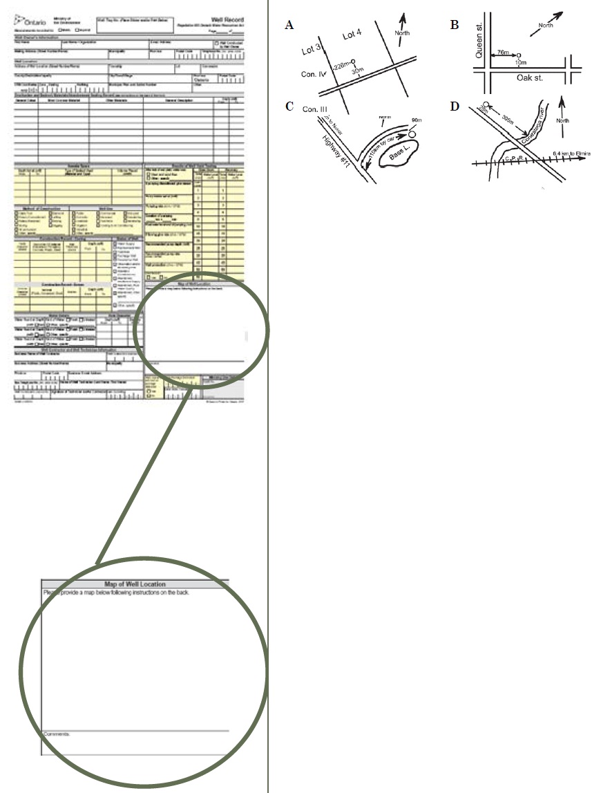
Map of Well Location
- A map showing all property boundaries must be provided. At least two measurements sufficient to locate the well in relation to fixed points must be provided. For example:
- In rural areas, one distance should be taken from a road and other from either a road or a township lot line (example A, below)
- In a village, town or city, both distances should be taken from named streets (example B)
- In areas where it is difficult to obtain lot and concession numbers, sufficient information should be supplied in the diagram so that the well can be related to a known unit such as a main highway, railway, or municipality (examples C and D)
- Detailed drawings can be provided as attachments on paper no larger than the size of the well record (8.5 inches by 14 inches)
- A North arrow must be included on the diagram.
- The “Comment” box may be used to record any additional information such as the elevation of the well. It is also an appropriate location to state whether or not hydrofracturing or blasting was done at the time of construction (see the BMP on this page)
- The “Comment” box is also an appropriate place to reference the original well tag when a well tag is replaced and original well record number for an alteration
- It is important to review the directions given on the back of the well record
Best Management Practice – Compiling Details about Hydrofracturing or Blasting Techniques
If hydrofacturing or blasting techniques were used, the person completing the well record should provide details on a separate sheet. The sheet should be attached to the well record and copies of the attachment should be included with each copy of the well record.
Figure 15-14: Single Well Record - Overburden and Bedrock Materials/ Abandonment Sealing Record
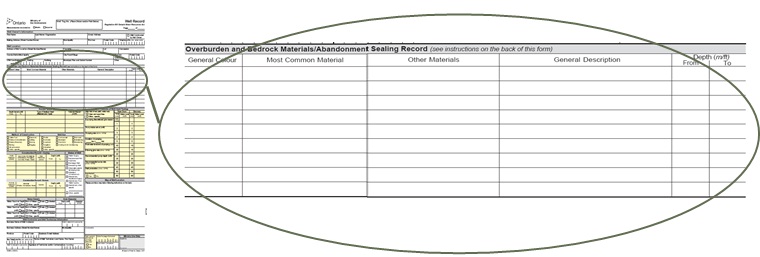
Overburden and Bedrock Materials/ Abandonment Sealing Record
- If a person is plugging and sealing a well, the abandonment details must be recorded in this section. The type of abandonment barrier (sealant) used must be indicated in the “General Description” column and the depth of sealant must be indicated in the “Depth” column
-
If a person is constructing a well:
- For each formation encountered during construction, words chosen from the lists provided on the back of the well record that best describe the formation on the basis of general colour, most common material, other materials and general description of the formation must be used
- Instructions are found on the back of the well record and shown below
General Colours:
- White
- Grey
- Blue
- Green
- Yellow
- Brown
- Red
- Black
Materials:
- Fill
- Muck
- Peat
- Clay
- Silt
- Gravel
- Stones
- Boulders
- Top Soil
- Limestone
- Fine Sand
- Medium Sand
- Coarse Sand
- Dolomite
- Shale
- Sandstone
- Slate
- Quartzite
- Granite
- Greenstone
General Descriptions:
- Loose
- Porous
- Dense
- Packed
- Cemented
- Layered
- Soft
- Hard
- Previously Dug or Bored
- Previously Drilled
- Wood Fragments
Clay: Composed of very fine particles. Forms dense hard lumps or clods when dry and a very elastic putty-like mass when wet. It can be rolled between fingers to form a long, flexible ribbon.
Silt: Grain size, midway between sand and clay. It may form clods which, when broken, feel soft and floury. When moist, it will form a cast that can be handled freely without breaking. Rolled between thumb and finger, it will not “ribbon” but will give a broken appearance.
Sand: Grain are loose and granular and may be seen and felt readily. Squeezed in the hand when dry, it falls apart when the pressure is released. Squeezed when moist, it will form a cast that will crumble when touched. Should be listed as fine, medium or coarse.
Gravel: Rock fragments greater than 0.3 cm in diameter
- An example of a completed section is provided below and found on the back of the well record:
Example of a Completed Section General Colours Most Common Material Other Materials General Descriptions Depth From Depth To Brown Top Soil n/a n/a 0 0.6 Grey Coarse Sand Gravel, Silt Loose, Wood Fragments 0.6 13.0 Blue Clay Silt, Stones Dense 13.0 25.0 Brown Fine Sand Clay n/a 25.0 31.0 Grey Limestone n/a Porous, Hard 31.0 34.0
Figure 15-15: Single Well Record - Well Use
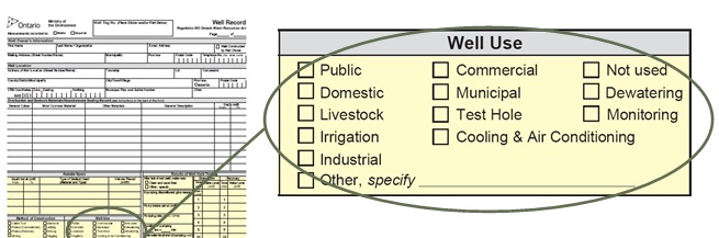
Well Use
- Well use
- means the intended purpose at the time of construction
- For the purposes of test holes and dewatering wells the following will apply:
- Test Hole – a well that is made to test or to obtain information in respect of groundwater or an aquifer and is not intended as a source of water for agriculture or human consumption
- Dewatering – a well that is not used or intended for use as a source of water for agriculture or human consumption and that is made to lower or control the level of groundwater in the area of the well, or to remove materials that may be in the groundwater
- Monitoring – a well that is made to test or to obtain information in respect of groundwater or an aquifer and is not intended as a source of water for agriculture or human consumption
- Other – e.g., communal such as water supply that serves a small rural sub-division
- In the situation where a test hole or dewatering well for a sub-division is then going to be used as a domestic water supply, all boxes that apply should be checked (original and future purposes)
- For the purposes of the Wells Regulation and the well record completion, “Test Hole” and “Monitoring” are synonymous
Figure 15-16: Single Well Record - Method of Well Construction & Status of Well
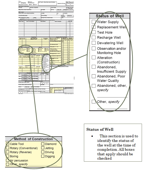
Status of Well
- This section is used to identify the status of the well at the time of completion. All boxes that apply should be checked
Method of Construction
- The construction method used is identified by checking the appropriate box or boxes if more than one system is used (e.g., rotary conventional and air percussion). If the method used is not part of the list, the “Other, specify” box must be checked and the method must be described (e.g.,sonic or direct push)
Figure 15-17: Single Well Record - Construction Record - Casing
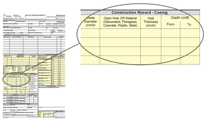
Construction Record - Casing
- Material means type of manufactured material used to make the casing
- An interval without casing must be reported as “open hole”
- Wall thickness means minimum or nominal wall thickness
- A new line should be filled in for every change in casing (e.g., material, inside diameter or wall thickness) or open hole diameter
- All depths must be expressed from the ground surface at the time of construction. The amount of casing above the ground surface should be expressed with “+”. For example, a contractor installs casing +0.6 m above the ground surface and extends the casing to 7 m below the ground surface
- Joint and packer depths from ground surface should be recorded (see the best management practice below)
Best Management Practice – Recording Joint and Packer Locations
Casing joint and packer locations (depths) from ground surface should be recorded in the “Construction Record – Casing” box of the well record.
Figure 15-18: Single Well Record - Construction Record - Well Screen and Hole Diameter
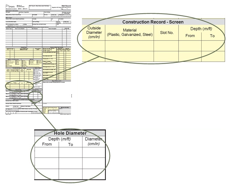
Construction Record - Screen
- Material can also include pre-packed well screens and unsealed concrete tiles or other material installed in a well to filter out particulate matter
- Slot number as provided by the manufacturer must be recorded
- Depth includes top of riser pipe, if applicable
- All depths must be expressed from the ground surface at the time of construction
Hole Diameter
- The diameter and depth of the hole must be recorded using the measurement unit system chosen at the top of the well record (metric or Imperial)
- The depth of the hole relative to the ground surface must be recorded
Figure 15-19: Single Well Record - Annular Space
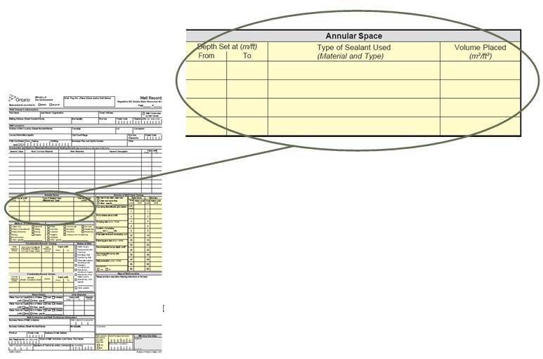
Annular Space
- “Depth set at” relative to the ground surface must be recorded
- The type of suitable sealant installed in the annular space must be recorded
- “Depth set at” and “volume placed” in the measurement units indicated at the top of the well record (metric or Imperial) must be recorded
- The volumes of sealant placed must be shown as either m3 or ft3
- “Volume placed” (see Chapter 7: Annular Space & Sealing, Calculating Amount of Material Required section) must be calculated
- Type of Sealant Used:
- “Material” means sodium bentonite, cement, concrete and other suitable sealants
- “Type” means trademark name of the product
Best Management Practice – Recording all Material Installed in Annular Space
Within the annular space box, the person constructing the well should record where any clean washed sand or gravel has been installed in the well’s annular space (e.g., around well screen).
Figure 15-20: Single Well Record - Water Details
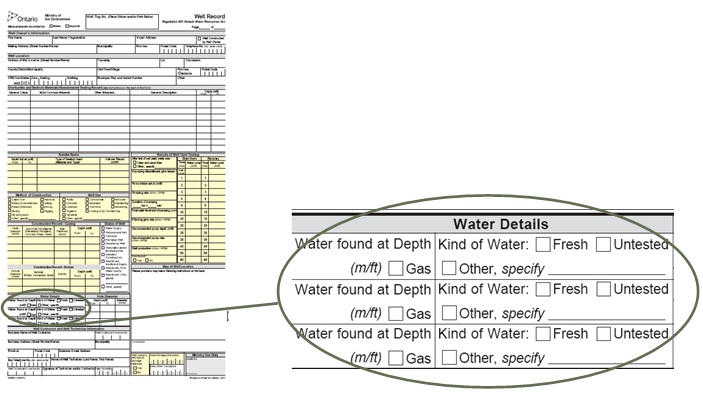
Water Details
- The distance from the ground surface to the water bearing formation(s), or horizon(s), where water is found must be recorded. Also, if naturally occurring or other gas is found then it must be recorded
- The same measurement unit system chosen at the top of the well record (metric or Imperial) must be used consistently
- The correct box for the type of water found must be checked:
- “Fresh water” means that there are no taste, odour or colour issues with the well water in the field (Field testing equipment should be used instead of tasting well water to avoid drinking potentially contaminated or non-potable water)
- “Other” could include mineralized water (see definition in Chapter 2: Definitions & Clarifications, Table 2-1)
- If gas is encountered, the Ministry of the Environment and Climate Change must be contacted (see “Notifications” section in this chapter)
Figure 15-21: Single Well Record - Well Yield
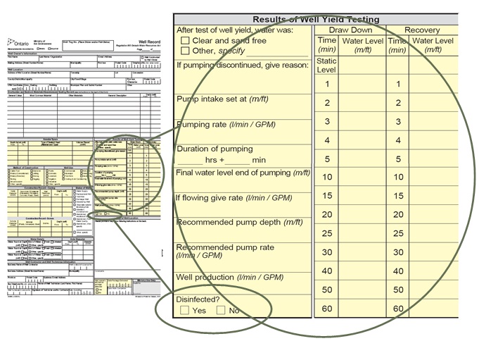
Disinfected
- Typically will be “no” as this is not required for test holes and dewatering wells
Results of Well Yield Testing (Static Level Box)
- When a static water level measurement is required, it must be recorded in the “static level” box in this section
- See Chapter 13: Water Level Measurements, Aquifer Testing & Discharge Water Handling for information on when the static water level is to be measured in a test hole or dewatering well
- Other information is not required to be completed in “Results of Well Yield Testing” section for a test hole or dewatering well
Completing a Well Record Form for a "Well Cluster"
Figure 15-22 to Figure 15-35 provide an explanation of how to complete a Well Record for Well Cluster Part 1 of 3. This process involves accurately completing the Well Record for Well Cluster. A completed well record form for “well cluster” also includes a Well Record for Well Cluster – Part 2 of 3 Land Owners Consent (see Figure 15-36) and a Well Record for Well Cluster – Part 3 of 3 Detailed Drawing of All Well Locations (see Figure 15-37).
Figure 15-22 Well Record for Well Cluster - Measurements
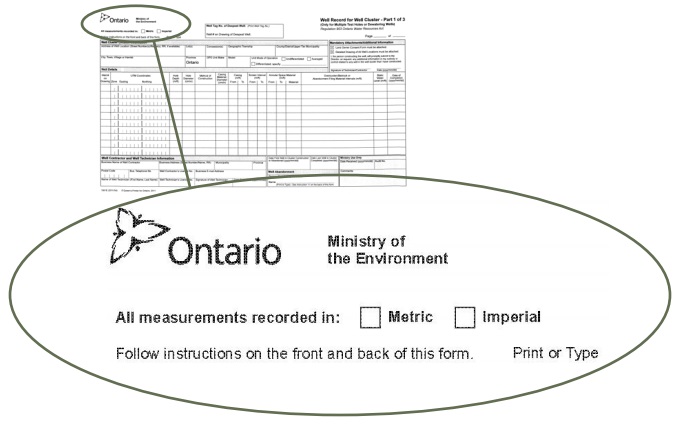
Measurements
- The box for the chosen unit system must be checked
- Measurements must be recorded in the units specified in the Well Record for Well Cluster sections
- The unit system chosen must be used consistently throughout the Well Record for Well Cluster
Figure 15-23: Well Record for Well Cluster - Well Tag and Page Numbering
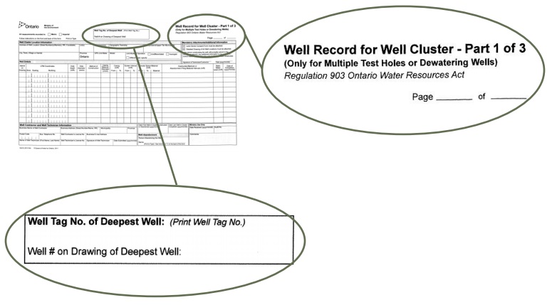
Well Tag Number
- This must match the well tag provided by the Ministry that is permanently affixed to the casing of the deepest well in the Well Cluster or another structure associated with that well. The well tag sticker provided in the well tag package should be used where a new well tag is affixed to the well to prevent errors in copying the number
- Also, the person must clearly identify the well with the well tag on the Well Record for Well Cluster - Part 3 of 3 - Detailed Drawing of All Well Locations
- If a well tag is affixed to the well(s) being abandoned, the person abandoning the well must record the well tag number for the well abandonment
- If a tag is not affixed to the well(s) being abandoned, the person abandoning the well(s) should record the well tag number for the original cluster
Page Number
- If more information needs to be recorded than can fit on one Well Record for Well Cluster Part 1 of 3, then an additional Well Record for Well Cluster - Part 1 of 3 page must be filled out and labelled page 2
- If there are two pages, the pages would read “Page 1 of 2” and “Page 2 of 2”, respectively
- Any additional pages must indicate the same well tag number and the Well Number of the deepest well in the Well cluster
- These pages plus the Well Record for Well Cluster – Part 2 of 3 Land Owner Consent and Well Record for Well Cluster - Part 3 of 3 Detailed Drawing of All Well Locations constitute a Well Record form for a Well Cluster
Figure 15-24: Well Record for Well Cluster - Location, Address
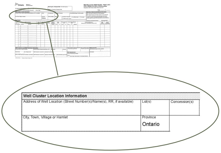
Well Cluster Location Information - Address
- Where available, the person completing the form must record the street name(s), street number(s) and/or rural route numbers for all properties in the well cluster
- City/town/village must be provided
- If there is not enough room refer persons to the Land Owner Consent form for all well location information
Well Cluster Location Information – Lot(s) and Concession(s)
- Where available, the person completing the form must record all municipal lots and concessions for all properties in the well cluster
- These numbers are more commonly used in rural areas
Figure 15-25: Well Record for Well Cluster - Location, Township
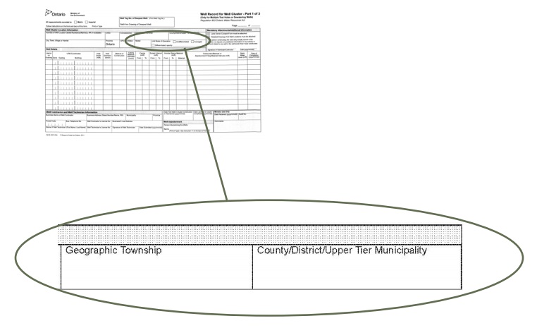
Well Cluster Location Information – Geographic Township
- Where available, the person completing the form must record the former Township for an area that has gone through amalgamation, renaming or re-organization
- For example, the “Township of Hawley” became part of the “Greater City of Sudbury”. If a person is constructing test holes or dewatering wells in this area, the person must record “Hawley” in the Geographic Township box
Well Cluster Location Information – County or District/Upper Tier Municipality
- The person completing the page must record the County or District and, if applicable, the Upper Tier Municipality
- For example, a number of townships amalgamated to form the Township of Central Frontenac in the County of Frontenac. If a person is constructing or abandoning test holes or dewatering wells in this area, the person must record “Frontenac County/Central Frontenac Township” in this box
Figure 15-26: Well Record for Well Cluster - Mandatory Attachments and Additional Information
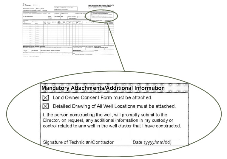
Mandatory Attachments
- Boxes are already checked on the form to remind the person constructing or abandoning the test holes or dewatering wells that s/he must attach a Well Record for Well Cluster - Part 2 of 3 Land Owner Consent and a Well Record for Well Cluster - Part 3of 3 Detailed Drawing of All Well Locations form in order for this record to comply with the Wells Regulation
- The person constructing or abandoning the test holes or dewatering wells must sign and date (year/month/day) the Well Record for Well Cluster form in this box
Figure 15-27: Well Record for Well Cluster - Well Number and UTM Coordinates
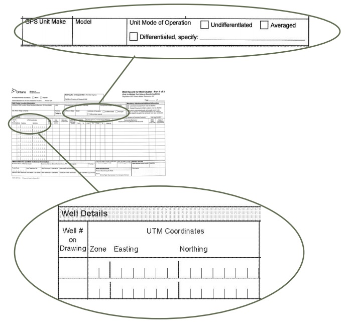
GPS
- The person must record the GPS unit, model and mode of operation that is used to record the Universal Transverse Mercator (UTM) coordinates of each well
- When applicable, the person must specify any differentiated unit mode of operation
Well No. on Drawing
- To help identify the well, the person constructing or abandoning the test hole or dewatering well must record a Well Number of his/her choosing for each test hole or dewatering well in the well cluster
- This number must correspond to the Well Number used on the Detailed Drawing and also on the Land Owner Consent form
UTM Coordinates
- The person must record the Universal Transverse Mercator (UTM) reading for each test hole or dewatering well in the well cluster
- The UTM coordinates must correspond to the reading the person obtains from his/her GPS unit in the field for each test hole or dewatering well
- If space permits, the UTM Coordinates must also be recorded beside the corresponding Well Number on the Detailed Drawing
Figure 15-28: Well Record for Well Cluster - Hole Diameter
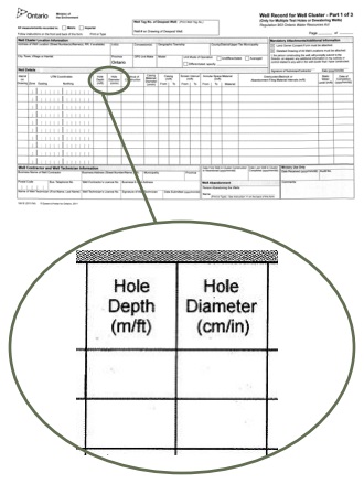
Hole Depth
- The person must record the depth of each test hole or dewatering well that is being constructed or abandoned using the measurement unit system chosen
- If the unit system is metric, the measurement must be recorded in metres. If the unit system is Imperial, the measurement must be recorded in feet
- The depth is the distance from the ground surface at the time of construction or abandonment of the well to the bottom of the well
Hole Diameter
- The person constructing or abandoning a well must record the diameter of each test hole or dewatering well using either metric or Imperial units as indicated in the check box at the top of the page
- If the unit system is metric, the measurement must be recorded in centimetres. If the unit system is Imperial, the measurement must be recorded in inches
- If the diameter changes over the depth of the hole, the depth followed by the diameter must be recorded
- If more space is necessary, the person can use the row immediately below the initial row that is being filled
- For example, if the first 6 metres of the hole has a diameter of 25.4 centimetres and the next 6 to 20 metres below the ground surface has a diameter of 15.9 centimetres, the person can record “0-6 m:25.4 cm” on the first row and then the person can record 6-20 m:15.9 cm on the next row immediately below.
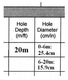
Figure 15-29: Well Record for Well Cluster - Construction Method and Casing
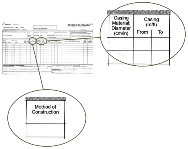
Method of Construction
- The person constructing the well must record the method of construction for each test hole or dewatering well that is being constructed
- Some construction methods used are: rotary conventional, rotary (air), rotary (water), rotary (mud), dual rotary, air percussion, sonic drilling, direct push, augering, boring, digging, driving, jetting, diamond drilling or cable tool
Casing Material; Diameter and Depth
- The person constructing the well must record the type of casing installed in the well, the outside diameter of the casing and depth of casing
- If the unit system is metric, the person must record the measurement for length in metres and for diameter in centimetres. If the unit system is Imperial, the person must record the measurement for length in feet and diameter in inches
- If more space is necessary, the person can use the row immediately below the initial row that is being filled.
- For example, the person installed a steel casing with an outside casing diameter of 16.0 centimetres in the upper 6 metres of the hole. A plastic casing with an outside diameter of 10.0 centimetres is installed within and below the larger casing from 5.5 to 20 metres below the ground surface. The person can record the casings on the form as shown below.
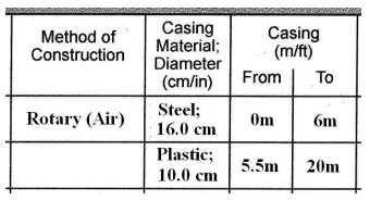
Figure 15-30: Well Record for Well Cluster - Well Screen and Annular Space
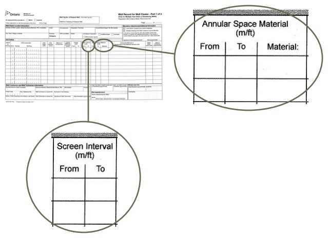
Well Screen Interval
- The person constructing the well must record the location of well screen interval if present
- If the unit system is metric, the person must record the measurement for length in metres. If the unit system is Imperial, the person must record the measurement for length in feet
Annular Space Material
- The person constructing the well must record the type and depth of the material placed in the annular space of each test hole and dewatering well, if present,
- If the unit system is metric, the person must record the measurement for length in metres. If the unit system is Imperial, the person must record the measurement for length in feet
- If more space is necessary, the person can use the row immediately below the initial row that is being filled
- For example, the person placed sand material in the annular space around a well screen and casing from 15 to 20 metres below the ground surface. The person also placed a bentonite slurry suitable sealant in the annular space of the same well from ground surface to 15 metres below ground surface. The person can record the annular space filling record as shown below.
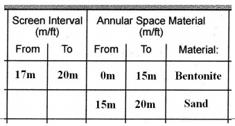
Figure 15-31: Well Record for Well Cluster - Overburden/Bedrock or Abandonment Filling Materials Intervals
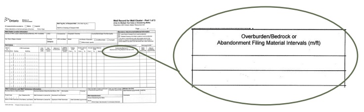
Overburden/Bedrock or Abandonment Filling Materials Intervals
- For the construction of each test hole, the person constructing the well must record the type and interval of overburden or bedrock materials
- If the unit system is metric, the person must record the measurement for length in metres. If the unit system is imperial, the person must record the measurement for length in feet
- If more space is necessary, the person can use the row immediately below the initial row that is being filled
- For each formation encountered during construction, the person can use the short forms for some common materials that are listed on the back of the form These include Basalt: BSLT; Dolomite: DLMT; Gneiss: GNIS; Granite: GRNT; Gravel: GRVL; Gypsum: GYPS; Limestone: LMSN; Marble: MRBL; Sandstone: SNDS
- As an example, a 40 metres deep test hole could be recorded as 0-3.5 m sand; 3.5-4 m clay; 4-40 m limestone
- If multiple test holes and dewatering wells that were originally part of a well cluster are being abandoned, then the person abandoning the well, often the well owner, must record the plugging and sealing details of each well in this section
- The person must record the type of abandonment barrier or fill material used and record the interval where the material was placed in the well
- If more space is necessary, the person can use the row immediately below the initial row that is being filled
- As an example, the abandonment of a 40 metres deep test hole could be recorded as 0-1.5 m silt; 1.5-2.0 m bentonite chips; 2.0-35.0 m bentonite slurry; 35.0-40.0 m gravel
- If the plugging and sealing of multiple test holes or dewatering wells that are part of a well cluster is occurring immediately due to the construction of the new wells being discontinued, then a well record is not required to be completed under the Wells Regulation. If the person wishes to complete a well record form for this, then the person should complete 2 Well Record for Well Cluster –Part 1 of 3 pages. The first page (page 1 of 2) is for the construction and the second form (page 2 of 2) is for the plugging and sealing of the well
Figure 15-32: Well Record for Well Cluster - Static Water Level, Date of Completion and Ministry Audit Number
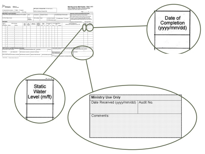
Static Water Level
- The person constructing the well must record the static water level from the original ground surface at the time of well construction
- The static water level is not required to be recorded for a well abandonment
- If the unit system is metric, the person must record the measurement for length in metres. If the unit system is Imperial, the person must record the measurement for length in feet
Date of Completion
- If the new well is being constructed, the person constructing the well must record the year/month/day that corresponds to the date on which the well’s structural stage is complete (when the well is ready to be put into operation but for the installation of a pump)
- If the well is being abandoned, the person abandoning the well, often the well owner, must record the year/month/day that corresponds to the date when the well was plugged and sealed
Ministry Audit Number
- The audit number is assigned by the Ministry
- The person constructing or abandoning the wells must record the audit number(s) on the Well Record for Well Cluster – Page 2 of 3 Land Owner Consent (see Figure 15-36)
Figure 15-33: Well Record for Well Cluster - Well Contractor and Well Technician
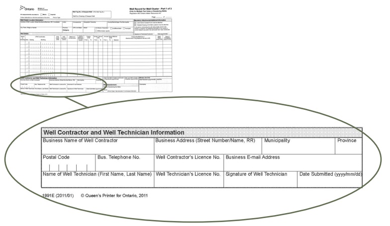
Well Contractor and Well Technician Information
- This box provides information about the individual and company who constructed the wells and must be fully completed by the person constructing the wells except for the following situations
- If the person who constructed the wells is an exempted professional who is permitted to construct wells without a licence (see Chapter 4: Test Hole & Dewatering Well Construction Licences: Obtaining, Maintaining & Exemptions), the person must record his/her name in the “Name of Well Technician” box, sign the “Signature of Technician” and provide his/her company’s particulars. The exempted professional should record their registration number or licence number in the “Well Technician’s Licence No.” box. The words “Well Technician” should be crossed out and the changes initialled,
- If the test holes or dewatering wells were constructed by the owner of the land, a member of the person’s household or a person working without compensation for the owner of the land, the person constructing the wells must record his/her name in the “Name of Well Technician” box and sign in the “Signature of Technician” box. The words “Well Technician” should be crossed out and the changes initialled,
- If the test holes or dewatering wells were abandoned, information about the person who works at the well abandonment may be recorded in this section
Figure 15-34: Well Record for Well Cluster - Date of First and Last Well
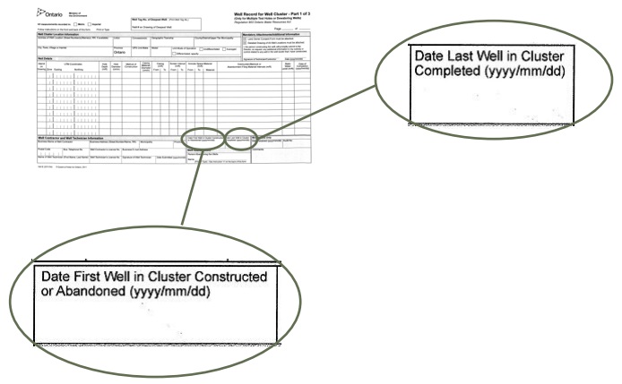
Date of First Well in Cluster Constructed or Abandoned
- The person constructing wells in a well cluster must record the year/month/day that corresponds to the commencement of well construction for the first well in a well cluster (or, where applicable, the first well in a particular phase of well construction)
- If the wells which are part of a well cluster are being abandoned, the person abandoning the well, often the well owner, must record the year/month/day that the first well in the Well Cluster was plugged and sealed
Date of Last Well in Cluster
- The person constructing wells in a well cluster must record the year/month/day that corresponds to the date of completion of the last well in a well cluster (or, where applicable, the last well in a particular phase of well construction)
- If the wells which are part of a well cluster are being abandoned, the person abandoning the well, often the well owner, must record the year/month/day that the last well in the well cluster was plugged and sealed
- The well record must be delivered to the well purchaser, each owner of the land and the Director in the time frames found in the “Construction - Delivery Requirement for Well Cluster” and “Abandonment - Delivery Requirement for Well Cluster” parts of the “Plainly Stated” section in this chapter. To be in compliance with the required time frames for well record submission, the multiple test holes or dewatering wells reported on a Well Record for Well Cluster form must be constructed, or abandoned, within the time periods specified in the Wells Regulation
Figure 15-35: Well Record for Well Cluster - Person Abandoning the Well
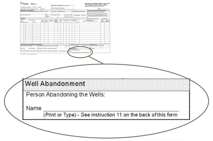
Person Abandoning the Well
- This box provides the name of the person abandoning the well if test holes or dewatering wells that were originally part of a Well Cluster are now being abandoned (plugged and sealed)
- In most cases, the person abandoning the well is the well owner
- When test holes or dewatering wells are being abandoned, the person abandoning the well is responsible for the completion of this form, including recording the appropriate name in this box, and proper well record submission
- A well technician (or other person who works at the abandonment of the well) can assist the person abandoning the well in completing and submitting this form
Figure 15-36: Well Record for Well Cluster - Land Owner Consent Form
A Well Record for Well Cluster – Part 2 of 3 Land Owner Consent (shown below) must be attached to the Well Cluster for Well Record – Part 1of 3. Details recorded on the Well Record for Well Cluster – Part 2 of 3 Land Owner Consent must include: the well number from the Well Record for Well Cluster – Part 3 of 3 Detailed Drawing of All Well Locations, the property location description, the land owner’s name, the signature of the land owner and the date signed. The well tag number and audit number must match the tag and audit number(s) on the Well Record for Well Cluster Part 1-3.
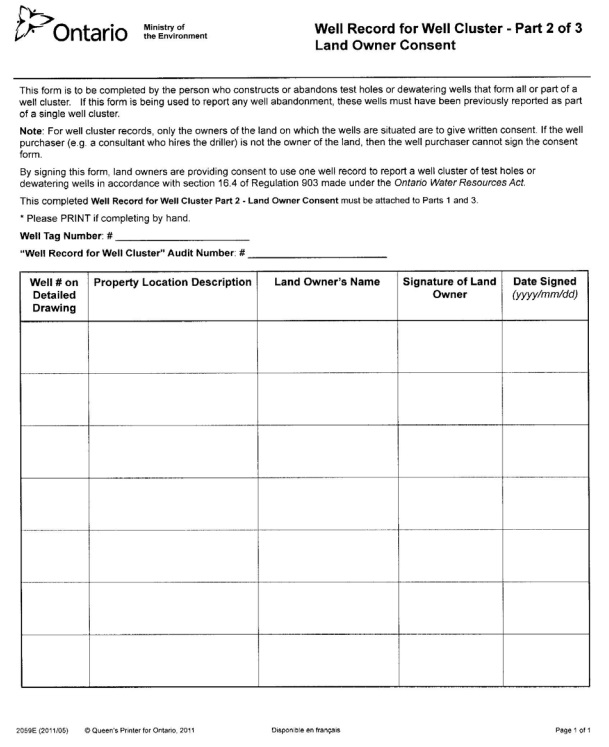
Figure 15-37: Well Record for Well Cluster - Detailed Drawing
A Well Cluster for Well Record – Part 3 of 3 Detailed Drawing of All Well Locations (shown below) must be attached to the Well Cluster for Well Record Part 1 of 3. The Well Cluster for Well Record – Part 3 of 3 Detailed Drawing of All Well Locations must include all property boundaries, an arrow indicating the North direction, all named roads and sufficient measurements to locate all wells in the cluster in relation to fixed points. The drawing must show the location of each well and each well must be numbered on the drawing. The well tag number should appear beside the well with a well tag. UTM coordinates should appear beside each well, if space permits. The Well Number on the drawing must correspond to the Well Number on the Well Cluster for Well Record – Part 2 of 3 Land Owner Consent. Additional comments on wells can also be included on the drawing.
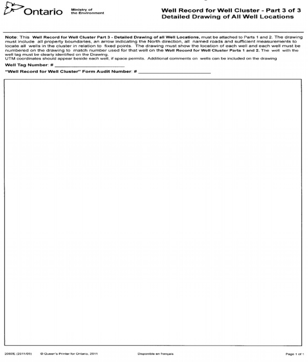
Well Record Delivery
New Well Construction - Single Well Record Delivery
The Wells Regulation - A copy of the completed well record must be delivered by the person constructing the well to the well purchaser and land owner within 14 days after the date on which the well’s structural stage is complete.
The Wells Regulation - A copy of the completed well record must be forwarded by the person constructing the well to the Ministry at the Wells Help Desk, Ministry of the Environment and Climate Change, 125 Resources Road, Toronto Ontario M9P 3V6 within 30 days after the date on which the well’s structural stage is complete.
The Wells Regulation - A completed well record must be kept by the person constructing the well for at least two years.
Alterations - Single Well Record Delivery
The Wells Regulation - A copy of the completed well record must be delivered by the person constructing (altering) the well to the well purchaser and land owner within 14 days after the date on which the well’s structural stage is complete
The Wells Regulation - A copy of the completed well record must be forwarded by the person constructing (altering) the well to the Ministry at the Wells Help Desk, Ministry of the Environment and Climate Change, 125 Resources Road, Toronto Ontario M9P 3V6 within 30 days after the date on which the well’s structural stage is complete.
The Wells Regulation - A completed well record must be kept by the person constructing the well for at least two years.
Reminder: Generally, a well record is not required to be completed for a minor alteration or the installation of a pump. If a well tag is broken, defaced, illegible or otherwise unusable, however, a well record is required to be completed with respect to the required replacement of the well tag, even during a minor alteration. See the “Broken, Defaced, Illegible or Unusable Well Tag” section later in this chapter for further information on the well tag replacement and the well record completion and submission requirements in this case.
Reminder: Further information on the “well’s structural stage completion”, “minor alteration” and “pump” can be found in Chapter 2: Definitions & Clarifications, Table 2-1. The term minor alteration is also discussed in the “Well Tags” section on page 69 of this chapter.
Abandonment - Single Well Record Delivery
The Wells Regulation - On completion of the abandonment of a test hole or dewatering well, the person abandoning the well, often the well owner, must:
- within 14 days after the date on which the well construction equipment is removed from the site, deliver a copy of the well record to the owner of the land on which the well is situated; and
- within 30 days after the date on which the well construction equipment is removed from the site, forward a copy of the well record and any well tag that was removed from the well, to the Director.
Reminder: See Chapter 17: Abandonment: How to Plug & Seal Test Holes & Dewatering Wells for information on proper well abandonment.
New Well Construction - Delivery of Well Record for Well Cluster
The Wells Regulation - A person constructing new test holes or dewatering wells who completes one well record for a well cluster must deliver a copy of the well record for the well cluster to the well purchaser and each owner of land on which a well in the well cluster is situated within 60 days after the commencement of construction:
- of the first test hole or dewatering well or,
- of the first test hole or dewatering well in the relevant phase of construction, if the wells are being constructed in phases.
The Wells Regulation - A completed well record for a well cluster must be forwarded to the Ministry at the Well Help Desk, Ministry of the Environment, 125 Resources Road, Toronto Ontario M9P 3V6 within 75 days after the commencement of construction:
- of the first test hole or dewatering well or,
- of the first test hole or dewatering well in the relevant phase of construction, if the wells are being constructed in phases.
The Wells Regulation - A completed well record for a well cluster must be kept by the person constructing the test hole or dewatering well for at least two years.
Reminder: A well record for a well cluster consists of a Well Record for Well Cluster – Part 1 of 3, a Well Record for Well Cluster – Part 2of 3 Land Owners Consent, and a Well Record for Well Cluster – Part 3 of 3 Detailed Drawing of All Well Locations.
Best Management Practice – Keeping the Well Record
Any well record for construction, alteration or abandonment should be kept longer than the 2 years required as this assists in responding to future enquiries regarding the test hole or dewatering well or other wells in the area.
Alterations to Test Holes or Dewatering Wells in Well Clusters- Delivery of Well Record
If an alteration, other than a minor alteration or pump installation, is made to a test hole or dewatering well that is part of a well cluster, the option to complete a Well Record for Well Cluster form no longer applies. A single well record must be completed for the alteration. The delivery of this single well record must be done in the following manner:
The Wells Regulation - For a test hole or dewatering well that is altered, and that was originally part of a well cluster, a person who constructs (alters) the well and completes a new well record must:
- deliver to the well purchaser and each owner of land on which the altered test hole or dewatering well is situated, a copy of the well record within 60 days after the commencement of:
- the subsequent construction (alteration), or
- the relevant phase of alteration, if the well is being altered in phases;
- forward a copy of the well record to the Director within 75 days after the commencement of:
- the subsequent construction (alteration), or
- the relevant phase of alteration, if the well is being altered in phases.
Abandonment - Delivery of Well Record for Well Cluster
The Wells Regulation - On completion of the abandonment of test holes or dewatering wells that were originally part of a well cluster, the person abandoning the wells, often the well owner, must:
- within 60 days after the date on which the first well in the well cluster is abandoned, deliver a copy of the well record to the owner of the land on which the well is situated; and
- within 75 days after the date on which the first well in the well cluster is abandoned, forward a copy of the well record and any well tag that was removed from the well, to the Director.
Reminder: See Chapter 17: Abandonment: How to Plug & Seal Test Holes & Dewatering Wells for information on proper well abandonment.
General Notes on Well Record Delivery
Reminder: For a well cluster situation to apply during well abandonment, a Well Record for Well Cluster must have been completed for the original construction of all of the test holes or dewatering wells.
Reminder: Well records are forwarded to the Director c/o the Wells Help Desk, Ministry of the Environment and Climate Change, 125 Resources Road, Toronto Ontario M9P 3V6.
Reminder: Examples of well construction equipment include: a grout pump, a tremie pipe, casing removal equipment such as a cutter or torch, a drilling rig, a boring rig, an excavator, a pump truck and drive point equipment.
Reminder: The person abandoning the well is considered:
- The person constructing a well when the well has been discontinued prior to the completion of the well’s structural stage and it must be immediately abandoned
- The well purchaser for a dry well that must be immediately abandoned
- The well owner for a well that must be immediately abandoned because it:
- is not in use or being maintained for future use as a well
- contains natural gas or other gas and the gas is not managed in a way that prevents any potential hazard
- permits the movement of materials including natural gas and contaminants and the movement may impair the quality of any waters
- is constructed in contravention of the Wells Regulation requirements for location, methods, materials or standards and measures taken to rectify the problem have failed
Reminder: For information on when to abandon a test hole or dewatering well, see Chapter 16: Abandonment: When to Plug & Seal Test Holes & Dewatering Wells.
Well Record Copies
The following best management practices have been developed to ensure well records are provided to the various parties and properly kept and stored.
Best Management Practice – Keeping Well Record
Any well record for construction, alteration or abandonment should be kept longer than the 2 years required as this assists in responding to future enquiries regarding the well or other wells in the area.
Best Management Practice – Extra Well Record Copies
If there are an insufficient number of true copies of the well record (e.g., if the well purchaser and owner of the land are different), the person completing the well record should provide the original well records to the owner of the land and the Ministry and provide a photocopy, or scanned copy, of both sides of the well record and any attachments to the well purchaser to meet the well record submission requirements. The person completing the well record should certify any extra copies of the well record at the time of well construction.
Best Management Practice – Recommending the Well Owner Makes Extra Copies of the Well Record
It is recommended that the well owner make additional copies of the well record and keep the copies in a location where they can be easily found, such as one or more of the following:
- Beside the pumping equipment
- With mortgage papers
- With land property survey
- In a safety deposit box
- Properly filed at the business’ head office
- Electronically scanned and stored in a computer storage device and filed with other important papers
It is also recommended that all well records for wells, including the abandoned wells, be provided when the property is transferred to a new owner. The new well owner will then have knowledge of the location and status of the wells on the property to prevent:
- well damage from any new excavations or building on the property, and
- well contamination from any new source of contaminants constructed or placed near a well.
Well Tags
The well tag is a unique identifier that links one or a group of test hole(s) or dewatering well(s) in the field with the well record.
Figure 15-38: Example of a Well Tag
Well Tags for a Test Hole or Dewatering Well Not in a Well Cluster
The Wells Regulation - Before the structural stage of a new cased test hole or dewatering well is completed, the person constructing the well must permanently affix a well tag, issued by the Ministry, to the outside of the casing or to a permanent structure associated with the well. The affixed well tag must be visible and not be obstructed by the well cap, other well components or by equipment associated with the well.
Reminder: This requirement to tag a cased test hole or dewatering well applies to wells scheduled to be in use for any length of time, including a well that is scheduled to be abandoned within 30 days of completion of its structural stage.
The Wells Regulation - If an alteration, other than a minor alteration, is made to a cased well without a well tag, the person making the alteration must obtain and affix a Ministry well tag, as described above, before the alteration is completed.
Reminder: A permanent structure associated with the well can include a protective well cover or flush-mounted well pit (vault), for example.
Reminder: The Ministry provides a well tag sticker with each new well tag. The sticker has the same number or code as the well tag.
Reminder: To link the well in the field with the well record, the person constructing (altering) the well must:
- place the well tag sticker for the new tag on the well record completed for the alteration or
- copy and record the alphanumeric code from the well tag on the well record completed for the alteration
In order to reduce the risk of transcription errors, it is recommended to use the well tag sticker, if available.
Definition - The Wells Regulation defines a minor alteration as any of the following:
- routine repair or maintenance,
- the installation of monitoring, sampling or testing equipment other than equipment used to test the yield of the well or the aquifer,
- the installation of a pump in a test hole, or
- the installation of a well cap or watertight well cover
Well Tags for Test Hole or Dewatering Well Clusters
The Wells Regulation - If one well record is prepared for a well cluster, the Wells Regulation does not require the person constructing the wells to tag every well in the group as long as the person properly affixes a well tag to the deepest test hole or dewatering well. The person must properly affix the well tag as described in the previous section “Well Tags for a Test Hole or Dewatering Well Not in a Well Cluster”.
Best Management Practice – Tagging all New Wells in a Well Cluster
To increase the chances of locating wells and linking the construction information record with the well in the field, a person constructing a well should consider affixing a Ministry issued well tag to each well in a well cluster and completing an individual well record for each well. Completing single well records and affixing individual tags at the time of well construction would be particularly useful in circumstances where a property may be sold to a subsequent owner or where a subsequent consultant may take over a project in the future.
For additional information see the Best Management Practice – Using a Separate Well Record.
The Wells Regulation - If an alteration, other than a minor alteration, is made to a cased test hole or dewatering well in a well cluster that does not have a well tag, the person making the alteration must properly affix a new well tag to the altered well. The well tag must be properly affixed as described in the previous section “Well Tags for a Test Hole or Dewatering Well Not in a Well Cluster”.
Reminder: A new well record may also be required for the alteration. See the “Well Record Information” section in this chapter for further information.
The following provides some common examples of well tagging requirements and exemptions for a well that is part of a well cluster as defined by the Wells Regulation. There are other scenarios that are not included in the examples below.
A well tag is not required for an alteration of an existing untagged test hole or dewatering well that was part of a well cluster, if a person:
- Installed or connected equipment, including a pump, into the well for monitoring, sampling or testing other than equipment used to test the yield of the well or aquifer
- Installed a well cap or watertight well cover
- Conducted a routine repair or maintenance on the well
A well tag is required for an alteration of an existing untagged test hole or dewatering well that was part of a well cluster under the following circumstances:
- A person installed a pump in or connected to a test hole to test the yield of the well or aquifer
- A person installed a replacement pump in or connected to a dewatering well to lower the groundwater level or collect contaminated groundwater.
Reminder: For further information on the term “minor alteration”, see the “Well Tags” section on page 69 of this chapter.
Given that the Wells Regulation restricts the use of a well tag to specific situations, there are scenarios where it is a best management practice to label new or altered existing test holes or dewatering wells with a unique field number.
Best Management Practice – Using Unique Field Numbers for Untagged Existing Wells in a Well Cluster
If a well tag is affixed to the deepest test hole or dewatering well in a well cluster, no other well in the cluster is required to be tagged. If a well with a well tag is abandoned, the well tag must be returned to the Director. If the deepest well is abandoned, but other untagged wells in the well cluster remain, the person abandoning the well should physically label each remaining well in the well cluster with a unique field number. The person could use the entry on the “Well Number on Drawing” field from the original Well Record form for the “Well Cluster” as the unique field number for the well. Well tags cannot be used as the label for this purpose as well tags can only be used as prescribed under the Wells Regulation. The unique field numbers should be reported on the well record for the well abandonment to link the remaining wells in the field with the well record.
Reminder: See the "Broken, Defaced, Illegible or Unusable Well Tags" section in this chapter for further requirements on replacing a well tag when conducting a minor alteration to a well.
Reminder: See Chapter 17: Abandonment: How to Plug & Seal Test Holes & Dewatering Wells for further information how to plug and seal test holes and dewatering wells.
How to Attach the Well Tag to the Casing
If the well tag is to be permanently affixed to the well casing, it is preferable to use a stainless steel strap. If strapping is not feasible, the tag may be tack welded into place. Strapping and welding rods made of stainless steel are essential to prevent corrosion. The well tag can also be lag bolted or screwed into concrete, affixed to a metal bracket as shown in Figure 15-42 or affixed using a clamping gear as shown in Figure 15-45.
If a strap is used, it should be placed through the slots in the tag, wrapped around the casing and crimped tight with a strapping tool. If tack welding, the four corners of the tag should be welded to the casing using stainless steel welding rods. If lagging or screwing is the selected method, the drill holes should not fully penetrate through the well casing. This would compromise the casing integrity.
Figure 15-39: Attaching the Well Tag to the Casing
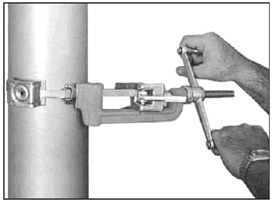
Figure 15-39 shows a strapping tool used to affix metal straps and a well tag to a well. See description in the above text. Figure 15-46 shows the well tag affixed to the well using the metal strapping.
Attaching Well Tags in Various Scenarios
Scenario #1: The Well is Used for Testing, Monitoring or Sampling. This Scenario Would Include Most Test Holes
Figure 15-40: Well Tag Attached to Test Hole Protective Casing
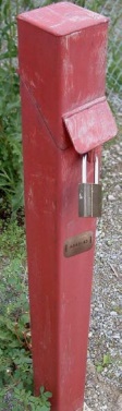
If strapping is not possible, the tag can be tack welded into place with stainless steel rods as shown in this photograph. In this case, the tag is welded on to the locked protective covering. The tag must not be affixed to the test hole casing within the locked protective covering, as the tag would not be visible.
Figure 15-41: Improperly Affixed Well Tag
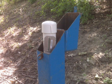
This figure shows a well tag incorrectly affixed to a test hole. In this case, if the protective well cover is closed, the well tag is not visible. Well tags are required to be permanently affixed to a casing or structure associated with the well and be visible at all times.
Figure 15-42: Well Tag Attached To Test Hole - Front View
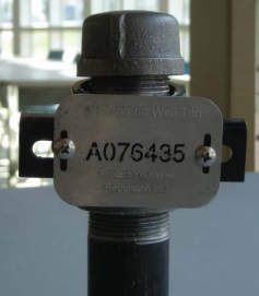
Figure 15-43: Well Tag Attached To Test Hole - Side View
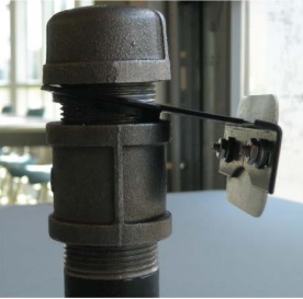
Figure 15-42 and Figure 15-43 show a well tag affixed to a metal bracket. The bracket has a slot to allow it to slide onto the well casing. A larger diameter coupling and well cap ensure the bracket stays affixed to the well and the well tag is visible.
Scenario #2: The Casing is Completely Below Finished Grade in a Flush-Mounted Well Pit (Vault)
Figure 15-44: Well Tag Affixed To Structure Associated With Flush-Mounted Well Pit (Vault)
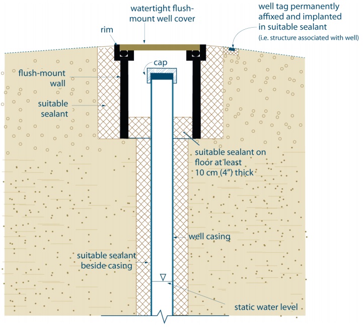
In this scenario the well tag is set into concrete slurry. The tag can be screwed or lag bolted into the concrete. The well tag must remain visible and protected from wear and tear. For further information on flush-mounted well pits (vaults) see Chapter 12: Equipment Installation and the terms “well pit” and “flush-mounted well cover” in Chapter 2: Definitions & Clarifications, Table 2-3.
Reminder: This figure is not to scale, it is for illustrative purposes for this chapter only and does not necessarily represent full compliance with the requirements found in the Wells Regulation.
Scenario #3: A Series of Dewatering Wells with Plastic Pressure Line
Figure 15-45: Well Tag Affixed to the Casing of a Point Well in a Well Cluster
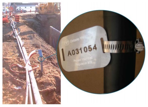
Figure 15-45 shows a well tag that was affixed to the casing using a gear clamp. Where the casing diameter is too small to affix the tag using stainless steel strapping and the method described in Figure 15-39, the tag can be attached using a gear clamp.
Scenario #4: The Casing of the Well Sticks Up and the Pump is not Positioned Over the Casing
Figure 15-46: Example of Properly Attached Well Tag
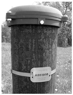
Figure 15-47: Threaded Screws Attaching Well Tag to Concrete Casing
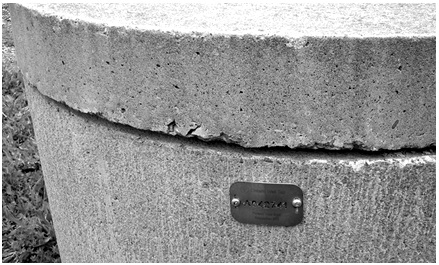
Figure 15-48: Well Tag Affixed to a Driven or Jetted Point Well
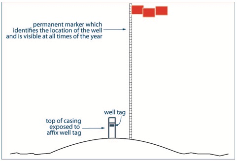
Scenario #5: The Casing Sticks Up and the Pump is Located Directly Over the Casing
Figure 15-49: Well Tag on Equipment Associated with the Well as Close as Possible to the Casing
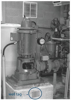
This scenario would include wells with a vertical turbine pump, or other type of pump positioned directly over the casing. Some methods include setting/screwing or lag bolting the well tag into the concrete well slab as close as possible to the casing. The well tag must remain visible and protected from wear and tear.
Scenario #6: The Pump and Casing are Located in a Pump House
Figure 15-50: Inside Pump House with Visible Well Tag on Associated Well Equipment
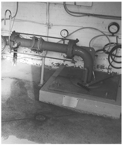
The presence of a pump house does not affect the placement of the well tag. The tag location depends on whether the pump is positioned directly over or offset from the casing. The directions in Scenario #4 or #5 should be followed, whichever is appropriate. In addition, the well owner is encouraged to post a sign on the outside of the pump house, either next to the door or on the door, indicating the well tag number.
Broken, Defaced, Illegible or Unusable Well Tags
The Wells Regulation - A person conducting an alteration, including a minor alteration, on a test hole or dewatering well with a well tag that is broken, defaced, illegible or otherwise unusable must:
- remove the well tag and return it to the Director,
- obtain a new well tag from the Ministry and, before the alteration is completed, permanently affix the well tag to the outside of the casing or to a permanent structure associated with the well, at a point where the well tag will be visible and will not be obstructed by the well cap, by other components of the well or by equipment associated with the well, and
- within 30 days after the new well tag is affixed to the casing, complete a well record with respect to the replacement of the well tag and forward a copy of the well record and the original well tag to the Director.
Best Management Practice – Referencing the Original Well Tag Number
When a well tag is replaced, the new well record for the replacement of a well tag should reference the original well tag number if it is available.
Best Management Practice – Completing Well Record When Replacing a Damaged Well Tag
When filling out a well record for the replacement of a damaged well tag in the course of a minor alteration the person altering the well should:
- provide as much information as possible on the Ministry well record form in addition to information relating to the replacement of the well tag, and
- provide the well record to the well owner and well purchaser
If legible, the old well tag number should be indicated on the well record. The person performing the alteration should provide a copy of the well record to the well purchaser and the land owner. Well owners will therefore be informed that their well tag has been changed and possess all well records for their well. In these cases, the requirements related to forwarding the well record to the Ministry apply.
Figure 15-51: Before - Well Tag Must Be Replaced
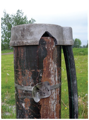
Figure 15-52: After - Well Tag Replaced
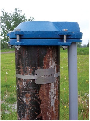
Figure 15-51 and Figure 15-52 show the before and after photographs of a broken well tag that was replaced when a minor alteration (e.g., well cap removal) was made to the well. In this case, the well cap and conduit pipe were also upgraded to remove a pathway for foreign materials to enter the well.
Safeguarding the Well Tag
The Wells Regulation - During alterations to a cased well with a well tag, the well tag must be safeguarded and, if removed, it must be re-affixed permanently to the outside of the casing or to a permanent structure associated with the well, upon completion of the alteration.
Well Tag Restricitons
To help locate and identify a test hole or dewatering well with a well tag in the field, the Wells Regulation provides the following well tag requirements that all persons must adhere to.
The Wells Regulation - It is not permitted to deface, alter, conceal or obstruct a well tag.
The Wells Regulation - It is not permitted to remove a well tag that is affixed to a well or a structure associated with the well unless:
- the person has the written consent from the Director,
- the well tag on the well that is being altered is broken, defaced, illegible or otherwise unusable, or
- the well is being altered or properly abandoned (plugged and sealed)
The Wells Regulation - It is not permitted to use a well tag issued by the Ministry except in accordance with the Wells Regulation.
Reminder: If a tagged well (e.g., deepest) in a “well cluster” is abandoned, the tag must be returned to the Director and cannot be affixed to any other well in the well cluster as this is not a permitted use of the well tag under the Wells Regulation. The best management practice titled “Using Unique Field Numbers for Untagged Existing Wells in a Well Cluster” provides recommendations that should be followed in this circumstance.
Reminder: If no alteration to a well takes place, a person must not affix a Ministry issued well tag to the well or a structure associated with the well as this is not a permitted use of the well tag under the Wells Regulation. In other words, to identify unaltered existing wells in the field a person should use unique field numbers and must not use well tags.
Notifications
The Wells Regulation does not require testing of water quality or gas during the construction of a test hole or dewatering well. Testing is typically completed after the well is ready to be put into operation by the well owner, an agent representing the well owner, or by another person. Advice and best management practices on safety considerations and identifying contaminants including gas are provided to persons constructing test holes and dewatering wells in Chapter 6: Constructing the Hole, Casing & Covering the Test Hole & Dewatering Well. If a person constructing a test hole or dewatering well identifies a gas or water quality issue; however, then there may be an obligation on the person to report the issue.
The Wells Regulation - When natural gas is encountered, the person constructing the well must immediately notify the well purchaser, the owner of the land on which the well is located and the Director.
For further information on natural gas, see Chapter 2: Definitions & Clarifications, Table 2-3.
To report an observation of natural gas, the person could use the information in the best management practice titled “Encountering Contamination, Mineralized Groundwater or Gas” in this section.
If a person constructing a water supply well (e.g., drinking water well) notices mineralized water, the person must notify the well purchaser and the owner of the land on which the well is situated that the condition exists. The information is important to allow for the determination of the type of treatment system that may be needed, the potential for mineralized water to impair other fresh groundwater zones and whether a written consent from the Director to not abandon the well is necessary.
Many test holes and dewatering wells are installed to look for and remediate groundwater quality issues. Therefore test holes and dewatering wells, as defined by the Wells Regulation, are exempt from the requirement for notification of mineralized water.
If unexpected problems with water quality or a gas, which is not considered natural gas, are observed during well construction or abandonment, the person completing the work should consider the following best management practice.
Best Management Practice – Encountering Contamination, Mineralized Groundwater or Gas
If unexpected contamination or gas is encountered in the construction (including alteration) of the test hole or dewatering well, the person constructing the test hole or dewatering well should stop work immediately to reduce serious dangers to the site crew, well owner and the environment.
To meet the obligation of reporting natural gas to the Director, the person constructing the test hole or dewatering well should contact the Ministry of the Environment through the Ministry’s Spills Action Centre (SAC) at
Unexpected contamination or gas
The Ministry can offer assistance and notify other agencies to help reduce serious dangers to the site crew, well owner and the environment.
If mineralized groundwater or other water quality problems associated with the groundwater (e.g., turbidity) are observed, the person constructing the well should immediately inform the well purchaser and the owner of the land on which the test hole or dewatering well is situated. This information can be used to determine if the water quality issues could: cause any impairment to other waters, affect sample results, treatment systems, or impact the well and other equipment associated with the well (e.g., corrosive groundwater on casing).
Reminder: For further information on mineralized water, see Chapter 2: Definitions & Clarifications, Table 2-1.
Best Management Practice – Educating the Well Owner
The well owner has responsibilities under the Wells Regulation for every well on their property. The person constructing the well should explain the following to the well owner using plain language:
- how to care for a well,
- the requirements for maintaining and abandoning the well,
- the importance of keeping the well accessible for future maintenance,
- the construction details, and
- Any other information, including the Wells Regulation and relevant internet websites.
Tools
Figure 15-53: Example of the Front Page of a Log
Figure 15-53 shows a sample of the front page of a log
The upper left box states:
- Log
- Name of Well Technician –
- Date work complete (YY/MM/DD) –
The upper right box states:
- Measurements recorded in: metric or imperial
The Well Owner and Location Information box states:
- First Name –
- Last Name –
- Address of Well Location (Street Name and Number) –
- Township –
- Lot –
- Concession –
- Country/District/Municipality –
- City/Town/Village –
- UTM Coordinates: Zone, Easting, Northing
Geo – Log Box (located immediately below Well Owner and Location Information Box): (Colours: White, Greg, Blue, Green, Yellow, Brown, Red, Black)
(Materials: Fill, Muck, Peat, Clay, Silt, Gravel, Stones, Boulders, Top Soil, Limestone, Fine Sand, Medium Sand, Coarse Sand, Dolomite, Shale, Sandstone, Slate, Quartzite, Granite, Greenstone)
(General Description: Loose, Porous, Dense, Packed, Cemented, Layered, Soft, Hard, Previously Dug or Bored, Previously Drilled, Wood Fragments)
- Headings – General Colour, Most Common Material, Other Materials, General Description, Comments, Depth (metres/feet): From – To
- There are 14 rows
Reminder: Figure 15-53 and Figure 15-54 can be photocopied front to back and used in the field.
Figure 15-54: Example of the Back Page of a Log
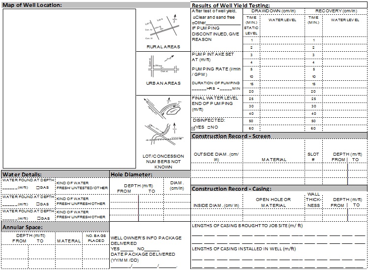
Figure 15-54 shows a sample of the back page of a log
Map of Well Location Box (located on the left side below Geo – log box): (There are three examples of how to draw a map in rural areas, urban areas and lot/concession numbers not known)
Results of Well Yield Testing Box (located on the right side below Geo – log box):
- After test of well yield – clear and free of sand or other
- If pumping discontinued, give reason –
- Pump intake set at –
- Pumping rate -
- Duration of Pumping –
- Final water level end of pumping –
- Disinfected – yes or no
- Drawdown:
- static water level:
- 1 minute of pumping:
- 2 minute of pumping:
- 3 minute of pumping:
- 4 minute of pumping:
- 5 minute of pumping:
- 10 minute of pumping:
- 15 minute of pumping:
- 20 minute of pumping:
- 30 minute of pumping:
- 40 minute of pumping:
- 50 minute of pumping:
- 60 minute of pumping:
- Recovery:
- 1 minute of recovery:
- 2 minute of recovery:
- 3 minute of recovery:
- 4 minute of recovery:
- 5 minute of recovery:
- 10 minute of recovery:
- 15 minute of recovery:
- 20 minute of recovery:
- 30 minute of recovery:
- 40 minute of recovery:
- 50 minute of recovery:
- 60 minute of recovery:
Construction Record – Screen Box (located below Results of Well Yield Testing Box):
- Outside diameter –
- Material –
- Slot # -
- Diameter (From – to) –
Construction Record – Casing Box (located below Construction Record – Screen Box):
- Inside diameter –
- Open hole or material –
- Wall thickness –
- Depth – from to
- Lengths of casing brought to job site in metres –
- Lengths of casing installed in well in metres –
Water Details Box (located below Map of Well Location Box):
- Water found at Depth –
- Kind of water – fresh, untested, other
Hole Diameter Box (located below Map of Well Location Box and to the right of the Water Details Box):
- Depth – from/to/diameter
Annular Space Box (located below the Water Details Box):
- Depth –
- Material –
- Number of bags placed -
Well Owner’s Information Package (located below the Hole Diameter Box):
- Yes or No
- Date Package Delivered –
Reminder: Figures 15-53 and Figure 15-54 can be photocopied front to back and used in the field.
Footnotes
- footnote[1] Back to paragraph ASTM International, West Conshohocken, PA, 2004. ASTM International Website.
- footnote[2] Back to paragraph ASTM D5092 – 04 – “Standard Practice for Design and Installation of Ground Water Monitoring Wells” (DOI: 10.1520/D5092-04E01). ). ASTM International, West Conshohocken, PA, 2004. ASTM International Website
- footnote[3] Back to paragraph ASTM D6089 – 97 (Reapproved 2003) – “Standard Guide for Documenting a Ground-Water Sampling Event, s. 5. Documentation Methods.” (DOI: 10.1520/D6089-97R10). ASTM International, West Conshohocken, PA, 2004.ASTM International Website.
- footnote[4] Back to paragraph This applies to gases that are not considered naturally occurring gases