6. Constructing the Hole, Casing & Covering the Test Hole or Dewatering Well
Chapter Description
This chapter covers common test hole or dewatering well construction methods and materials used in Ontario. The minimum requirements for the hole, casing and well screen and advantages and disadvantages of test holes or dewatering wells constructed using different equipment and materials are also covered. This chapter is structured to parallel the steps involved in the construction of the hole, installation of the casing, creation of the annular space and, where used, installation of the well screen and filter pack material. The filling of sealant in the annular space is covered in Chapter 7: Annular Space & Sealing. Multi-level monitoring test hole installations are covered in Chapter 8: Multi-Level Monitoring Test Holes. The requirements listed in this chapter do not apply to shallow works or other exempted wells discussed in Chapter 3: Exemptions: Wells, Activities & Experienced Professionals.
Regulatory Requirements - Hole & Casing
Relevant Sections - The Wells Regulation
Log & Field Notes – Section 12.1
Covering of Well – Section 12.2
Surface Drainage – Section 12.3
Well Pits – Subsections 12(7.1), 12(9) paragraphs 1 to 3
Casing – Section 13
Deepening of Wells – Section 13.1
Annular Space – Subsection 14.2(1), Subsection 14.2(2) paragraph 2, Subsection 14.3(1), Subsection 14.4(1), Subsection 14.4(2) paragraph 3, Subsection 14.4(3)
Double Walled Casing – Section 14.6
Information – Subsection 16(3)
Abandonment – Subsection 21(7)
The Requirements - Plainly Stated
Reminder - Figures 6-24 to Figures 6-33 at the end of this chapter show many of the requirements listed in the Plainly Stated section.
The Wells Regulation requires a person constructing a test hole or dewatering well to meet the following, unless an exemption is provided in this section or in Chapter 3: Exemptions: Wells, Activities & Experienced Professionals
Log Book and Field Notes
The person constructing a well must have an onsite, current and detailed:
- log of overburden and bedrock materials encountered when advancing the hole, and
- field notes regarding the construction of the well.
Exemptions - Log Book
The person constructing the well is required to keep up-to-date field notes but is not required to have a log of overburden and bedrock materials if the person is constructing the well by the use of a driven point (e.g., some direct push technology, or jetting).
Reminder - For further information on log books and field notes see Chapter 15: Well Records, Documentation, Reporting & Tagging.
Covering the Well
Whenever a test hole or dewatering well is left unattended during construction, the person constructing the test hole or dewatering well must cover the upper open end of the well securely in order to prevent the entry of surface water and other foreign materials.
Minimum Depth of a New Well
If a new well, other than a test hole or dewatering well, is being constructed, it must be at least 6 m (19.7′) deep unless the only useful aquifer is shallower.
In cases where the only useful aquifer if less than 6 m (19.7′) deep, the well, other than a test hole or dewatering well, must be at least 3 m (10′) deep.
Reminder - For clarification of the term “useful aquifer” see Chapter 2: Definitions & Clarifications, Table 2-3).
Exemptions - Minimum Depth of a New Test Hole or Dewatering Well
The minimum well depth requirements stated above do not apply to a new test hole or dewatering well. Other depth requirements may apply to the construction of a test hole or dewatering well (see the following two sections).
Minimum Depth of a New Test Hole or Dewatering Well with a Well Screen
In cases where a new well with a well screen is constructed by a method other than digging or by the use of a driven or jetted point, the annular space shall be filled with clean, washed gravel or sand:
- from the bottom of the well screen to at least the top of the well screen, and
- not closer than six metres to the ground surface, unless the only useful aquifer available necessitates a shallower well, in which case the top of the gravel or sand shall not be closer than 2.5 metres to the ground surface.
Reminder - Where a well screen is placed in a shallow aquifer (i.e. < 6 m deep), the depth of the new test hole or dewatering well must be such that the top of the gravel or sand in the annular space will not be closer than 2.5 metres (8.2’) to the ground surface.
Exemption - Minimum Depth of a New Test Hole or Dewatering Well with a Well Screen
The depth requirement for the top of the sand and gravel layer does not apply if the new test hole or dewatering well is scheduled to be abandoned not later than 180 days after completion of its structural stage.
This requirement does not apply if the well is constructed with a casing surrounded by a larger permanent outer casing (sometimes referred to as a double walled casing).
The depth requirement for the top of the sand and gravel layer does not apply to wells constructed by digging or by the use of a driven or jetted point.
Reminder - See Chapter 7: Annular Space & Sealing and Chapter 8: Multi-Level Monitoring Test Holes for further information on requirements for a casing surrounded by a permanent outer casing.
Records of Site Condition Regulation - *See the notes below this “Plainly Stated” section for requirements related to monitoring wells constructed as part of an ESA under O. Reg 153/04.
Well Casing and Well Screen Materials for a New Well
The casing and well screen for a new well must:
- be made of new materials,
- be clean and free of contamination, and
- not cause contamination of the water with which they are in contact.
Reminder - The requirement for a casing and well screen to be made of new materials prohibits the re-use of a casing or well screen that was previously installed in a finished well (i.e. where its structural stage has been completed). The requirement for a casing to be made of new materials does not apply to starter (working) casing.
Exemptions (180 Day Rule) - Well Casing and Well Screen Materials for a New Test Hole or Dewatering Well
The requirement for use of new materials for casing and well screen does not apply to a test hole or dewatering well if abandonment of the test hole or dewatering well is scheduled to take place not later than 180 days after completion of the structural stage of the test hole or dewatering well.
Records of Site Condition Regulation - See the notes below this “Plainly Stated” section for requirements related to monitoring wells constructed as part of an ESA under O. Reg 153/04.
Well Casing Sections for a New Test Hole or Dewatering Well
- Any casing must be watertight.
- Only continuous sections of casing (e.g., no holes or perforations or slots in the well casing) can be used in the construction of a new well.
Well Casing Seams for a New Test Hole or Dewatering Well
Any seams in the casing must be permanent and watertight.
Well Casing Joints for a New Test Hole or Dewatering Well
Joints in the casing are not allowed, unless they:
- achieve a permanent, watertight bond, such as welded steel joints, and
- are made such that the jointed casing does not impair the quality of water with which it comes in contact.
Concrete Well Casing and Casing Joints for a New Test Hole or Dewatering Well
If the casing is concrete:
- it must be fully cured and commercially manufactured,
- the concrete sections must be properly aligned so the joints are flush and the casing is centered, and
- the sections must be joined with a mastic sealing material that remains pliable and waterproof and is approved for potable water use by NSF International.
Reminder - For clarification of the terms “permanent,” “watertight” and “waterproof” see Chapter 2: Definitions & Clarifications, Table 2-3.
Exemption (30 Day Rule) - Well Casing for a New Test Hole or Dewatering Well
A new test hole or dewatering well is not required to be cased if both of the following conditions exist,
- abandonment of the test hole or dewatering well is scheduled to take place not later than 30 days after completion of the structural stage of the test hole or dewatering well, and
- the person constructing the test hole or dewatering well covers the upper open end of the well securely in a manner sufficient to prevent the entry of surface water and other foreign materials whenever the test hole or dewatering well is left unattended.
Casing Material Specifications
The minimum casing specifications (e.g. wall thickness, ASTM standard, potable water use) for new wells in the Wells Regulation do not apply to test holes or dewatering wells. Information on casing material including strength, advantages and disadvantages can be found in the “Casing Material” section on page 66 of this chapter.
Minimum Length of Well Casing Underground for a New Water Supply Well
Where the useful aquifer is greater than 6 m (19.7′) below the original ground surface, the casing for a new well, other than a test hole or dewatering well, must extend at least 6 m (19.7′) below the original ground surface.
If the only useful aquifer is located between 3 m to 6 m (10′ - 19.7′) below the ground surface, the casing for a new well, other than a test hole or dewatering well must extend at least 2.5 m (8.2′) below the level of the original ground surface.
Reminder - For clarification of the terms “useful aquifer”, “permanent”, “watertight” and “waterproof” see Chapter 2: Definitions & Clarifications, Table 2-3.
Exemption - Minimum Length of Well Casing Underground for a New Test Hole or Dewatering Well
The minimum well casing length below the ground surface specified for a water supply well does not apply to a new test hole or dewatering well without a well screen or a new test hole or dewatering well with a well screen that has been constructed by digging, jetting or by the use of a driven point.
If a well screen is installed in some new test holes and dewatering wells, casing may need to extend to at least 2.5 metres below the ground surface (see the “Minimum Depth of a New Test Hole or Dewatering Well with a Well Screen” section and its exemptions in this section of this chapter).
Surface Drainage (Earth Mounding) around the Well
The person constructing the test hole or dewatering well must ensure that the slope of the ground surface (surface drainage) is such that water will not collect or pond near the well. Proper surface drainage can be ensured by properly mounding with earth around the well and outward from the well to direct surface drainage away from the well.
Extent of Casing for a New Test Hole or Dewatering Well in an Overburden Aquifer
Unless exempt, a new test hole or dewatering well that obtains water from an overburden formation must be cased:
- from the water intake zone,
- to at least 40 cm (16″) above the highest point on the ground surface within 3 m (10′) radially from the outside of the casing after the land is properly mounded for surface drainage as measured on completion of the well’s structural stage.
There are a number of exemptions to these casing requirements which will be discussed in this “Plainly Stated” section [e.g. an uncased well, a well constructed by use of a driven point and a well completed with a flush-mounted well pit (vault)].
Reminder - For clarification of the term “well’s structural stage” see Chapter 2: Definitions & Clarifications, Table 2-3.
Extent of Casing for a New Test Hole or Dewatering Well in a Bedrock Aquifer
Unless exempt, a new test hole or dewatering well that obtains water from a bedrock formation must be cased:
- from the bedrock,
- to at least 40 cm (16″) above the highest point on the ground surface within 3 m (10′) radially from the outside of the casing after the land is properly mounded for surface drainage as measured on completion of the well’s structural stage.
There are a number of exemptions to these casing requirements which will be discussed in this “Plainly Stated” section [e.g. an uncased well, a well constructed by use of a driven point and a well completed with a flush-mounted well pit (vault)].
Sealing Casing in Bedrock for New Water Supply Wells
If the aquifer is located in a bedrock zone that is not weathered, the casing of a new drilled well, other than a test hole or dewatering well, must be sealed into the bedrock with suitable sealant to prevent impairment of the quality of the groundwater and the water in the well.
Exemption - Sealing Casing in Bedrock for New Test Holes or Dewatering Well
The requirement to seal a new casing for a water supply well into bedrock does not apply to test holes or dewatering wells.
Exemption - Casing Height 40 cm Above Ground for New Driven Point or Jetted Point Test Holes and Dewatering Wells
An exemption to the minimum casing height requirement of 40 cm (16″) above the ground surface exists if the new well is made by the use of a jetted point or driven point, and it has a visible, permanent marker.
In these cases, the casing must:
- extend a sufficient height to permit the attachment of a well tag, and
- be at least as high as the highest point on the ground surface within a 3 m (10′) radius of the well’s casing for any new well after ground surface is properly mounded with earth to direct surface drainage away from the well as measured on completion of the well’s structural stage.
The permanent marker must also identify the location of the well and be visible at all times of the year.
Reminder - For additional information on casing height and surface drainage see Chapter 9: Completing the Test Hole or Dewatering Well Structure.
Reminder - For clarification of the terms “water intake zone,” “water producing zone” and “weathered bedrock” see Chapter 2: Definitions & Clarifications, Table 2-3.
Exemptions - Well Casing Height for a New Test Hole or Dewatering Well Completed with a Flush-Mounted Well Cover
A new cased test hole or cased dewatering well is not required to be cased above the ground surface if the well:
- is located where vehicle or pedestrian traffic is likely to pass directly over the well,
- is completed with a flush-mounted watertight commercially manufactured well cover sufficient to prevent entry of surface water and other foreign materials into the well, and
- has a cover that is sufficiently strong, durable and well-installed to protect the well from damage, or the well cover is covered with a metal plate that is sufficiently large and sufficiently strong, durable and well-installed to protect the well cover and the well from damage.
Reminder - For additional information on flush-mounted well covers, casing height and surface drainage see Chapter 9: Completing the Test Hole or Dewatering Well Structure.
Reminder - For additional information on flush-mounted well pits (vaults) see Chapter 12: Equipment Installation.
Casing Height and Mounding for a New Test Hole or Dewatering Well in a Well Pit that Does Not Use a Flush-Mounted Well Cover
If a new drilled well is constructed with a well pit that does not conform to the above requirements for a flush-mounted well cover, the top of the casing of the drilled well must be at least 40 cm (16″) above the floor of the well pit.
The well pit must be cased from the bottom of the well pit to at least 40 cm (16″) above the highest point on the ground surface within 3 m (10′) radially from the outside of the casing as measured upon completion of the well’s structural stage.
The ground surface around the new well pit must be properly mounded to prevent ponding near the well.
New Well Pit Construction for Wells
All new well pits are banned in Ontario, with the exception of:
- wells constructed by diamond drilling equipment that are used in connection with mineral exploration and
- test holes or dewatering wells completed with a properly constructed flush-mounted well pit (vault).
Reminder - See Chapter 12: Equipment Installation for well pit construction requirements.
Equipment and Attachments
A lightning rod is not allowed to be attached, directly or indirectly, to the casing of a well.
Deepening of an Existing Test Hole or Dewatering Well
If the well is deepened, all of the casing requirements and exemptions for new test holes and dewatering wells apply, but the existing casing can continue to be used if it appears sound.
A well is not allowed to be constructed by penetrating through the bottom of a bored or dug well by:
- means of drilling,
- the use of a jetted point, or
- the use of a driven point.
Information – Encountering Natural Gas
Where a test hole or dewatering well is constructed and natural gas is encountered, the person constructing the well must immediately notify the well purchaser, the owner of the land on which the well is situated and the Director that the condition exists.
Reminder - Detailed information, other construction requirements and annular space sealing requirements for new multi-level monitoring test hole installations are covered in Chapter 8: Multi-Level Monitoring Test Holes.
Reminder - The regulatory exemptions regarding test holes and dewatering wells allow for well technicians, engineers and geoscientists to use their professional expertise to design and install test holes and dewatering wells on a case by case basis as each situation is different.
Relevant Records of Site Condition Regulation Requirements
Records of Site Condition Regulation - Starting on July 1, 2011, O. Reg. 153/04 prescribes that the provisions of the Ontario Water Resources Act and of Regulation 903 of the Revised Regulations of Ontario, 1990 (Wells) made under that Act, that would apply to a test hole but for section 1.1, and subsections 13 (2), 14.1 (2), 14.2 (3), 14.3 (2), 14.4 (4) and 14.5 (3) of that regulation, apply to a monitoring well installed for the purpose of,
- a phase one environmental site assessment; and
- a phase two environmental site assessment.
Implications for the Qualified Person
The qualified person shall ensure that phase one and phase two environmental site assessments (ESAs) are conducted in accordance with the requirement stated above.
Implications for Casing, Well Screen and Annular Space for a New Test Hole
With respect to casing, well screen and annular space size and filling, the above requirement in O. Reg. 153/04 means that, if a new test hole is constructed and is scheduled to be abandoned not later than 180 days after the completion of its structural stage, and is to be used as a monitoring well in an ESA being conducted in support of a record of site condition, then:
- casing and well screen must be new material and the exemption for a test hole stated in this chapter does not apply,
- the annular space size and filling exemptions for a test hole stated in this chapter do not apply, and
- the annular space size and filling requirements for a test hole stated in Chapter 7: Annular Space & Sealing, Table 7-1A and Table 7-1B do apply.
Reminder - The above annular space requirements have been added to this chapter because of the minimum size of hole that is required to be created for an annular space and the installation of filter pack material in the annular space. The above requirement in O. Reg. 153/04 also affects obligations such as shallow works and annular space filling for monitoring wells. See Chapter 3: Exemptions: Wells, Activities & Experienced Professionals and Chapter 7: Annular Space & Sealing for further information.
Records of Site Condition Regulation - Please refer to O. Reg. 153/04 for RSC requirements.
Reminder - For clarification on the term “monitoring well” in the Records of Site Condition regulation see Chapter 2: Definitions & Clarifications, Table 2-2.
Implications for Well Screen Design and Placement
Records of Site Condition Regulation - Starting on July 1, 2011, amendments to O. Reg. 153/04 came into force and apply to phase two environmental site assessments (ESAs) conducted in support of records of site conditions (RSCs). For any such RSC submitted on or after this date, where a groundwater sampling method is to be used to characterize contamination or determine if the concentration of a contaminant is above, at, or below and applicable site condition standard or standard specified in a risk assessment for the contaminant, the following requirements apply to the construction of a well:
- where a monitoring well is being used, well screens shall not exceed 3.1 m (10′) in length, based on the saturated length of the screen, and
- where petroleum hydrocarbons or light non-aqueous phase liquids may be present on, in or under a phase two property, sampling depth intervals, including screened intervals of monitoring wells, shall be positioned to intersect the water table.
Implications for the Qualified Person
The qualified person shall ensure that the phase two ESA is conducted in accordance with requirements stated above, in addition to the requirements set out in O. Reg. 153/04.
Implications for Monitoring Well Construction SOPs and QA/QC
Starting on July 1, 2011, amendments to O. Reg. 153/04 came into force and apply to phase two environmental site assessments (ESAs) conducted in support of records of site conditions (RSCs). For any such RSC submitted on or after this date, the qualified person is responsible for, among other things, developing a sampling and analysis plan that will adequately assess all areas of the phase two property including the development of standard operating procedures (SOPs) for borehole drilling, soil sampling and monitoring well installation. The qualified person shall ensure there is a sampling and analysis plan that includes a quality assurance and quality control program (QA/QC). See O. Reg. 153/04 for the QA/QC requirements.
Relevant Sections - Additional Regulations or Lesgislation
Ontario Regulation 213/91 (Construction Projects) as amended made under the Occupational Health and Safety Act
Ontario Regulation 387/04 (Water Taking) as amended made under Ontario Water Resources Act
Ontario Regulation 153/04 (Records of Site Condition) as amended made under Environmental Protection Act
Relevant Standards
ASTM D 5783-95 (2006) – “Standard Guide for Use of Direct Rotary Drilling with Water-Based Drilling Fluid for Geoenvironmental Exploration and the Installation of Subsurface Water-Quality Monitoring Devices,” (DOI: 10.1520/D5783-95R06)
ASTM D 5782-95 (2006) – “Standard Guide for Use of Direct Air-Rotary Drilling for Geoenvironmental Exploration and the Installation of Subsurface Water-Quality Monitoring Devices,” (DOI: 10.1520/D5782-95R06)
ASTM D 5088-02 (2008) – “Standard Practice for Decontamination of Field Equipment Used at Waste Sites,” (DOI: 10.1520/D5088-02R08)
ASTM D 5092-04e1 – “Standard Practice for Design and Installation of Ground Water Monitoring Wells,” (DOI: 10.1520/D5092-04E01)
ASTM D 5781-95 (2006) – “Standard Guide for Use of Dual-Wall Reverse-Circulation Drilling for Geoenvironmental Exploration and Installation of Subsurface Water-Quality Monitoring Devices,” (DOI: 10.1520/D5781-95R06)
ASTM D 5784-95 (2006) – “Standard Guide for Use of Hollow-Stem Augers for Geoenvironmental Exploration and Installation of Subsurface Water-Quality Monitoring Devices,” (DOI: 10.1520/D5784-95R06)
ASTM D 5787-95 (2009) – “Standard Practice for Monitoring Well Protection,” (DOI: 10.1520/D5787-95R09)
ASTM D 5876-95 (2005) – “Standard Guide for Use of Direct Rotary Wireline Casing Advancement Drilling Methods for Geoenvironmental Exploration and Installation of Subsurface Water-Quality Monitoring Devices,” (DOI: 10.1520/D5876-95R05)
ASTM D 6282-98 (2005) – “Standard Guide for Direct Push Soil Sampling for Environmental Site Characterizations,” (DOI: 10.1520/D6282-98R05)
ASTM D 6914-04e1 – “Standard Practice for Sonic Drilling for Site Characterization and the Installation of Subsurface Monitoring Devices,” (DOI: 10.1520/D6914-04E01)
ASTM D6151-08 – “Standard Practice for Using Hollow-Stem Augers for Geotechnical Exploration and Soil Sampling” (DOI: 10.1520/D6151-97R03)
ASTM D5088 – 02(2008) – “Standard Guide for Decontamination of Field Equipment Used at Nonradioactive Waste Sites,” (DOI:10.1520/D5088-02R08)
ASTM D5608 – 01(2006) – “Standard Guide for Decontamination of Field Equipment Used at Low Level Radioactive Waste Sites,” (DOI:10.1520/D5608-01R06)
Key Concepts
Constructing the Hole
Prior to constructing a hole, the person constructing a test hole or dewatering well should research and assess the site and surrounding area using the considerations outlined in Chapter 5: Siting Considerations & Initial Planning. Proper research and assessment covers the location of aquifers, the nature of geological formations, the sources and types of contaminants, the purpose of the test hole or dewatering well and site accessibility.
Successful completion of a test hole or dewatering well depends on the use of equipment and materials that are appropriate for the environmental conditions and geological formations encountered at a site. It is important to consider the characteristics of the drill rig or other well construction equipment including the cutting action and any flushing medium (i.e., type drilling fluid and its circulation path).
Casing
Definition - The Wells Regulation defines casing as “pipe, tubing or other material installed in a well to support its sides, but does not include a well screen.”
Casing acts to stabilize the hole, prevents unconsolidated overburden materials from entering the test hole or dewatering well, accommodates the pumping equipment, and may be used to seal off or isolate unwanted formations.
Making the casing choice that is best for the specific situation involves consideration of the formation, the production capacity of the aquifer, the uses planned for the test hole or dewatering well, the size of the hole and many other factors.
Reminder - In some situations casing is not required for test holes or dewatering wells. Typically, uncased test holes or dewatering wells are used for short-term measurements or water takings and then plugged and sealed (i.e., properly abandoned). A new test hole or dewatering well is not required to be cased as long as the abandonment of the well is scheduled to take place not later than 30 days after the completion of the well’s structural stage and the person constructing the well covers the upper open end of the well securely to prevent the entry of surface water and other foreign materials when the well is left unattended. For additional information and examples of permitted uncased test holes or dewatering wells see page 62 of this chapter.
Well Screen
Definition - The Wells Regulation defines a “well screen” as perforated pipe or tubing, unsealed concrete tiles or other material installed in a well to filter out particulate matter and form the water intake zone.
To prevent water bearing formation collapse into the test hole or dewatering well and reduce sediment or particles in the well water, a well screen should be installed in all unconsolidated formations, in most semi-consolidated formations and sometimes in bedrock.
What to Consider When Constructing a Test Hole or Dewatering Well
Persons constructing test holes or dewatering wells should research, and be familiar with, the geologic formations in the areas where they construct the wells.
Geologic Formations
Geological materials encountered during test hole or dewatering well construction could include:
- overburden formations – such as clay, silt, sand, gravel, or stones
- bedrock formations – such as sandstone, limestone, granite, or other bedrock
Reminder - See Chapter 2: Definitions & Clarifications, Table 2-1, for definitions of “overburden” and “bedrock.”
Advancing holes require construction equipment and tools, cutting actions and flushing media appropriate to the geologic formations encountered in each specific hole.
Location of The Aquifer
Well purchasers, with the assistance of their licensed well technicians or environmental consultants (i.e. Professional Engineers or Professional Geoscientists), can assess and review groundwater reports and well records near the area of the proposed test hole or dewatering well to understand the subsurface conditions and their implications prior to constructing test holes or dewatering wells.
Contaminated Sites
If there is any known or suspected contamination at the site, it is important to consider the following questions:
- What decontamination procedures must be established from hole to hole?
- How are water and/or soil to be contained if contaminated?
- Where will contaminated water and/or soil be stored or disposed of?
- Who will handle the storage and disposal of contaminated water and/or soil?
- What additional health and safety precautions should be taken?
- What is the contingency plan for the rescue of any affected personnel, including identification and location of medical and emergency resources for the site?
Reminder - See Chapter 5: Siting Considerations & Initial Planning for further information on geologic formations, aquifer locations, contaminated sites and environmental site characterization.
Accessibility or Space to Work on the Site
It is important that the proper authorization to access and enter the property and to do the work be obtained from the owner of the land and any other party that has an interest in the land (e.g. tenant).
Site access or space to work on the site is an important consideration. Overhead or underground utilities or obstructions may not allow certain equipment (e.g., a drilling rig) to be admitted. Small working space or long distances from roadways may also limit equipment access to the test hole or dewatering well site. In certain situations, separation distances from sources of contaminants should also be considered (e.g. establishing background groundwater quality).
Reminder - See Chapter 5: Siting Considerations & Initial Planning for further information on accessibility or space to work at the test hole or dewatering well site.
Purpose of the Test Hole or Dewatering Well
There are many reasons to construct a test hole or dewatering well. This may dictate what type of construction method and equipment are appropriate to construct a test hole or dewatering well.
The reasons for constructing a test hole or dewatering well include:
- Dewatering for construction
- Testing and monitoring
- Locating groundwater and contaminants
- Pumping water into an aquifer (recharge well)
- Injecting products to treat contaminated groundwater
- Using pump and treat systems to capture, treat and dispose of free product (portion of the contaminant that is not dissolved in water) and contaminated groundwater
Impact of the Hole
Before constructing the test hole or dewatering well, it is important to consider what impact the well construction may have on the environment around it.
Reminder - It is very difficult to correct mistakes after the fact. It is important, therefore, to utilize and execute best management practices throughout the test hole or dewatering well construction process.
Constructing Test Holes or Dewatering Wells by Different Methods
The following sections provide the key considerations when constructing the hole. Figure 6-24 to Figure 6-33, on pages 119 to 128 of this chapter, further illustrate well construction considerations.
Choosing a Construction Method
The construction method:
- should be able to penetrate the geological formation,
- should allow the person constructing the test hole or dewatering well to get representative samples of geological formation material, to identify the boundaries of permeable zones and contaminated zones,
- must allow for the proper recording of formations, including aquifers, encountered during construction,
- must not contaminate the groundwater or the environment, and
- unless otherwise exempt, must meet the minimum depth and diameter requirements of the Wells Regulation (Figure 6-24 to Figure 6-33, on pages 119 to 128 of this chapter).
In many cases, the same equipment is used to construct more than one test hole or dewatering well for a project. Where there is no risk of contamination, the equipment does not have to be cleaned after each test hole or dewatering well is constructed before it can be re-used. Nonetheless, the construction method chosen must not contaminate the groundwater and the environment.
Table 6-1 provides methods, characteristics and some general advantages and disadvantages of various well construction systems in particular formations
| Well Construction System | Characteristics | Advantages | Disadvantages |
|---|---|---|---|
| Hollow- and Solid-Stem Auger |
|
|
|
| Direct Push |
|
|
|
| Driving |
|
|
|
| Jetting |
|
|
|
| Conventional Rotary Drilling Water or Mud |
|
|
|
| Conventional Rotary Drilling Air |
|
|
|
| Reverse Circulation Rotary |
|
|
|
| Dual Wall Reverse Circulation Rotary |
|
|
|
| Dual Rotary/ Casing Advancement |
|
|
|
| Down-the-Hole Hammer (Air Percussion Rotary) |
|
|
|
| Cored Hole / Diamond Drilling |
|
|
|
| Cable Tool |
|
|
|
| Bucket Auger |
|
|
|
| Excavator |
|
|
|
| Sonic |
|
|
|
| Horizontal (Directional) Drilling |
|
|
|
Table 6-2 provides some general information on the speed of the construction equipment, which is used in a particular environment and formation, to construct different types of wells. The table does not provide a ranking system necessarily but instead deals with ease of use in specific overburden and bedrock.
Rate of Penetration: 1=Impossible 2=Difficult 3=Slow 4=Medium 5= Rapid 6=Very Rapid
| Type of Formation | Cable Tool | Direct Rotary (with fluids) | Direct Rotary (with air) | Down-the-hole air | Drill-through casing hammer4 | Reverse Rotary (with fluids)4 | Reverse Rotary (Dual Wall) | Hydraulic Percussion | Jetting | Driven ** | Auger | Sonic | Direct Push*** | Digging |
|---|---|---|---|---|---|---|---|---|---|---|---|---|---|---|
| Dune sand | 2 | 5 | Not Recommended | Not Recommended | 6 | 5* | 6 | 5 | 5 | 3 | 3-4 | 5-6 | 5-6 | 5 |
| Loose sand and gravel | 2 | 5 | Not Recommended | Not Recommended | 6 | 5* | 6 | 5 | 5 | 3 | 3-4 | 5-6 | 5-6 | 5 |
| Quicksand and flowing sand | 2 | 5 | Not Recommended | Not Recommended | 6 | 5* | 6 | 5 | 5 | Not Applicable | 1 | 4-5 | 1 | * |
| Loose boulders in alluvial fans or glacial drift | 3-2 | 2-1 | Not Recommended | Not Recommended | 5 | 2-1 | 4 | 1 | 1 | Not Applicable | 3 | 3-4 | 2-3 | 2 |
| Clay and silt | 3 | 5 | Not Recommended | Not Recommended | 5 | 5 | 5 | 3 | 3 | Not Applicable | 3 | 5-6 | 5 | 3 |
| Firm shale | 5 | 5 | Not Recommended | Not Recommended | 5 | 5 | 5 | 3 | Not Applicable | Not Applicable | Not Applicable | 2 | Not Applicable | Not Applicable |
| Sticky shale | 3 | 5 | Not Recommended | Not Recommended | 5 | 3 | 5 | 3 | Not Applicable | Not Applicable | Not Applicable | 2-3 | Not Applicable | Not Applicable |
| Brittle shale | 5 | 5 | Not Recommended | Not Recommended | 5 | 5 | 5 | 3 | Not Applicable | Not Applicable | Not Applicable | 2-3 | Not Applicable | Not Applicable |
| Sandstone – poorly cemented | 3 | 4 | Not Recommended | Not Recommended | Not Applicable | 4 | 5 | 4 | Not Applicable | Not Applicable | Not Applicable | Not Recommended | Not Applicable | Not Applicable |
| Sandstone – well cemented | 3 | 3 | 5 | Not Recommended | Not Applicable | 3 | 5 | 3 | Not Applicable | Not Applicable | Not Applicable | Not Recommended | Not Applicable | Not Applicable |
| Chert nodules | 5 | 3 | 3 | Not Recommended | Not Applicable | 3 | 3 | 5 | Not Applicable | Not Applicable | Not Applicable | Not Recommended | Not Applicable | Not Applicable |
| Limestone | 5 | 5 | 5 | 6 | Not Applicable | 5 | 5 | 5 | Not Applicable | Not Applicable | Not Applicable | Not Recommended | Not Applicable | Not Applicable |
| Limestone with chert nodules | 5 | 3 | 5 | 6 | Not Applicable | 3 | 3 | 5 | Not Applicable | Not Applicable | Not Recommended | Not Applicable | Not Applicable | |
| Limestone with small cracks or fractures | 5 | 3 | 5 | 6 | Not Applicable | 2 | 5 | 5 | Not Applicable | Not Applicable | Not Recommended | Not Applicable | Not Applicable | |
| Limestone – cavernous | 5 | 3-1 | 2 | 5 | Not Applicable | 1 | 5 | 1 | Not Applicable | Not Applicable | Not Recommended | Not Applicable | Not Applicable | |
| Dolomite | 5 | 5 | 5 | 6 | Not Applicable | 5 | 5 | 5 | Not Applicable | Not Applicable | Not Recommended | Not Applicable | Not Applicable | |
| Basalts – thin layers in sedimentary rocks | 5 | 3 | 5 | 6 | Not Applicable | 3 | 5 | 5 | Not Applicable | Not Applicable | Not Recommended | Not Applicable | Not Applicable | |
| Basalts – thick layers | 3 | 3 | 4 | 5 | Not Applicable | 3 | 4 | 3 | Not Applicable | Not Applicable | Not Recommended | Not Applicable | Not Applicable | |
| Basalts – highly fractured (lost circulation zones) | 3 | 1 | 3 | 3 | Not Applicable | 1 | 4 | 1 | Not Applicable | Not Recommended | Not Applicable | Not Applicable | ||
| Metamorphic rocks | 3 | 3 | 4 | 5 | Not Applicable | 3 | 4 | 3 | Not Applicable | Not Recommended | Not Applicable | Not Applicable | ||
| Granite | 3 | 3 | 5 | 5 | Not Applicable | 3 | 4 | 3 | Not Applicable | Not Recommended | Not Applicable | Not Applicable |
* Assuming sufficient hydrostatic pressure is available to contain active sand (under high confining pressures)
** Driven means manual and mechanically assisted methods (hand held electric or pneumatic rotary hammers)
*** Direct push means cone penetration testing (CPT) rigs or trucks or track driven machines with hydraulic powered percussion hammers or vibratory heads
**** Digging in quicksand and flowing sand is not recommended because the hole is not cased as it is advanced and the formation will likely slough.
Construction Method and Contamination
While various well construction methods can be used in the construction of test holes and dewatering wells, the potential presence of contaminants makes some methods more appropriate than others in certain situations.
For example, some methods require the use of large amounts of water which can:
- become contaminated, requiring special containment and disposal procedures,
- cause the contaminant to move, further spreading the impacted area, and/or
- dilute any contaminant that is present, and therefore, affect the integrity of samples.
Other methods can generate large amounts of overburden or cuttings, which also require special containment and disposal.
Construction Method for Controlling and Collecting Groundwater
In addition to the considerations in the “Choosing a Construction Method” section on page 21 of this chapter, construction of dewatering systems used to control and/or collect groundwater should consider the following:
- size and depth of excavation for construction dewatering,
- proposed methods of excavation and ground support for construction dewatering,
- types and depths of proposed foundations,
- proximity of existing structures and their foundations,
- planned schedule for dewatering (e.g., how quickly the groundwater needs to be lowered to install a structure),
- formation characteristics (e.g., flowing well conditions),
- nature of contamination at the site for a remediation system, and
- nature of contamination off-site to reduce the risk of mobilizing contaminants.
Open pumping and pre-drainage systems are two types of dewatering systems used to control and/or collect groundwater. Open pumping systems consist of pumping excavations. Pre-drainage systems consist of well points, suction wells, deep wells, ejector systems and horizontal drains. Table 6-3 provides characteristics, advantages and disadvantages of pre-drainage systems. For further explanation, advantages and disadvantages of open pumping systems see Tables 16.1 and 16.2 from Construction Dewatering and Groundwater Control – New Methods and Applications: Third Edition
| Conditions | Well Point System | Suction Wells | Deep Wells | Ejector Wells | Horizontal Drains |
|---|---|---|---|---|---|
| Silty & clayey sands | Good | Poor | Poor to Fair | Good | Gooda |
| Clean sands & gravel | Good | Good | Good | Poor | Good |
| Stratified soils | Good | Poor | Poor to fair | Goodc | Good |
| Clay or rock at sub-grade | Fair to good | Poor | Poor | Fair to good | Goodb |
| Conditions | Well Point System | Suction Wells | Deep Wells | Ejector Wells | Horizontal Drains |
|---|---|---|---|---|---|
| High hydraulic conductivity | Good | Good | Good | Poor | Good |
| Low hydraulic conductivity | Good | Poor | Poor to fair | Good | Good |
| Proximate recharge | Good | Poor | Poor | Poor to good | Good |
| Remote recharge | Good | Good | Good | Good | Good |
| Conditions | Well Point System | Suction Wells | Deep Wells | Ejector Wells | Horizontal Drains |
|---|---|---|---|---|---|
| Rapid drawdown | OK | OK | Unsatisfactory | OK | OK |
| Slow drawdown | OK | OK | OK | OK | OK |
| Conditions | Well Point System | Suction Wells | Deep Wells | Ejector Wells | Horizontal Drains |
|---|---|---|---|---|---|
| Shallow (<6.1 m (20′) below water table) | OK | OK | OK | OK | OK |
| Deep (>6.1 m (20′) below water table) | Multiple stages required | Multiple stages required | OK | OK | Special equipment |
| Cramped | Interferences | Interferences | OK | OK | May be OK |
| Conditions | Well Point System | Suction Wells | Deep Wells | Ejector Wells | Horizontal Drains |
|---|---|---|---|---|---|
| Normal spacing | 1.5 – 3 m (5 – 10′) | 6 – 12 m (20 – 40′) | >15 m (>50′) | 3 – 6 m (10 – 20′) |
| Conditions | Well Point System | Suction Wells | Deep Wells | Ejector Wells | Horizontal Drains |
|---|---|---|---|---|---|
| Per Unit | 0.4 – 95 L/m (0.1 – 21 gpm) | 190 – 2,270 L/min (42—500 gpm) | 0.4 – 11,360 L/min (0.1 – 2,499gpm) | 0.4 – 150 L/min (0.1 – 33 gpm) | |
| Total System | Low -18,930 L/m (Low – 4,164 gpm) | 7,570 – 94,635 L/m (1,165 – 20,817 gpm) | Low – 227,125 L/min (Low – 49,962 gpm) | Low – 3,785 L/min (Low-833 gpm) | Low – 7,570 L/min (Low – 1,165 gpm) |
| Efficiency with accurate design | Good | Good | Fair | Poor | Good |
a If backfilled with sand or gravel.
b If keyed into clay or rock.
c If double pipe ejectors with well screen full length are used.
Reminder - Take all possible precautions to ensure that any contaminated water, soil, vapours or airborne contaminants are contained during all phases of construction.
If groundwater is anticipated to discharge or is discharging from a well during construction at a volume of more than 50,000 litres (11,000 Imp gal) on any one day, a Permit To Take Water under the Ontario Water Resources Act may be required. More information on Permit To Take Water approvals can be found in Chapter 5: Siting Considerations & Initial Planning and on Ontario.ca.
Reminder - The person constructing the well should ensure that the groundwater, drill cuttings and other materials discharging from the well do not cause environmental impacts such as erosion, impairment of surface water courses and off-site flooding. The use of settling pits on the property may be needed to contain the materials and prevent the above problems. A sewage works environmental compliance approval under the Ontario Water Resources Act may be required if the person constructing the well discharges the water, drill cuttings or other material and the discharge capacity exceeds 10,000 litres per day. A guide to explain the sewage works process can be found on Ontario.ca.
Figure 6-1: Equipment Used for Driven Point Well Construction
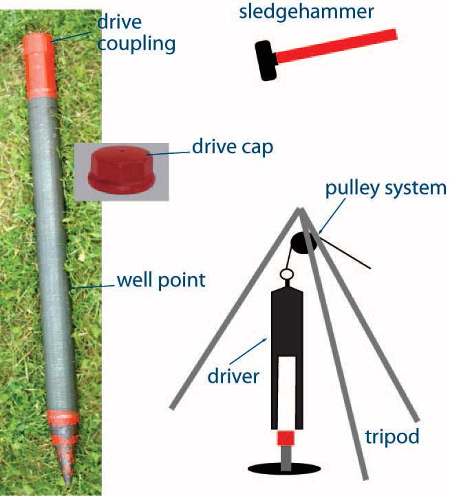
Figure 6-1 shows a typical steel well point. A well point is installed by attaching it to a length of casing using a coupling and exerting force with a sledgehammer or a driver to the drive cap. A driver is weighted and fits over the cap and is most commonly used in conjunction with a tripod and pulley system. To drive the well point deeper, additional lengths of casing attached with couplings are used.
Depending on the formation in which the well is being constructed, the person constructing the well may pre-construct the hole using one of the other methods listed above in Table 6-3.
Well points may also be jetted into place, installed using a slide hammer (Figure 6-2), or installed with the use of a hydraulically powered direct push rig, such as the one shown in Figure 6-3.
Figure 6-2: Slide Hammer - A Method of Manual Direct Push
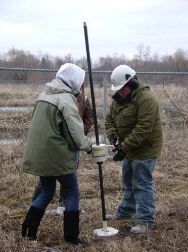
Figure 6-2 shows two people using a slide hammer to drive a rod into the ground. Depending on the conditions of the soil, this method may be used to drive wells to depths of 10 m (33′) or more. A test hole (e.g., piezometer) may be installed by this method.
Figure 6-3: Direct Push Rig
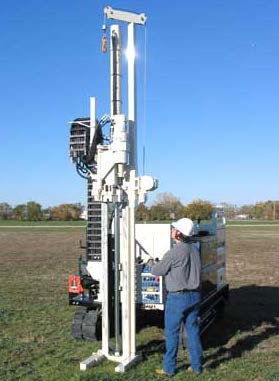
Figure 6-3 shows a direct push rig, which is hydraulically powered. It uses percussion and static force to push the sampling equipment into the ground. The greater force allows larger diameter tools to be driven into the ground.
Figure 6-4: Sonic Drill Rig
Figure 6-4 shows a sonic drill rig which uses high-frequency vibration combined with down-pressure and rotation to advance drilling tools into the ground.
Figure 6-5: Auger Rig Using Hollow-Stem Auger Flight
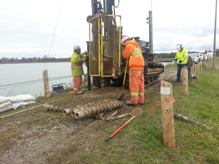
Auger rigs like the one shown in Figure 6-5 are commonly used in the geotechnical and environmental drilling industries for both soil testing and groundwater investigations. This rig is powered by a deck mounted engine, capable of extremely high rotational torque. Depth, however, will limit the machine’s rotational torque capabilities. A lot of energy is required to advance a hole due to the large surface area of augers.
Flushing Methods
Drilling fluids (flushing media) are an important consideration when choosing a construction method. During certain well construction, drilling fluids will help to do the following:
- Lubricate the drill bit, string and bearings to prevent breakdowns
- Clean and cool the bit to allow for continued long periods of drilling without having to replace the bit
- Stabilize the hole by exerting enough pressure to prevent caving
- Seal the hole wall to reduce fluid loss to the formation
- Lift well cuttings from the bottom of the hole to surface to allow drilling to continue into the formation
There are three main flushing methods:
- Fluid-based [e.g., water; water and bentonite (clay additives); water and polymeric additives; and water, bentonite (clay additives), and polymeric additives]
- Air-based (e.g., dry air; air and water mist; air with a film of water containing a foam; and air, foam and film strengthening materials, such as polymers and bentonite)
- Dry or mechanical-based (uses a mechanical action)
For additional information on flushing media (drilling fluids) see:
- Table 7: Advantages and Disadvantages of Flushing Methods for Drilling Monitoring Wells, from the Fleming College Continuing Education Course Manual: Monitoring Wells – Construction (for Ontario Well Technicians),
- Practical Handbook of Environmental Site Characterization and Ground-Water Monitoring, Second Edition
footnote 8 , - Chapters 16, 17 and 18 of Construction, Dewatering and Groundwater Control – New Methods and Applications, Third Edition
footnote 9 , and - Chapter 8: Drilling Fluids, from Groundwater and Wells, Third Edition
footnote 10 .
Reminder - The use of flushing media with polymeric additives (or polymers) may not be appropriate where a test hole is installed as part of a groundwater quality sampling program. Increased biological activity causing considerable alterations to groundwater quality lasting a long period of time has been cited as a cause for concern and resulted in the restriction of the use of flushing media with polymeric additives for the construction of test holes in certain jurisdictions of the United States (US EPA, 1991). The Professional Geoscientist or Professional Engineer responsible for the environmental project should assess the geological conditions and scope of the project to determine if the use of flushing media with polymeric additives for the construction of test holes is appropriate, on a case by case basis.
The use of any flushing media with polymeric additives should be clearly documented
Size of the Test Hole or Dewatering Well
During construction of a well, an annular space is created when the size of the hole in the ground is larger than the casing and well screen diameter.
A properly filled annular space around a casing will:
- isolate a discrete zone,
- prevent migration of surface water and other foreign materials into the well and aquifers,
- prevent migration of groundwater and/or contaminants between water bearing formations and subsurface formations,
- prevent migration of groundwater and/or contaminants between water bearing formations and the ground surface,
- prevent aquifer depressurization by stopping the upward migration of water along the casing, or
- prevent gas migration.
Where an annular space is created, the space must be large enough to ensure:
- filter pack (clean washed gravel and sand) can be placed beside a well screen, if applicable, and
- suitable sealant (grout) can fill and adhere around the entire outer well casing to prevent surface water, groundwater, natural gas and other foreign materials from migrating along the outside of the well casing.
Figures 6-24 to 6-33 at the end of this chapter show many of the requirements listed in Table 6-4.
Table 6-4 may not apply to situations where an inner casing is surrounded by a larger diameter permanent outer casing. For further information see the double walled casing requirements in the “Plainly Stated” section of Chapter 7: Annular Space & Sealing.
Additional details on annular space sealing requirements for test holes and dewatering wells that will be in use for longer than 180 days can be found in Chapter 7: Annular Space & Sealing, Table 7-1.
In the case of a test hole or dewatering well constructed by use of a driven point that creates an annular space, see Chapter 7: Annular Space & Sealing, for annular space sealing considerations.
| Bored Well with Concrete Casing ≥ 6 m Deep | Bored Well with Concrete Casing < 6 m (19.7’) Deep | Dug (or Excavated) Well, Jetted Well or Wells Constructed by the Use of a Driven Point | Drilled Well or Any Other Well ≥ 6 m Deep That is not Listed on this Table | Drilled Well or Any Other Well < 6 m (19.7’) Deep That is not Listed on this Table | |
|---|---|---|---|---|---|
| Minimum Depth of Annular Space below Ground Surface at the Diameter Specified in the Next Row | ≥6 m (19.7′)** | Where no well screen is installed:
|
No minimum | > 6 m (19.7′)** | Where no well screen is installed:
|
| Minimum Diameter of Hole Greater than Outer Casing Diameter to Create Annular Space | ≥15.2 cm (6″) from the ground surface to ≥ 2.5 m (8.2′) below the ground surface | ≥15.2 cm (6″) from the ground surface to ≥ 2.5 m (8.2′) below the ground surface | No minimum | ≥ 7.6 cm (3″) | ≥ 7.6 cm (3″) |
| Minimum Diameter of Hole Greater than Outer Casing Diameter to Create Annular Space | ≥ 7.6 cm (3″) from >2.5 m (8.2′) below the ground surface | ≥ 7.6 cm (3″) from >2.5 m (8.2′) below the ground surface | No minimum | If rotary drilling equipment is used and centralizers are attached to casing > 6 m below the ground surface: ≥ 5.1 cm (2″) | If rotary drilling equipment is used and centralizers are attached to casing > 6 m below the ground surface: ≥ 5.1 cm (2″) |
| Minimum Diameter of Hole Greater than Outer Casing Diameter to Create Annular Space | ≥ 7.6 cm (3″) from >2.5 m (8.2′) below the ground surface | ≥ 7.6 cm (3″) from >2.5 m (8.2′) below the ground surface | No minimum | If cable tool equipment is used and a breakaway guide is attached 2 m above the bottom of any casing: ≥ 5.1 cm (2″) | If cable tool equipment is used and a breakaway guide is attached 2 m above the bottom of any casing: ≥ 5.1 cm (2″) |
* For new test holes or dewatering wells not scheduled to be abandoned within 180 days after completion of the well’s structural stage (see the text before Table 6-4).
** If any annular space is created below 6 m below the ground surface, it must be sealed as described in Chapter 7: Annular Space & Sealing.
*** The requirement does not apply to situations where an inner casing is surrounded by a larger diameter permanent outer casing (see the text before Table 6-4 and exemptions in “Plainly Stated” section of this chapter).
Best Management Practice – Determining the Size of the Test Hole or Dewatering Well Where Casing is Installed
A person constructing a cased well should create a hole diameter of sufficient size that will allow for:
- Best Management Practice – Determining the Size of the Test Hole or Dewatering Well Where Casing is Installed
- suitable sealant to be placed in the annular space around the casing and adhere to the casing and formation.
In most subsurface conditions, a person constructing a cased well should create a test hole or dewatering well diameter that is at least 10 cm to 20 cm (4″ to 8″) larger than the outer diameter of the casing. The larger size of hole facilitates the proper placement of the suitable sealant and filling materials in the annular space using a tremie pipe.
Care should be taken in determining the size of the hole. The person constructing the hole should ensure that the hole is able to accommodate a casing of sufficient size to allow for the installation of necessary downhole equipment (e.g., pumps, pressure transducers, and water level meters).
Reminder - The same minimum hole diameter and annular space requirements and exemptions apply whether the casing is cylindrical or not, See Table 6-4 for additional details. For additional information on annular space and sealing requirements, see Chapter 7: Annular Space & Sealing.
Best Management Practice – Size of the Test Hole or Dewatering Well Annular Space
A person constructing a test hole or dewatering well should always apply the minimum specifications in Table 6-4, the “Determining the Size of the Test Hole or Dewatering Well” BMP above and the Optimum Artificial Filter Pack Characteristics” BMP in the Artificial Filter Packs section of this Chapter, regardless of the length of time that a well is scheduled to be in operation.
Constructing Straight and Plumb Holes
No single drilling construction method is best for every type of test hole or dewatering well or every geologic condition. Each situation may call for a change in the cutting action, flushing medium and equipment, as the construction progresses.
A crucial part of constructing a good vertical hole is ensuring that the hole is straight and plumb to minimize problems with placing the casing, placing filling material or suitable sealant in the annular space around the entire well screen and casing, installing monitoring equipment and collecting samples.
Common Causes of Crooked Vertical Holes
Some of the more common reasons that a hole is not straight include:
- Excessive pull down on drill string
- Drilling aggressively through varying hard and soft formations
- Deflecting off boulders
- Collaring hole on sloping bedrock surface
Figure 6-6: A Crooked Hole as a Result of Drilling Tools Deflecting Off Boulders
Reminder - During construction, a common practice is to use a mirror to reflect sunlight down the hole to permit a visual check on the straightness of the hole. The mirror observation method can be used to check for straightness if a plumb-bob is lowered down the hole. Specifically, a mirror can be used above the water level or when the test hole or dewatering well is dry to check the following:
- straightness of the hole,
- water levels,
- water entry points in cascading conditions or during pumping,
- condition of the hole or casing,
- occurrence of obstructions in the hole such as boulders, and
- occurrence of water leakage and unconsolidated material at bedrock – casing interface.
The person constructing the test hole or dewatering well using rotary drilling equipment should use a mirror and watch the drill string when drilling and tripping in/out to see if the drill string stays in the centre of the casing in the collar area. If the drill string does not stay in the centre of the casing, the hole is not plumb and straight. If using this method, the person constructing the well should ensure that:
- the rig is stable and level, and
- a new or well maintained drill string is used to minimize the degree of deviation within the string.
Similarly, the person constructing the test hole or dewatering well using cable tool drilling equipment should look at the relationship of the drill cable to the top of the casing. If the cable is always centred in the casing, then the hole is plumb and straight. If the cable is not centred, then the hole is not plumb and straight.
Best Management Practice – Using Stabilizers and Good Construction Techniques
To help minimize the occurrence of crooked or out of plumb holes, good construction techniques should be used in combination with stabilizers on the drilling tools and inclinometers to measure the angle of the holes.
Figure 6-7: A Drill Bit Stabilizer
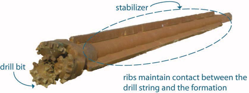
Figure 6-7 shows a drill bit stabilizer. The circled portion shows the stabilizer has three ribs attached to the rod. The use of a stabilizer such as the one shown here, will help keep the hole straight by maintaining wall contact over a long distance.
Best Management Practice – Straight Holes when Diamond Drilling
When diamond drilling is used to construct the test hole or dewatering well, the person constructing the well should implement the following procedures to ensure a straight hole:
- Properly maintain the downhole equipment (e.g., reaming shells and core barrels)
- Ensure the rig is stable and level
Drilling Straight Non-Vertical Holes (Directional Drilling)
When drilling non-vertical holes, it is important to maintain the desired angle and keep the hole straight. Maintaining the desired angle is difficult as the equipment will naturally migrate up or down, depending on the amount of thrust. Figure 6-8 (below) illustrates this deviation. Deviation can be avoided by applying consistent and adequate thrust to the drill string.
Figure 6-8: Deviation in Non-Vertical Holes
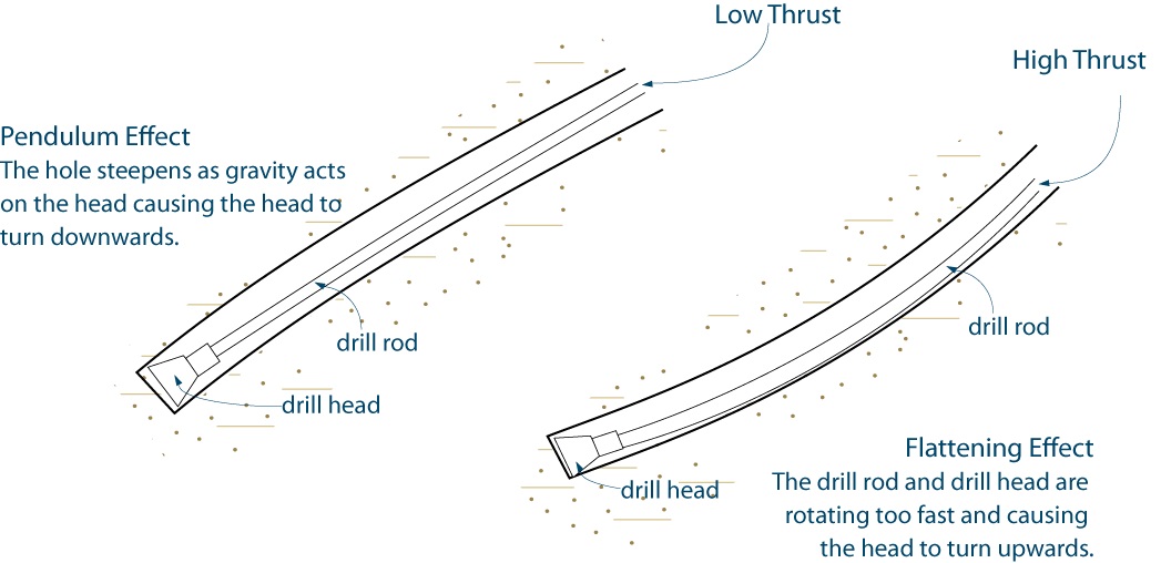
The left side of Figure 6-8 shows a cross section of the pendulum effect that can occur when drilling non-vertical holes. If the drill rod is not turning fast enough, gravity will pull the drill head down causing the hole to steepen as the drill head turns further and further downwards.
The right side of Figure 6-8 shows the opposite scenario where the drill rod is turning at a higher rate of speed which can result in the Flattening Effect. The drill rod is rotating too fast and is causing the drill head to turn upwards and the drill hole starts to flatten.
Best Management Practice – Drilling Straight Non-Vertical Holes
When using directional drilling to construct test holes and dewatering wells, using the following equipment will help keep the hole straight:
- Steerable downhole motors
- Heavy drill collars in conjunction with stabilizers
- Wedges to control the deviation and maintain the desired angle
- A larger diameter drill stem
Creation of Unintended Cavities, Voids and Spaces Outside the Hole Area
Several factors can contribute to the creation of a cavity, void or space during test hole or dewatering well construction. These include:
- Cutting action
- Drilling system
- Flushing medium
- Local geology
- Casing accessories such as drive shoes, casing welds, weld rings and couplings
- Drill cuttings being pushed out of the hole
Best Management Practice – Reducing the Risk of Creating Spaces and Voids
To reduce the risk of unintended small voids and spaces that may be difficult to fill and seal, the person constructing the drilled test hole or dewatering well should:
- Not use a drive shoe with a larger outside diameter than the casing (Table 6-10).
- Minimize the thickness of multiple pass welds (Table 6-7).
- Avoid using a weld ring as it can create a larger annular space. Instead, a thicker walled casing [e.g. 6.4 mm (0.250″) – Table 6-10] should be used to increase the surface area at the ends of the casing to be welded. As an alternative, the person constructing the test hole or dewatering well should corner cut the casing end at a 45 degree angle. The thicker casing provides a stronger welded joint, without causing a larger annular space. (Table 6-10).
- Minimize the use of band and coupled casing. Welded casing sections should be used instead.
- Use minimum volumes of air or water-based flushing media with good drilling practices to minimize hole erosion and avoid losing circulation.
For a well constructed by the use of a driven point, the person constructing the well should verify that the widest part of the driven point matches the outside diameter of the casing or screen. A wider point could create a very small annular space that is difficult to seal.
If any voids are created on the outside of a casing as a result of the well construction activity, see Chapter 7: Annular Space & Sealing for an explanation of how to seal the voids.
Covering the Hole
An open hole or excavation is not only a safety hazard for children, farm animals and other living things, it is also an open and direct pathway into the aquifer or other subsurface formation. An open test hole or dewatering well can allow contaminants from spills near the test hole or dewatering well to enter the open hole and impair the aquifer.
The Wells Regulation - The Wells Regulation requires that whenever a test hole or dewatering well, other than a shallow works, under construction is left unattended, including during a minor alteration or the installation of a pump, the person constructing the well must cover the upper open end of the test hole or dewatering well securely in a manner sufficient to prevent the entry of surface water and other foreign materials into the well.
The Wells Regulation - The person constructing the well must also ensure that the surface drainage is such that water will not collect or pond in the vicinity of the well.
Temporary covers need to prevent surface water or other foreign materials from entering the hole, and be secure enough to prevent physical hazards and vandalism. Covering a test hole or dewatering well may include installing a lockable watertight well cap on top of the test hole or dewatering well and sealing the cover to the well casing.
Best Management Practice – Covering Test Holes or Dewatering Wells Without Casing
In situations where casing is not required, a temporary vertical tube and horizontal cover that is larger than the hole should be installed into the ground and around the test hole or dewatering well to prevent hole collapse and the entry of surface water and other foreign materials. For further information see Figure 6-27 to Figure 6-29.
Reminder - For further information on wells without casing and other best management practices see the “Exemption from the Requirement to Case the Test Hole or Dewatering Well” section in this chapter.
Reminder - For information on best management practices to cover a shallow works please see Chapter 3: Exemptions: Wells, Activities & Experienced Professionals.
A person constructing a test hole or dewatering well also must ensure a cover meets the Ontario regulation for Construction Projects (Ontario Regulation 213/91) of the Occupational Health and Safety Act requirements to prevent physical accidents at the well site for the public and workers. The person constructing the test hole or dewatering well should also take other reasonable steps to secure the site. As such, leaving the drill rods and other tools in the hole and placing a piece of plywood on top of the well is not a proper well cover.
Recording Geological Information
The Wells Regulation - The Wells Regulation requires that the person constructing a new test hole or dewatering well make a log of the overburden and bedrock materials (geological formations) and keep up to date field notes at the well site. This requirement also applies if the person is deepening the well.
A test hole or dewatering well that is constructed by use of a driven point is exempt from the requirement to make and keep a log of overburden and bedrock materials but field notes are required to be made, kept up to date, and be available at the well site.
Reminder - See Chapter 15: Well Record, Documentation, Reporting & Tagging for further information on log book and field notes, and an example of a log book entry sheet.
| Major Divisions | Subdivisions | Field Identification | Other Properties |
|---|---|---|---|
| Coarse-Grained Soils / Sediments | Gravel |
|
|
| Coarse-Grained Soils / Sediments | Sand |
|
|
| Fine-Grained Soils / Sediments | Silt |
|
|
| Fine-Grained Soils / Sediments | Clay |
|
|
| Soil/Sediment Mixture | Glacial Till |
|
|
| Other | Fill |
|
|
| Other | Cobbles |
|
|
| Other | Boulders |
|
|
Reminder - Table 6-5 provides information on one of several grain-size scales used. A grainsize scale widely used and accepted by geologists, the Udden-Wentworth grain-size scale, is described in Sedimentary Rocks in the Field
The person constructing the test hole or dewatering well should collect representative samples at measured depths and at intervals that will show the complete geological character of the hole. For example, formation samples could be collected at 1.5 m (5′) intervals and at every change in formation materials. The field notes should document the:
- changes in formation materials including the top and bottom of each material/unit encountered,
- observed characteristics of each formation/unit,
- depth to groundwater, water quality, natural gas and any other observations (e.g. staining, sheen, odour), and
- materials and equipment used at the site and in the test hole or dewatering well, and
- location information.
Reminder - See Chapter 15: Well Record, Documentation, Reporting & Tagging for further information on log book and field notes and an example of a log book entry sheet.
Overburden and Bedrock Sampling
There are four main types of sample collection methods used for environmental site characterization work. These are:
- Bulk
- Representative
- Undisturbed
- Composite
There are various soil samplers such as:
- Solid-barrel
- Thin wall tube
- Continuous tube
- Rotary
- Piston
Records of Site Condition Regulation - Implications for Monitoring Well Construction SOPs and QA/QC
Starting on July 1, 2011, amendments to O. Reg. 153/04 came into force and apply to phase two environmental site assessments (ESAs) conducted in support of records of site conditions (RSCs). For any such RSC submitted on or after this date, the qualified person is responsible for, among other things, developing a sampling and analysis plan that will adequately assess all areas of the phase two property including the development of standard operating procedures (SOPs) for activities such as borehole drilling, soil sampling and monitoring well installation.
The qualified person shall ensure there is a sampling and analysis plan that includes a quality assurance and quality control program (QA/QC). See O. Reg 153/04 for the QA/QC requirements.
Records of Site Condition Regulation - Please refer to O. Reg. 153/04 for RSC requirements
Figure 6-9: Pitcher Barrel Samplers - Rotary and Thin Wall Tube Sampler Combined
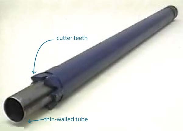
Figure 6-9 shows a pitcher barrel sampler, which combines a thin-walled tube with the ability for over-coring (see cutter teeth). The tube compresses if hard soils are encountered.
Figure 6-10: Bottom View of Piston Soil Samler
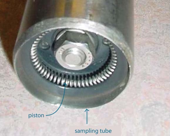
Figure 6-10 shows a piston soil sampler, which is used to retrieve discrete samples of soft silts, clays and sometimes sands from the bottom of a hole. The piston rests at the bottom of the hole and the outer sampling tube is pushed into the material being sampled. The piston prevents soil material from above the desired sampling depth from entering into the tube
There are additional types of samplers for direct push equipment including:
- sealed and unsealed single rods, and
- dual tube samplers such as:
- split-barrel,
- solid-barrel precone, and
- wire-line.
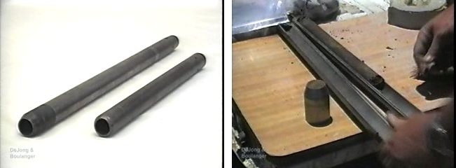
Figure 6-11: Split-Barrel Tube Sampler Closed (Left) and Open (Right)
For environmental site characterization work, rock coring is done to obtain samples of solid, fractured or weathered bedrock formations using diamond or carbide bit drilling methods. There are two main types of coring systems: conventional and wire-line (see Figure 6-12).
The wire-line method of coring is more effective than conventional rock coring because the wire-line core casing can be retrieved through the centre of the outer barrel. This differs from conventional rock coring, which involves removing the entire drill string, which is terminated with a core casing.
Wire-lines can be used for rock coring and overburden (soil) sampling.
Figure 6-12: Different Wire-Line Core Casing
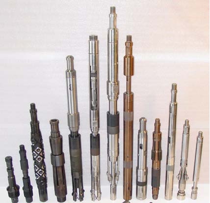
Figure 6-13: Wire-Line Rock Coring
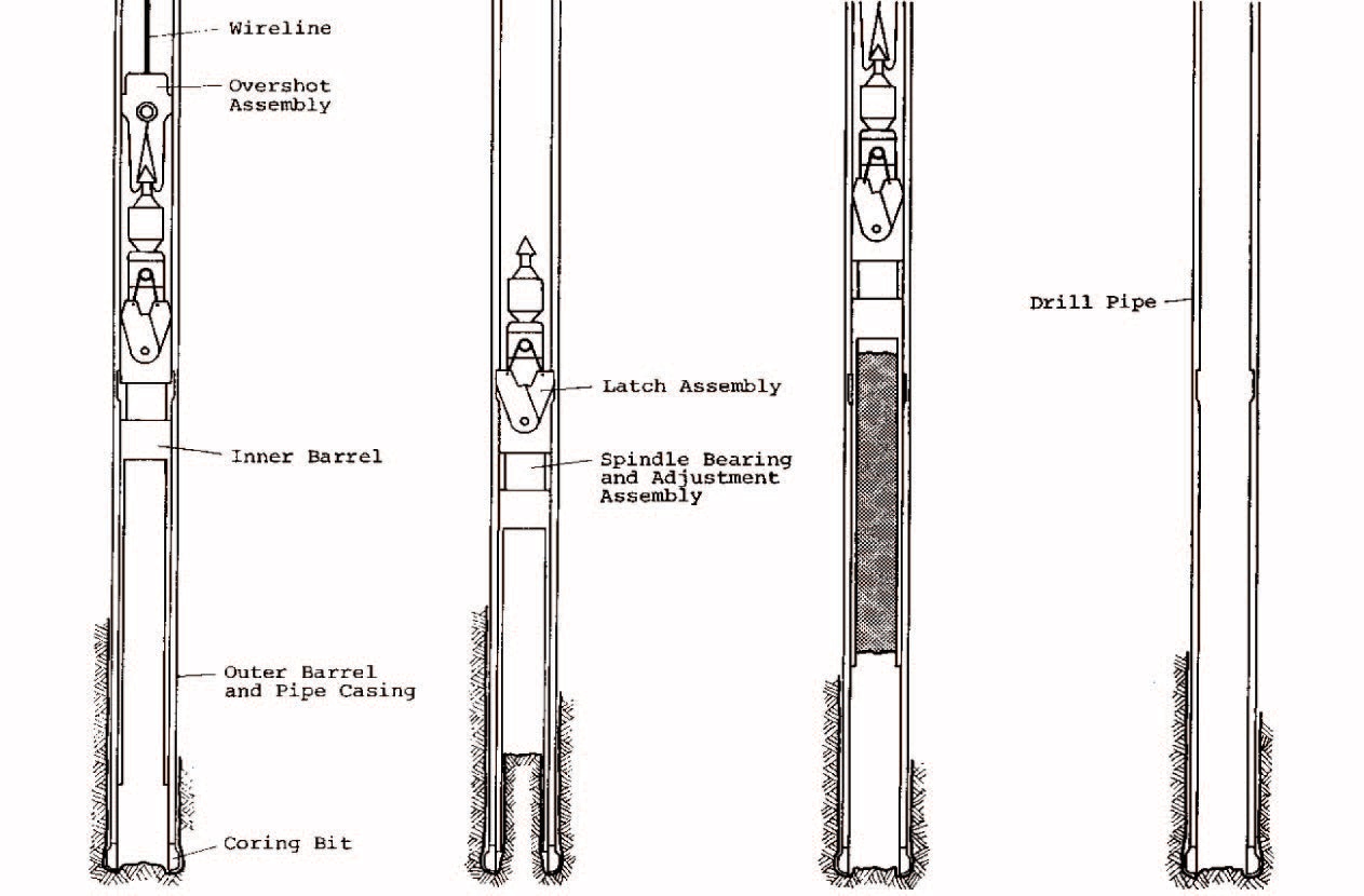
Figure 6-13 shows four cross-sections of a vertical hole.
The cross-section on the left shows an overshot assembly attached to a wireline going into the hole. The sides of the hole (or outer barrel) are supported with a pipe casing. A coring bit is attached to the bottom of the pipe casing. An inner barrel is located within the outer barrel and is attached to the overshot assembly. There is a caption below the cross-section diagram that states “Inner barrel being lowered into position”.
The second cross-section from the left shows the latch assembly at the bottom of the overshot assembly in the hole. A spindle bearing and adjustment assembly is located below the latch assembly. The sides of the hole (or outer barrel) are supported with a pipe casing. A coring bit is attached to the bottom of the pipe casing. An inner barrel is located within the outer barrel and is attached to the overshot assembly. Rock core is entering the bottom of the inner barrel. There is a caption below the cross-section diagram that states “Obtaining core, outer barrel rotating, inner barrel stationary”.
The third cross-section from the left shows an overshot assembly attached to a wireline going into the hole. The sides of the hole (or outer barrel) are supported with a pipe casing. A coring bit is attached to the bottom of the pipe casing. An inner barrel is located within the outer barrel and is attached to the overshot assembly. Rock core is located within the entire inner barrel. There is a caption below the cross-section diagram that states “Lifting inner barrel and core out of hole”.
The fourth cross-section from the left shows the sides of the hole (or outer barrel) are supported with a pipe casing. There is a caption below the cross-section diagram that states “Outer barrel and coring bit remain in hole”.
- Inner barrel being bowered into position
- Obtaining core, outer barrel rotating, inner barrel stationary
- Lifting inner barrel and core out of hole
- Outer barrel and coring bit remain in hole
Best Management Practice – Sampling Overburden (Soil) and Bedrock
Overburden and bedrock sampling protocols should consider these ASTM international standards (as amended from time to time):
- ASTM D6151 – 08 “Standard Practice for Using Hollow-Stem Augers for Geotechnical Exploration and Soil Sampling” (DOI: 10.1520/D6151-97R03)
footnote 22 - ASTM D6169 – 98(2005) “Standard Guide for Selection of Soil and Rock Sampling Devices Used with Drilling Rigs for Environmental Investigations” (DOI: 10.1520/D6169-98R05)16
- ASTM D4547 – 09, “Standard Guide for Sampling Waste for Volatile Organic Compounds” (DOI: 10.1520/D4547-09) 16
- ASTM D5434 – 09, “Standard Guide for Field Logging of Subsurface Explorations of Soil and Rock” (DOI: 10.1520/D5434-09) 16
- ASTM D6282 – 98(2005), “Standard Guide for Direct-Push Soil Sampling for Environmental Site Characterization” (DOI: 10.1520/D6282-98R05) 16
In addition, the following references will also assist in developing soil and bedrock sampling protocols:
- The Practical Handbook of Environmental Site Characterization and Ground-Water Monitoring, Second Edition
footnote 23 - Guidance on Sampling and Analytical Methods for Use at Contaminated Sites in Ontario
footnote 24 (available on Ontario.ca).
Reminder - The person constructing the well must ensure that any overburden and bedrock core samples are properly stored and disposed of to prevent any adverse effect to the natural environment.
Encountering Gas, Contamination and Water Quality Problems
The Wells Regulation requires that the person constructing the test hole or dewatering well notify the well purchaser, the owner of the land on which the well is located and the Director if natural gas is encountered.
Definition - Natural gas or other gas is a gas produced from a well that has the potential to create conditions for explosions, poisoning, fire, asphyxiation or other adverse effects at the well site, within the water distribution system connected to the well or within buildings connected to wells. Some problematic gases produced by wells in Ontario can include methane, hydrogen sulphide, propane, butane, benzene, carbon dioxide and other hydrocarbon-based gases.
It is important to be prepared for site-specific conditions, which may include soil and groundwater contamination. Indications of contamination include:
- discolouration or milky colour of the water,
- air bubbles in the water,
- sheens on the water,
- soil staining,
- unexpected or foul odours, and
- hissing or degassing sounds.
Best Management Practice – Using Gas Detection Equipment
There is a variety of direct reading instruments used for gas detection including the following:
- combustible gas indicators to measure the risk of fire and explosion, and
- oxygen deficiency meters to assess the level of oxygen in the air.
It is important that the person constructing the test hole or dewatering well be familiar with:
- gas detection equipment operation and limitations, and
- the geology and types of naturally occurring gases that may be encountered in the area.
This information may be available from well records and existing hydrogeological reports.
The person constructing the test hole or dewatering well should use gas detection equipment during any well construction in case gas is encountered.
In some cases gas may accumulate in wells after construction. In areas prone to have natural gas, the person constructing the test hole or dewatering well should use gas detection equipment at least one week after the well has been constructed as a precautionary measure. Also, any person sampling or performing work on a well in areas prone to have natural gas should use gas detection equipment.
Best Management Practice – Encountering Unexpected Contamination or Gas
If unexpected contamination or gas is encountered in the construction (including alteration) of the test hole or dewatering well, the person constructing the test hole or dewatering well should stop work immediately to reduce serious dangers to the site crew, well owner and the environment.
To meet the obligation of reporting natural gas to the Director, the person constructing the test hole or dewatering well should contact the Ministry of the Environment through the Ministry’s Spills Action Centre (SAC) at 1-800-268-6060. The SAC is available to take calls 24 hours a day, 365 days a year.
Unexpected contamination that is encountered should be reported to the Ministry of the Environment local district office and well owner.
The Ministry can offer assistance and notify other agencies to help reduce serious dangers to the site crew, well owner and the environment.
Best Management Practice – Constructing the Hole in Areas Prone to Explosive Gases
To minimize the risk of gas causing an explosion or fire, a drilling system that uses a water-based drilling fluid and other equipment may be needed to temporarily contain and control the gas during test hole or dewatering well construction (see the ‘Safety Considerations When Working on Contaminated Sites’ section in this chapter for further information). As each environment is different, the person constructing the well should seek additional advice from a Professional Geoscientist or Professional Engineer on the gas issue before starting or proceeding further with the construction of the test hole or dewatering well. The Professional Geoscientist or Professional Engineer should create a work plan for the person constructing the well that:
- identifies equipment and procedures to be used to monitor for the presence and migration of hazardous gas;
- identifies measures to be taken to prevent or reduce the likelihood of the migration of hazardous gas,
- identifies measures to be taken to prevent an adverse effect if hazardous gas is encountered,
- identifies a standard of protection that is at least equal to what is required in similar circumstances by “Oil, Gas and Salt Resources of Ontario - Provincial Operating Standards”, version 2.0, dated January 24, 2002 and published by the Ministry of Natural Resources, as amended from time to time, and
- includes a health and safety plan.
Reminder - See Chapter 15: Well Records, Documentation, Reporting & Tagging for further information on reporting natural gas or contamination.
Safety Consideration When Working On Contaminated Sites
Many tasks that are performed during well construction can be dangerous because of the associated equipment or the environment.
Knowledge of the proper operation of equipment is important at any well construction site. The person constructing the test hole or dewatering well should be experienced and knowledgeable in hazard recognition. The following information is intended to provide general suggestions only. It is important to consult company health and safety plans, Ontario Health and Safety Act and its regulations, National Institute for Occupational Safety and Health, Occupational Safety and Health Administration, ASTM International, Canadian Standards Association and other relevant safety documents when working on contaminated sites.
Before construction of the well commences, a site specific health and safety plan should be created. The safety plan should include:
- assigned safety staff (e.g. safety officers),
- a pre-assessment for safety and health hazards,
- correct personal protection equipment (PPE) such as respirators and emergency equipment that is in working order including protective clothing for :
- level A (respiratory, skin and eye protection),
- level B (respiratory protection with lower levels of skin and eye protection),
- level C (lower levels of respiratory, skin and eye protection), and
- level D (standard safety protection such as hard hat, protective boots and safety glasses),
- proper training in the use of PPE for employees,
- methods to assess exposure to persons and the environment such as air monitoring,
- standard safety procedures and rules when using all equipment,
- site control measures such as identifying personnel to work at the site, site security and establishing work zones and entry locations (includes establishing exclusion zones, contamination reduction zones and support zones at the site and procedures for persons accessing the site),
- a utility locate,
- hygiene and decontamination procedures before leaving the site,
- medical assessments prior to and after working at the site,
- procedures for medical emergencies and the proper use of emergency equipment (e.g., eye-wash station), and
- emergency response plans and contingency plans.
As part of any site safety plan, hazard identification and classification needs to take place for at least:
- electrical and other utility hazards, such as buried cables or overhead electrical wires,
- physical hazards, such as uneven terrain, caving conditions and steep grades,
- noise from machines,
- temperature due to extreme heat especially wearing chemical protective clothing or extreme cold temperatures and wind chill,
- radiation hazards,
- chemical hazards, which are commonly encountered on industrial and waste disposal sites (including gasoline, diesel and kerosene products, hypochlorite products from bleaching or pool chemicals, acids, explosives and gases such as acetylene used in welding casings),
- biological hazards,
- toxic hazards through inhalation, skin and eye contact and exposure limits, and
- confined space(s).
Encountering flammable, explosive or poisonous gases from naturally occurring or anthropogenic sources is a hazard encountered in many test holes or dewatering wells during or after construction. It has been reported that gas explosions commonly occur within 0.33 m (1′) above or below the top of the hole. Drilling equipment such as a cable tool or rotary rig presents ignition sources from friction sparking and powered machines.
Gases that are heavier than air, such as carbon dioxide (e.g. from a waste disposal site) or benzene gas (e.g., near a gasoline service station), may sink to low and confined areas potentially creating asphyxiating or hazardous conditions.
Where appropriate, to reduce the risk of explosions and other gas problems, the following should be considered:
- Air rotary rigs can reduce gas concerns in the hole by blowing fresh air into the hole using the compressor and drilling tools. The compressed air can blow the problem gas and vapours out of the hole. However, static charges or other sources of ignition can be present to ignite the gas escaping from the hole. As another precaution, introducing drilling foams into the rotary or cable tool process could reduce the risk of explosions in some cases.
- Dry ice (solid carbon dioxide) or other inert gases can be blown into the hole to displace oxygen during construction, and can reduce the risk of combustion in the hole and at the well site.
- The use of fresh air or a non-flammable gas around the hole can help reduce the risk of combustion in the top of the hole and at the well site.
- Portable ventilation devices, such as blowers with duct work, and built in grounding and bonding systems, can be used near rigs or in confined spaces to move gases and vapours away from the site.
Along with the approaches above, the person constructing the well should conduct air monitoring with proper and calibrated equipment. This includes work done at the ground surface, such as welding casings or creating other sparks near the well.
For further information on encountering and monitoring gas, see the section titled “Encountering Contamination and Water Quality Problems” on page 55 of this chapter, and the following three best management practices:
- “Best Management Practice – Using Gas Detection Equipment” (page 55),
- “Best Management Practice – Encountering Unexpected Contamination or Gas ” (page 56), and
- “Best Management Practice – Constructing the Hole in Areas Prone to Explosive Gases” (page 56).
Reminder - The following references provide further important information on safety and training for working on contaminated sites:
- NIOSH. Occupational Safety and Health Guidance for Hazardous Waste Site Activities
footnote 25 , - Nielsen. The Practical Handbook of Environmental Site Characterization and Ground-Water Monitoring: Second Edition
footnote 26 ,and - HAZWOPER, Hazardous Waste Operations and Emergency Response, Final Rule
footnote 27 .
Equipment Decontamination Considerations when Working on Contaminated Sites
Test hole or dewatering well construction equipment used on a contaminated site will come in contact with various contaminants. An effective decontamination plan will help prevent the following:
- introduction of contaminants from one site to another site,
- contamination of clean areas,
- cross-contamination between formations, including aquifers,
- cross-contamination of individual samples,
- equipment breakdown,
- accidental exposure of personnel to contaminants, and
- non-compliance with regulatory cleanup standards.
Reminder - The following standards contain procedures for equipment decontamination:
- ASTM D5088 – 02(2008) – “Standard Guide for Decontamination of Field Equipment Used at Nonradioactive Waste Sites,” (DOI:10.1520/D5088-02R08)
footnote 28 - ASTM D5608 – 01(2006) – “Standard Guide for Decontamination of Field Equipment Used at Low Level Radioactive Waste Sites,” (DOI:10.1520/D5608-01R06)
footnote 22 .
Casing
Definition - The Wells Regulation defines casing as “pipe, tubing or other material installed in a well to support its sides, but does not include a well screen.”
Casing acts to stabilize the hole, prevents unconsolidated overburden materials from entering the test hole or dewatering well, accommodates the pumping, or other equipment, and may be used to seal off or isolate unwanted formations. For the purposes of the Wells Regulation, auger flights used in the construction of a test hole or dewatering well are not considered casing.
If the test hole or dewatering well is advanced into bedrock, the person constructing the well should seat the casing into the bedrock when casing is used. See the best management practice in the “Seating and Sealing Casing into Bedrock” section of this chapter for further information.
The Wells Regulation requires that casings in new wells:
- be made of new materials unless the test hole or dewatering well is scheduled to be abandoned not later than 180 days after completion of the well’s structural stage,
- must not impair the quality of the water,
- must be watertight, and
- must be clean and free of contamination (including the removal of all visible debris and material prior to the installation of the casing in the hole).
The Wells Regulation - In addition, any casing joints and seams must be permanent and watertight. Any materials used to join casing must not impair the quality of the water.
Records of Site Condition Regulation - Starting on July 1, 2011, O. Reg. 153/04 prescribes that the provisions of the Ontario Water Resources Act and of Regulation 903 of the Revised Regulations of Ontario, 1990 (Wells) made under that Act, that would apply to a test hole but for section 1.1, and subsections 13 (2), 14.1 (2), 14.2 (3), 14.3 (2), 14.4 (4) and 14.5 (3) of that regulation, apply to a monitoring well installed for the purpose of,
- a phase one environmental site assessment; and
- a phase two environmental site assessment.
Implications for the Qualified Person
The qualified person shall ensure that phase one and phase two environmental site assessments (ESAs) are conducted in accordance with the requirement stated above.
Implications for Casing
With respect to casing material, the above requirement in O. Reg. 153/04 means that, if the new test hole is constructed and is scheduled to be abandoned not later than 180 days after the completion of its structural stage, and is to be used as a monitoring well in an ESA being conducted in support of a record of site condition, then the new casing material exemption does not apply and the casing must be made of new material.
Reminder - The above requirement in O. Reg. 153/04 also affects obligations such as well screen, shallow works and annular space size and filling for monitoring wells. See the Well Screen Design for Test Holes and Dewatering Wells section in this chapter, Chapter 3: Exemptions: Wells, Activities & Experienced Professionals and Chapter 7: Annular Space & Sealing for further information.
Records of Site Condition Regulation - Please refer to O. Reg. 153/04 for RSC requirements.
Reminder - For clarification on the term “monitoring well” in the Records of Site Condition regulation see Chapter 2: Definitions & Clarifications, Table 2-2.
Best Management Practice – Cleaning Casing
To remove substances such as: cutting oils, solvents, lubricants, waxes and other chemical residues from the casing, the person constructing the well should follow ASTM D5088 – 02(2008) – “Standard Guide for Decontamination of Field Equipment Used at Nonradioactive Waste Sites
Exemption from the Requirement to Case the Test Hole or Dewatering Well
The Wells Regulation - A test hole or dewatering well is not required to be cased if:
- abandonment of the test hole or dewatering well is scheduled to take place not later than 30 days after completion of the structural stage of the test hole or dewatering well, and
- the person constructing the well covers the upper open end of the well securely in a manner that is sufficient to prevent the entry of surface water and other foreign materials whenever the well is left unattended.
Reminder - See “Best Management Practices – Covering Test Holes or Dewatering Wells Without Casing” on page 47 of this chapter for further guidance on covering an uncased test hole or dewatering well.
Examples of uncased test holes include:
- Test pits for observation of soil and groundwater properties at waste disposal sites
- Test holes where only the hollow-stem auger flights are holding the hole open temporarily for identification of soil and groundwater properties (see Figure 6-27 and Figure 6-29 of this chapter)
- Diamond drilled test holes completed into sedimentary bedrock formations to determine quality of aggregate and location of groundwater
Best Management Practice – Obtaining Written Contract for Uncased Test Holes and Dewatering Wells
In the case where the person constructing the well is not also retained to abandon the uncased test hole or dewatering well within 30 days, then the person constructing the well should have a signed written contract with the well purchaser and, if not the same, the well owner, that indicates the well owner has agreed to abandon the well in accordance with the Wells Regulation not later than 30 days after the completion of the structural stage of the test hole or dewatering well. The written contract will help protect the interests of the person constructing the well if the completed uncased test hole or dewatering well is not abandoned within 30 days and will advise the well owner of this requirement.
Best Management Practice – Abandon Uncased Test Hole or Dewatering Well
As soon as samples, measurements, pumping, or observations have been completed and no further pumping or observations are scheduled, the well should immediately be properly abandoned (plugged and sealed). If the well is abandoned, the person abandoning the well (often the well owner) must ensure the test hole or dewatering well is abandoned in accordance with the Wells Regulation and as outlined in Chapter 17: Abandonment: How to Plug & Seal Test Holes & Dewatering Wells.
The regulatory exemptions regarding casing test holes and dewatering wells allow for well technicians, engineers and geoscientists to use their professional expertise to design and install test holes and dewatering wells on a case by case basis, thereby enabling the testing, sampling or dewatering of various groundwater intervals.
Persons using such professional judgement and the well owner should be aware of the following requirement:
If the well acts as a pathway for the movement of:
- natural gas,
- contaminants, or
- other materials
between subsurface formations (including aquifers) or between the ground surface and a subsurface formation and where the movement may impair the quality of the waters, the person abandoning the well, often the well owner, must do one of the following:
- take measures to prevent the movement of the above materials and ensure the measures are functional at all times, or
- immediately abandon the well.
This Wells Regulation requirement prescribes that, at all times, steps must be taken by the well owner to prevent the test hole or dewatering well from acting as a pathway for contaminants that may impair groundwater resources.
Reminder - Further information on abandonment requirements is provided in Chapter 16: Abandonment: When to Plug & Seal Test Holes & Dewatering Wells and Chapter 17: Abandonment: How to Plug & Seal Test Holes & Dewatering Wells.
Best Management Practice – Using Temporary Casing in Uncased Test Hole or Dewatering Well
Temporary steel casing, including hollow-stem auger flights, should be used during the construction of an uncased well. The temporary casing should have sufficient strength to not collapse or break during construction. Advancing a proper temporary casing during the construction of the hole reduces the risk of:
- Contaminants in a groundwater zone migrating vertically through the hole and intermingling with other fresh groundwater zones. The intermingling may impair clean groundwater zones and cause a negative bias in a water quality sample result.
- Formation collapse into the hole.
Formation collapse may present the following issues:
- In certain formations (e.g. flowing sand), creating an uncased hole may pose a safety hazard to personnel, equipment and the public as caving conditions may develop
- If collapsed material is disturbed, it may cause a preferential pathway (e.g. for contaminants)
- Collapsed material could complicate well abandonment, as collapsed material is not an accepted abandonment barrier material
Best Management Practice – When Contaminants Are Present in an Uncased Test Hole or Dewatering Well
The person constructing the well should not install an uncased well through a source of contaminants or a plume of contaminants. Contaminants in a groundwater zone can migrate through the hole and intermingle with fresh groundwater zones and other subsurface formations. The intermingling may impair clean groundwater zones requiring the well owner to:
- immediately abandon the well, or
- take measures to prevent the movement and ensure the measures are functional at all times.
Best Management Practice – Avoiding Flowing Well Conditions in an Uncased Test Hole or Dewatering Well
The person constructing the test hole or dewatering well should not create an uncased well through an area prone to flowing well conditions. Groundwater discharging from a flowing test hole or dewatering well could cause one or more of the following:
- Flooding conditions, erosion and other property damage
- Contaminants to discharge to the surface that may cause an adverse effect to the natural environment
- A change in groundwater gradients causing the plume of contaminants to move in an unwanted direction
- Unexpected and significant expenses to meet the Wells Regulation’s flowing well construction requirements or abandonment requirements
Reminder - The person constructing the test hole or dewatering well should follow the best management practices and information found in Chapter 11: Flowing Test Holes & Dewatering Wells when a well is constructed in an area prone to flowing conditions.
Casing Materials
The Wells Regulation exempts test holes and dewatering wells from the casing material specifications (e.g. nominal thickness). This exemption allows well technicians, engineers and geoscientists to use their professional expertise to design and install test holes and dewatering wells on a case by case basis using alternative materials. It is important that any casing material be able to withstand the stress and weight of the formation with depth, any corrosive properties of the formation and groundwater, and seasonal changes such as freezing and thawing.
Choosing the test hole or dewatering well casing material that is best for the specific situation includes consideration of the:
- Physical strength
- Resistance to the chemical composition of the groundwater and formation
- Possible interference with analytical sample results
- Purpose for the test hole or dewatering well
- Formation characteristics
- Production capacity of the aquifer for dewatering or conducting pumping tests
- Potential contamination (chemical or biological) in the groundwater
- Water uses planned for the well
- Size of the hole.
Table 6-6 on page 67 of this chapter, describes the advantages and disadvantages of various well casing materials used in the construction of test holes or dewatering wells. Once determined and installed, the type, depth and specifications of the casing used must be recorded on the well record.
Reminder - For information on design components of well casing refer to Chapter 10 of The Practical Handbook of Ground-Water Monitoring
Reminder - Chapter 10 of The Practical Handbook of Ground-Water Monitoring provides information on well casing strength, chemical composition and other physical properties needed to determine what type of casing is appropriate for each specific site.
Reminder - For information on cleaning casing see the best management practice “Cleaning Casing” on page 61 of this chapter.
| Material | Characteristics | Advantages | Disadvantages |
|---|---|---|---|
Thermal plastic – PVC 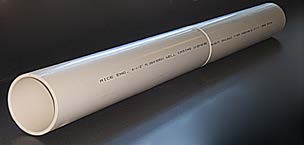 |
|
|
|
Steel 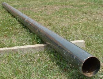 |
|
|
|
Stainless Steel 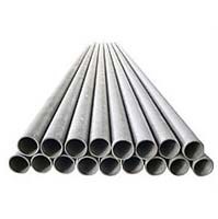 |
|
|
|
Concrete (mostly used in dewatering wells) 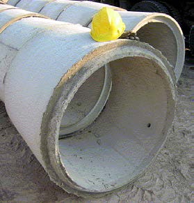 |
|
|
|
ABS (Plastic) 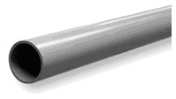 |
|
|
|
Fibreglass (mostly used in dewatering wells) 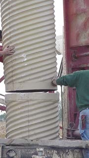 |
|
|
|
Galvanized Steel (mostly used in dewatering wells) 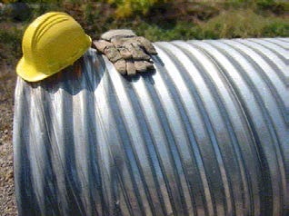 |
|
|
|
Reminder - There are many factors that affect the casing selection including depth of the well and water quality.
Reminder - Some materials such as ABS, polytetrafluoroethylene (PTFE) (e.g. Teflon), fiberglass and glass are not typically used for casing for test holes and dewatering wells. It is important to refer to manufacturer’s specifications and other information to determine if the material is appropriate for use in test holes and dewatering wells at a specific site.
Reminder - A downhole video camera should be used to inspect the casing, casing joints, the seal between the screen and casing and the sealing of the bottom of the casing into competent bedrock for permanent dewatering wells of sufficient diameter (e.g. 15 cm (6″) or greater).
Best Management Practice – Proper Use of a Large Diameter Fibreglass Casing
It is the responsibility of the well technician to ensure that larger diameter fibreglass casing typically used in a dewatering well is appropriate for the geologic environment and well depth. It is important that persons constructing larger diameter wells consult with the manufacturers who make fibreglass casing for wells. To reduce the risk of well casing collapse, the fibreglass manufacturer should recommend a casing design for the installation. It is important that the person constructing the well then follow the manufacturer’s recommendations.
Best Management Practice – Proper Use of a Concrete Casing
The person constructing the test hole or dewatering well with concrete casing should consider using concrete tiles designed to ASTM C478 – 13 – “Standard Specification for Precast Reinforced Concrete Manhole Sections
The structure of the concrete tiles should be sufficient to prevent well collapse.
Concrete tiles should be carefully and evenly backfilled on the outside to ensure the tiles remain plumb.
Seating and Sealing Casing into Bedrock
Test holes and dewatering wells are exempt from the requirement to seal the casing into the bedrock. This allows a test hole or dewatering well to take water from an overburden aquifer and a bedrock aquifer. As well, this allows for certain dedicated multi-level groundwater systems to take water samples from multiple overburden and bedrock formations and the overburden/bedrock interface.
Best Management Practice – Seating and Sealing Casing into Bedrock
Where a test hole or dewatering well is obtaining groundwater from the bedrock, the casing should be properly seated and sealed into the bedrock to prevent overburden materials from migrating under the casing into the test hole or dewatering well.
Examples of properly sealing the well casing into the bedrock include:
- seating the bottom of the well casing with a drive shoe into competent bedrock below the top of the overburden/bedrock interface,
- placing a bentonite or a cement product, that is suitable for the environment, in the annular space at the overburden/bedrock interface, and
- a combination of seating the bottom of the well casing and placing a bentonite or cement product in the annular space at the overburden/bedrock interface.
The following methods can be used to confirm that the casing is sealed in the bedrock:
- downhole video camera for visual confirmation, and
- hydraulic packer testing.
Reminder - See Chapter 8: Multi-Level Monitoring Test Holes for well designs that can obtain groundwater samples and measurements from discreet zones in overburden, weathered bedrock and bedrock formations
Joining Casing Lengths
Well Casing Joints for New Test Holes and Dewatering Wells
The Wells Regulation - Joints in casing are not allowed, unless the joints:
- achieve a permanent, watertight bond, such as welded steel joints, and
- are made so that the jointed casing does not impair the quality of water with which it comes in contact.
Joints for Concrete Casing in New Test Holes and Dewatering Wells
The Wells Regulation - If the casing is concrete;
- it must be fully cured and commercially manufactured,
- the concrete sections must be properly aligned so the joints are flush and the casing is centred and plumb, and
- the sections must be joined with a mastic sealing material (typically butyl rubber material) that remains pliable and waterproof and is approved for potable water use by NSF International Standard - NSF 61.
After the concrete casing length has been attached, additional sand/cement mortar mixes could also be placed on the outside of the casing joint area to help seal the joint.
Best Management Practice – Proper Joining of Concrete Casing
All concrete tile joints should be designed to ASTM C990–09 titled “Standard Specification for Joints for Concrete Pipe, Manholes, and Precast Box Sections Using Preformed Flexible Joint Sealants”.
Reminder - For unsealed joints in concrete tiles used as well screens see the section
Well Screens Using Large Diameter Concrete Tiles of this chapter.
Reminder - Table 6-7 provides suggestions and photographs for achieving watertight joints. Table 6-8 and Table 6-9 provide further information on the methods for sealing a joint and some advantages and disadvantages.
Reminder - Even though Table 6-7 provides suggestions for joining casing and Table 6-8 and Table 6-9 provide advantages and disadvantages, the person constructing the test hole or dewatering well should determine the type of bond used to seal the joint, or if the casing should even have joints, depending on the test hole or dewatering well design, environmental conditions and formations.
Reminder - It is important to follow the manufacturer’s specifications regarding how to create permanent watertight joints between casing sections. Table 6-7 provides some suggestions for achieving permanent watertight joints.
| Casing Type | Method for Achieving Permanent Watertight Joints |
|---|---|
| Plastic |
Types of joints:
For PVC, use O-ring on male thread as per ASTM F480 - 06be1 “Standard Specification for Thermoplastic Well Casing Pipe and Couplings Made in Standard Dimension Ratios (SDR), Schedule 40 and Schedule 80 F480–06B For ABS use ABS primer and glue that is approved for potable water use by the NSF International |
PVC and Solvent Cement (certain environments – must not impair the quality of the water with which they come in contact). 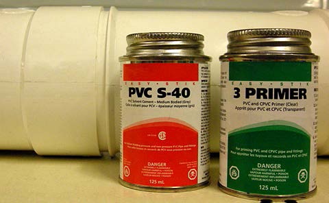 |
PVC – O-Ring (no solvents used) 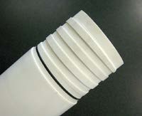 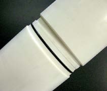 PVC – Threaded (no solvents used) PVC – Threaded (no solvents used) 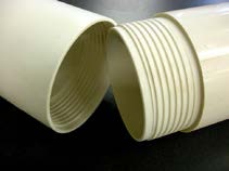 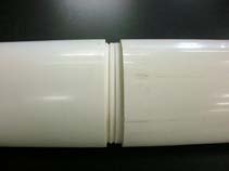 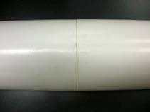 |
| Steel Casing |
Types of joints:
When welding, use appropriate welding rod for creating the casing joints Steel Casing – Welded Using Three Passes
Steel Casing – Threaded
|
| Concrete |
|
Roll of Mastic Sealant 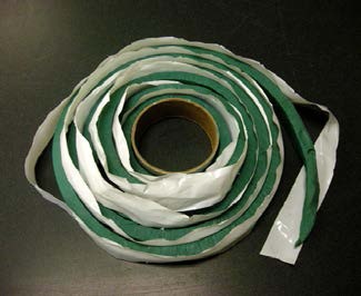 |
Mastic Sealant Placed on Concrete Tile Joint – Open
Two Tiles Sealed Together with Mastic Sealant
|
| Fibreglass Casing for Large Diameter Dewatering Wells | Joined by “bell and spigot” joint. The casing sections are attached with screws and also sealed with an epoxy. The epoxy must be a material that does not impair the quality of the well water. |
|
|
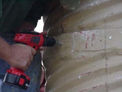 |
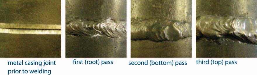
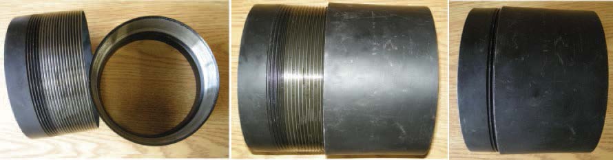
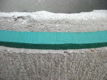
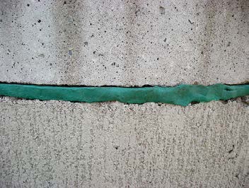
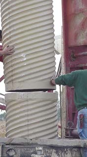
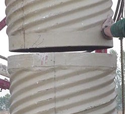
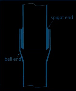
Best Management Practice – Joining Sections of PVC Casing
When joining sections of PVC casing a person constructing a well should follow ASTM Standard Specification for Thermoplastic Well Casing Pipe and Couplings Made in Standard Dimension Ratios (SDR), Schedule 40 and Schedule 80, ASTM Standard F 480, ASTM, West Conshohocken, PA, 2004u.
| Type | Method | Advantages | Disadvantages |
|---|---|---|---|
Threaded Connections –
|
Sections are joined together by twisting. Wrapping the threads with fluoropolymer tape prior to joining sections improves the watertightness of the joint. Because all joints in a test hole or dewatering well casing must be watertight, it is important that the extent to which the joints are tightened comply with recommendations of the manufacturer. Where the annular space is minimal, threaded or other couplings should not be used to attach well screens to casing or lengths of casing together. Casings that do not use couplings are best suited for use in test hole or dewatering well construction. |
Casing with threads machined or moulded directly onto the pipe (without use of larger-diameter couplings) provides a flush joint between both inner and outer diameters. |
As most manufacturers have their own thread type, threaded casing may not be compatible between manufacturers. If the threads do not match and a joint is made, the joint can fail or leak either during or after casing installation. This could result in the following problems:
|
| Type | Method | Advantages | Disadvantages |
|---|---|---|---|
| Welding Via Application of Heat | Casing can either be butt welded or welded using a weld ring. In either case, three passes are made (see image in Table 6-7) It is important that the person welding be aware of proper welding techniques and welding safety. |
May produce joints that are stronger than the casing and enhance the tensile strength of casing string. |
Greater assembly time. |
| Threaded Joints | Sections are joined together by twisting. Wrapping the threads with fluoropolymer tape prior to joining sections improves the watertightness of the joint |
Inexpensive, fast and convenient connections. |
Tensile strength at the threaded joint of the casing string is reduced to approximately 70 percent of the casing strength. This reduction in strength typically poses a problem for larger diameter wells. |
Casing Accessories
Table 6-10 provides details on the most common casing accessories
| Casing Accessory | Characteristic | Graphics |
|---|---|---|
| Drive Shoes |
|
Rotary Drive Shoe
Cable-Tool Drive Shoe |
| Weld Rings |
|
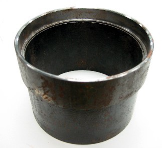 |
| Casing Centralizers |
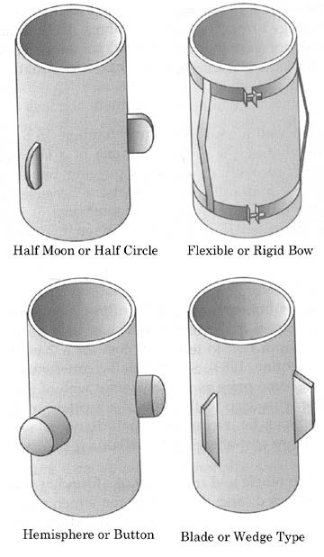 |
|
| Breakaway Guide |
|
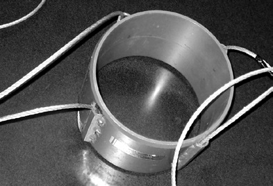 |
| Shale Trap |
|
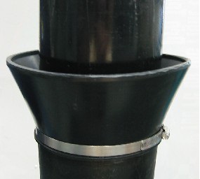 |
| Tri Seal / K-Packer |
|
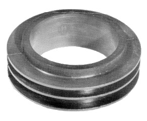 |
| Examples of casing for drilled wells with different wall thicknesses |
|
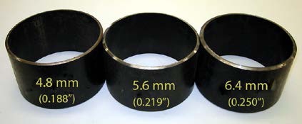 |
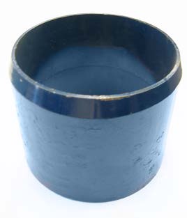
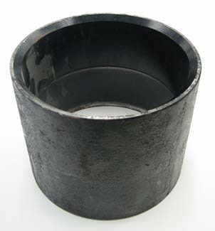
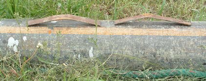
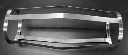
Casing Installation Techniques
Casing is installed using one of two techniques:
- Forcing – the forcing techniques include driving, jacking, pushing and rotation.
- Lowering – into an over sized hole or hollow-stem auger.
Reminder - Safety Note: Extreme care should be used when handling a long string of casing. In deep wells (e.g., 200 m) this is a significant concern for lighter casing materials (e.g., PVC). Devices that require tension alone to hold and secure casing, such as slings and chains, should not be used. Instead, it is advisable to use proper casing elevators.
Centering the Casing
During installation, it is important to ensure casing is centred in the test hole or dewatering well.
Proper centering and alignment of the casing in a hole will create an appropriately sized annular space that is consistent around the entire well casing. An appropriately sized annular space allows for even placement of filter pack materials and sealant (grout) around the casing and well screen.
Best Management Practice – Centering the Casing
For centering casing in drilled wells, it is important to use and properly attach centralizer devices to the outside of the casing. It is important that centralizer devices are made of material that will not impair the quality of the water.
General Guidelines for Using the Breakway Guide
A breakaway guide (Figure 6-14) may be used to centre the casing in a test hole or dewatering well constructed by a cable tool drilling rig. The use of a breakaway guide will allow the person constructing the well with a cable tool rig to create a smaller diameter annular space (minimum of 5.1 cm greater than the outer diameter of the casing versus a minimum of 7.6 cm) for a test hole or dewatering well that is not scheduled to be abandoned within 180 days of the completion of the well’s structural stage.
The minimum hole size requirement does not apply to a new test hole or dewatering well that is scheduled to be abandoned within 180 days of the completion of the well’s structural stage.
Reminder - For additional information on minimum hole size and annular space requirements see Table 6-4 in this chapter.
Records of Site Condition Regulation - Starting on July 1, 2011, O. Reg. 153/04 prescribes that the provisions of the and of Regulation 903 of the Revised Regulations of Ontario, 1990 (Wells) made under that Act, that would apply to a test hole but for section 1.1, and subsections 13 (2), 14.1 (2), 14.2 (3), 14.3 (2), 14.4 (4) and 14.5 (3) of that regulation, apply to a monitoring well installed for the purpose of,
- a phase one environmental site assessment; and
- a phase two environmental site assessment.
Implications for the Qualified Person
The qualified person shall ensure that phase one and phase two environmental site assessments (ESAs) are conducted in accordance with the requirement stated above.
Implications for the Size of the Hole
With respect to the allowance for the size of the hole to be at least 5.1 cm greater than the outer diameter of the casing, the above requirement in O. Reg. 153/04 means that, if the new test hole is constructed using cable tool equipment and is scheduled to be abandoned not later than 180 days after the completion of its structural stage, and is to be used as a monitoring well in an ESA for a record of site condition, then a breakaway guide must be attached 2 m (6.3′) above the bottom of the casing.
Reminder - The above requirement in O. Reg. 153/04 also affects obligations such as casing material, annular space sealing, well screen material and shallow works for monitoring wells. See the “Casing Material” and “Well Screen Design for Test Holes and Dewatering Wells” sections in this chapter, Chapter 3: Exemptions: Wells, Activities & Experienced Professionals and Chapter 7: Annular Space & Sealing for further information.
Records of Site Condition Regulation - Please refer to O. Reg. 153/04 for RSC requirements.
When using these breakaway guides, the person constructing the well should:
- Install the working (also called starter or surface) casing as plumb as possible into the hole. The working casing should be used to collar the hole and create a hole that is at least 5.1 cm (2″) or greater than the outside diameter of the permanent casing
- Ensure that the drill string is centred in the hole.
- Place the breakaway centralizer guide over the first section of permanent casing so that it is 2 m (6.6′) above the bottom of the first permanent casing.
- Install the permanent casing into the well. The breakaway guide is held by cable hooks that rest on the top of the working casing.
- If required, hold the permanent casing at the top with a casing elevator. Drilling the open hole out the bottom of the first permanent casing should continue until the open hole begins to collapse [e.g. 1 – 3 m (3.3 – 6.6′)].
- Weld a second length of casing to the first permanent casing.
- Pull out the breakaway centralizer guide using the cables and hooks.
- Fill the annular space with suitable sealant (see Chapter 7: Annular Space & Sealing).
- Continue drilling and advancing casing sections while keeping the sealant (grout) column in the annular space topped up to ground surface during well construction.
- Pull the working casing and top up sealant (grout) to the ground surface when the well is finished.
Figure 6-14 shows a cross-section diagram of this process. The diagram uses the example of a well that is greater than 6 m deep and has a hole diameter (created by the outside diameter of a working casing) slightly greater than the minimum requirement of 5.1 cm larger than the finished permanent casing.
Reminder - All figures and diagrams are for illustrative purposes only, are not to scale and do not necessarily represent full compliance with other requirements found in the Wells Regulation.
Figure 6-14: Example of the Use of a Breakaway Centralizer Guide with a Cable Tool Rig
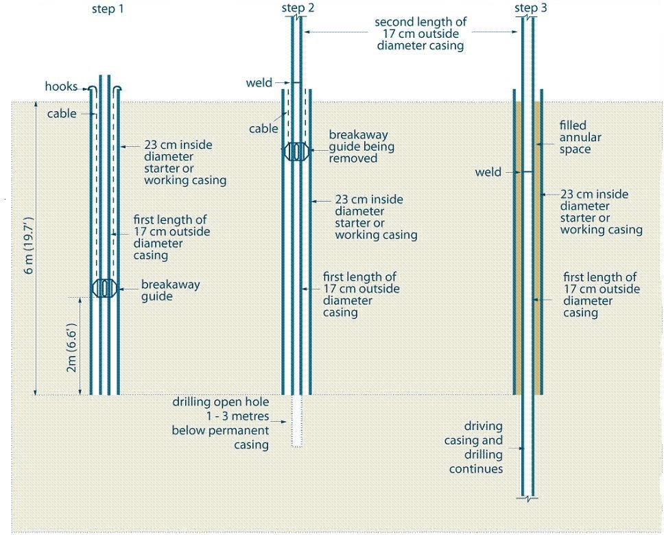
Figure 6-14 shows a cross-sectional diagram of the installation of a breakaway centralizer guide in a drilled well. Figure 6-14 shows three steps.
The first step (Step 1) is shown on the left side of the diagram. Step 1 shows a vertical hole that extends 6 metres (19.7 feet) into the subsurface. A starter (or working) casing with an inside diameter of 23 centimetres (9.1 inches) has been placed in the vertical hole. The starter casing extends from above the ground surface to 6 metres (19.7 feet) into the hole below the subsurface. The vertical hole has a length of permanent inner casing with an inside diameter of 17 centimetres (6.7 inches). The permanent inner casing is located within the starter casing. The permanent inner casing extends from above the ground surface to 6 metres (19.7 feet) into the subsurface. A breakaway guide is attached to the outside of the permanent inner casing and extends to the side of the starter casing. The breakaway guide is located about 2 metres (6.5 feet) above the bottom of the permanent inner casing. Hooks are attached to the top of the starter casing. Two cables extend from the hooks to the breakaway guide.
The second step (Step 2) is shown in the centre of the diagram. Step 2 shows a vertical hole extending 7 to 10 metres (23 to 32.8 feet) into the subsurface. A starter (or working) casing with an inside diameter of 23 centimetres (9.1 inches) has been placed in the vertical hole. The starter casing extends from above the ground surface to 6 metres (19.7 feet) into the hole below the subsurface. The vertical hole has two sections of permanent inner casing with an inside diameter of 17 centimetres (6.7 inches). Below the ground surface, the permanent inner casing is located within the starter casing. The permanent inner casing extends from above the ground surface to 6 metres (19.7 feet) into the subsurface. The joint between the second and first length of permanent inner casing is located above the ground surface. The joint between the two permanent inner casing sections has been welded. A breakaway guide is shown attached to the outside of the permanent inner casing and extends to the side of the starter casing. The breakaway guide has been raised from its location in Step 1 to just below the ground surface. Hooks are attached to the top of the starter casing. Two cables extend from the hooks to the breakaway guide. An open hole has been drilled 1 to 3 metres (3.3 to 9.8 metres) below the bottom of the casing.
The third step (Step 3) is shown on the right side of the diagram. Step 3 shows a vertical hole extending greater than 10 metres (32.8 feet) into the subsurface. A starter (or working) casing with an inside diameter of 23 centimetres (9.1 inches) has been placed in the vertical hole. The starter casing extends from above the ground surface to 6 metres (19.7 feet) into the hole in the subsurface. The vertical hole also has the two sections of permanent inner casing with an inside diameter of 17 centimetres (6.7 inches). Below the ground surface, the permanent inner casing is located within the starter casing. The permanent inner casing extends from above the ground surface to the bottom of the hole in the subsurface. The joint between the second and first sections of permanent inner casing is shown below the ground surface. The joint between the two permanent inner casing sections has been welded. The breakaway guide has been removed from the well. The annular space between the permanent inner casing and the starter casing has been filled with a suitable sealant.
- The first weld is made to pass through the casing centralizer guide.
- The casing in step 2 is held in place by the se of an elevator
- The starter or working casing is removed before the structural stage of the well is complete.
- The outer diameter of the starter, or working, casing makes the hole diameter at least 5.1cm(2") greater than the permanent casing.
- See the previous page for the requirements and additional information.
Reminder - This figure is not to scale, it is for illustrative purposes for this chapter only, and does not necessarily represent full compliance with the requirements found in the Wells Regulation.
Test Hole or Dewatering Well Screens
To prevent water bearing formation collapse into the well and significantly reduce sediment or particles in the well water, it is important to install a well screen in all unconsolidated formations, in most semi-consolidated formations and sometimes in bedrock.
Definition - The Wells Regulation defines a well screen as perforated pipe or tubing, unsealed concrete tiles or other material installed in a well to filter out particulate matter and form the water intake zone.
The Wells Regulation requires that well screens for new wells must be made of new materials that are clean and contaminant free. Well screen material is not required to be new for new test holes and dewatering wells that are scheduled to be abandoned not later than 180 days after completion of the structural stage. The well screen materials must not impair the quality of the water.
Records of Site Condition Regulation - Starting on July 1, 2011, O. Reg. 153/04 prescribes that the provisions of the Ontario Water Resources Act and of Regulation 903 of the Revised Regulations of Ontario, 1990 (Wells) made under that Act, that would apply to a test hole but for section 1.1, and subsections 13 (2), 14.1 (2), 14.2 (3), 14.3 (2), 14.4 (4) and 14.5 (3) of that regulation, apply to a monitoring well installed for the purpose of,
- a phase one environmental site assessment; and
- a phase two environmental site assessment.
Implications for the Qualified Person
The qualified person shall ensure that phase one and phase two environmental site assessments (ESAs) are conducted in accordance with the requirement stated above.
Implications for Well Screen for New Test Holes
With respect to well screen material, the above requirement in O. Reg. 153/04 means that, if the new test hole is constructed and is scheduled to be abandoned not later than 180 days after the completion of its structural stage, and is to be used as a monitoring well in an ESA for a record of site condition, then the new well screen material exemption does not apply and the well screen must be made of new material.
Reminder - The above requirement in O. Reg. 153/04 also affects obligations such as casing, shallow works and annular space size and filling for monitoring wells. See the Casing Material section in this chapter, Chapter 3: Exemptions: Wells, Activities & Experienced Professionals and Chapter 7: Annular Space & Sealing for further information.
Reminder - For clarification on the term “monitoring well” in the Records of Site Condition regulation see Chapter 2: Definitions & Clarifications, Table 2-2.
Best Management Practice – Cleaning Well Screens
ASTM D5088 – 02(2008) – “Standard Guide for Decontamination of Field Equipment Used at Nonradioactive Waste Sites
Where chlorinated water will not react with compounds in the groundwater, well screens and filter packs should be disinfected by following the instructions found in the most recent version of the American Water Well Association Standard C654 titled Disinfection of Wells.
Well screens that are permitted for use in test holes or dewatering wells are as follows:
- commercially manufactured well screens,
- casings that are slotted or perforated to create well screens, and
- concrete casings with unsealed joints to create well screens (see “Best Management Practice – Groundwater Entering Large Diameter Wells Cased with Concrete Tiles” on page 100 of this chapter).
Best Management Practice – Using Clean Pre-Packaged Well Screens
A clean, commercially manufactured pre-packaged well screen that is designed for the formation where the screen will be placed, should be purchased and installed to prevent unconsolidated fines from entering the well and thus creating a hydraulically efficient well.
Reminder - To prevent casing and formation collapse, the person constructing the test hole or dewatering well should contact the manufacturer of casing before creating a well screen by perforating or slotting the casing.
Best Management Practice – Using New Well Screens
New well screen materials should be used in all test holes and dewatering wells where a well screen is installed, (as opposed to re-using a well screen from another well), to reduce the risk of cross-contamination between wells.
Well Screen Design for Test Holes or Dewatering Wells
Selecting Well Screen Material
Casing and well screen material compatibility should be carefully considered when selecting well screen material.
Best Management Practice – Designing a Well Screen
Guidance on well screen and filter pack design for test holes can be found in ASTM D 5092-04e1 – “Standard Practice for Design and Installation of Ground Water Monitoring Wells
Further guidance on well screen and filter pack design for dewatering wells can be found on pages 279 to 291 of Construction Dewatering and Groundwater Control
High density polyethylene (HDPE) well screens can be used for shallow dewatering wells in contaminated environments where PVC is not compatible. Manufacturer’s specifications and other information should be consulted to determine if HDPE is appropriate for a particular project (e.g., may deform at depth)
Well screens for non-vertical or directional dewatering wells are subject to additional stresses and as such the material chosen needs to be very strong. HDPE may be an appropriate choice for directional wells because this material is strong, flexible, resistant to many chemicals, and can handle the stresses.
In some situations, multiple screens can be separated by sections of casing. These systems are commonly known as multi-level monitoring wells. These systems require separate zones of sealant material to separate the different well screens and filter packs or ports. For additional information see Chapter 8: Multi-level Monitoring Test Holes.
Well Screen Slots, Lengths and Diameter
Well screen openings (or slots), screen length, and diameter are all selected to allow water to pass through a screen with the least friction, keep out aquifer formation material and serve as a structural support for the test hole or dewatering well. Figure 6-15 shows a sample of a manufactured telescopic well screen. Telescopic well screens are designed to be pushed out the bottom of the casing. Other well screens are attached to the bottom of the first length of the casing.
Manufactured well screens are made of many materials including steel and plastic. The slots in the well screens may be designed as continuous, louvered, bridged, milled (vertical) and slotted plastic. Table 9.15 on page 398 of Groundwater & Wells: Third Edition
Under certain circumstances and when properly installed, plastic well screens provide test holes or dewatering wells with adequate structural strength, good hydraulic characteristics, and long life. To prevent the impairment of the well water and aquifer as required by the Wells Regulation, plastic well screens should be approved for potable water use. To ensure sufficient structural strength, the screen manufacturer should be contacted for recommended wall thicknesses when plastic well screens are used.
Manufactured continuous-slot screens have larger open areas compared to the other types of screens. Smaller openings reduce yield, increase drawdown and make well development difficult. Continuous-slot openings are also V-shaped in design. The V-shaped opening allows the open area to widen into the screen. This slot design reduces clogging from elongated or oversized particles.
To ensure optimum use, the well screen entrance velocity needs to be calculated to prevent friction loss and increased rates of encrustation and corrosion.
Best Management Practice – Recommended Maximum Entrance Velocity for Well Screens
It is important that the screen should have a maximum entrance velocity that does not exceed 0.03 metres per second (or 0.1 foot per second) to reduce friction loss and rates of encrustation and corrosion.
Table 18.2 on page 283 of Construction Dewatering and Groundwater Control: New Methods and Applications, Third Edition
The size of the screen slots is determined based on an analysis of the aquifer formation materials. The screen slot size is matched to the grain size distribution of the aquifer formation.
The function of the slot size is important in the well screen. Small openings limit well yield while large openings may not prevent the fine material from entering the well. As a general rule, the slots are sized as shown below in the criteria for selecting a well screen for a drilled well. Then the formation is developed around the well screen to remove the fines through the screen, leaving the coarser material around the outside of the well screen slots.
Criteria for selecting a well screen include:
- Large percentage of open area
- Generally, where the uniformity coefficient (see definition below) is:
- >6, the slot size needs to retain no less than 50% of the formation material
- 3 to 6, the slot size needs to retain no less than 60% of the formation material
- <3, the slot size needs to retain between 70% and 90% of the formation material
- Length of screen
- Planned yield of the well
- Non–clogging slots
- Resistance to corrosion
- Sufficient column and collapse strength
- Ease of well development
- Low potential for encrustation in the formation
- Low head loss through the screen
- Prevention of formation collapse during development and when pumping the well
Reminder - Uniformity coefficient is the ratio of the sieve size that retains 40% of the formation material (passes 60% = D60) to the sieve size that retains 90% (passes 10% = effective size)
The Wells Regulation - In cases where a new well with a well screen is constructed by a method other than digging or by the use of a driven or jetted point, the annular space shall be filled with clean, washed gravel or sand:
- from the bottom of the well screen to at least the top of the well screen, and
- not closer than six metres to the ground surface, unless the only useful aquifer available necessitates a shallower well, in which case the top of the gravel or sand shall not be closer than 2.5 metres to the ground surface.
Where a well screen is placed in a shallow aquifer (i.e. < 6 m deep), the depth of the new test hole or dewatering well must be such that the top of the gravel or sand in the annular space will not be closer than 2.5 metres to the ground surface.
This requirement applies to a test hole or dewatering well constructed by a drilling or boring method unless otherwise exempt, as discussed below:
The Wells Regulation - The depth requirement for the top of the sand and gravel layer does not apply if the new test hole or dewatering well is scheduled to be abandoned not later than 180 days after completion of its structural stage.
The depth requirement for the top of the sand and gravel layer does not apply if the well is constructed with a casing surrounded by a larger permanent outer casing (sometimes referred to as a double walled casing).
Reminder - The depth requirement for the top of the sand and gravel layer also does not apply to wells constructed by digging or by the use of a driven or jetted point.
Reminder - See Chapter 7: Annular Space & Sealing and Chapter 8: Multi-Level Monitoring Test Holes for further information on requirements for a casing surrounded by a permanent outer casing.
Records of Site Condition Regulation - Starting on July 1, 2011, amendments to O. Reg. 153/04 came into force and apply to phase two environmental site assessments (ESAs) conducted in support of records of site conditions (RSCs). For any such RSC submitted on or after this date, where a groundwater sampling method is to be used to characterize contamination or determine if the concentration of a contaminant is above, at or below an applicable site condition standard or standard specified in a risk assessment for the contaminant, the following requirements apply to the construction of a well:
- where a monitoring well is being used, well screens shall not exceed 3.1 m (10′) in length, based on the saturated length of the screen, and
- where petroleum hydrocarbons or light non-aqueous phase liquids may be present on, in or under a phase two property, sampling depth intervals, including screened intervals of monitoring wells, shall be positioned to intersect the water table.
Implications for the Qualified Person
The qualified person shall ensure that the phase two ESA is conducted in accordance with the requirements stated above and all other requirements in O. Reg. 153/04.
Best Management Practice – Determining Well Screen Slot Size, Length and Target Depth for Test Holes or Dewatering Wells
Care should be taken to choose the appropriate well screen slot size and length. Care should also be taken to place the well screen at the correct depth. The proper well screen characteristics and depth will allow the test hole or dewatering well to fulfill its intended purpose (e.g., locating contaminants that sink vs. float; determining hydraulic conductivity (K) value, dewatering a formation for construction activities, etc.).
For example, when formation materials change with depth and the well is naturally developed, the screen slot size may need to be varied over the length of the well screen to match the grain size of the different formation materials.
Best Management Practice – Designing a Well Screen for Drilled Wells to Achieve a Sand-Free State
To ensure the well screen chosen will not collapse and will prevent sediment from entering the well water, which could impact the pump operation and water quality, the person constructing the well should:
- only select a well screen that is commercially manufactured,
- ensure that the manufacturer of the well screen being used specializes in overburden grain size analysis, screen slot size and screen design,
- provide the manufacturer with the well depth and samples of the formation to be screened, or the results of a proper grain sieve analysis,
- determine if an artificial filter pack is necessary to increase well efficiency and decrease sediment entering the well, and
- make the appropriate selection of manufactured screen material, opening, length and diameter with the assistance of the manufacturer.
Riser Pipes, Leading (Or Lead) Pipes, K-Packers and Plugs for Telescopic Well Screens
A typical manufactured telescopic well screen assembly (shown in Figure 6-16) is installed through the casing of a drilled well. It typically consists of the following three sections:
- A properly sealed plug is located at the bottom of the well screen to prevent formation material from entering through the large opening at the bottom of the well screen. The plug is sealed by either being threaded in or by being pressure fitted onto the bottom of the well screen. The plug should be made of a material (e.g. iron) that can be drilled out of the test hole or dewatering well for rehabilitation and abandonment reasons.
- The plug is sealed to a slotted section that has a precisely selected slot size and length.
- A riser pipe is attached above the slotted section of the well screen. The top of the riser pipe is located at the bottom of the well casing.
A K-packer, (shown in Figure 6-15 and Figure 6-16), is a commercially manufactured fitting that creates a watertight and sand-tight seal between the riser pipe and well casing. K-packers are commonly made of neoprene rubber, EPDM rubber or rubber and steel. In the past, packers were made of lead (Pb). However, well screen material, including the K-packer, cannot impair the quality of water with which it comes in contact. As lead (Pb) is a contaminant that can leach into well water, lead (Pb) packers can no longer be used in well construction.
Best Management Practice – Packer Devices for Telescopic Well Screens
Persons installing well screens should use multiple (two or more) K-packers to eliminate the problems created by variations in casing or packer dimensions.
During installation, rubber rings (gaskets) of the K-packer can become damaged by contact with weld slags or beads within casing joints. To reduce damage to the packer, a non-toxic lubricant (i.e., food grade) that will not impair groundwater quality or cause a bias in sample analysis should be applied to the neoprene rings. The person constructing the test hole or dewatering well should always follow recommendations from the manufacturer regarding the use and installation of K-packers.
A short section of lead or leading pipe [e.g. 1 m (3′) long] can be added to the bottom of the well screen assembly to create a sump. The term “lead pipe” is not the metal element Pb, but rather a pipe, typically made of stainless steel, that is leading or ahead of the well screen in the hole.
Best Management Practice – Using Bottom Caps or End Plugs
Bottom caps or end plugs should be used on all test hole or dewatering well casing and well screen assemblies. Joints, caps and end plugs must be watertight and may be secured by welds, threads or force fittings. Solvents, glues or adhesives must not be used for casing or screen assemblies where they may impair the quality of the water. These materials should also not interfere with analytical sample results (see the “Joining Casing Lengths” section of this chapter).
Figure 6-15: Manufactured Telescopic Well Screen Sample for Drilled Wells
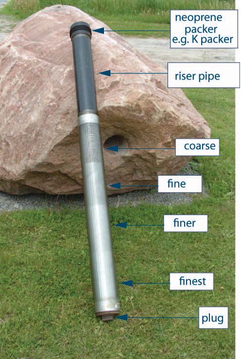
Figure 6-15 shows a sample telescopic screen with multiple slot sizes (from coarse to finest). A typical well screen for use in well construction does not have multiple slot sizes on a small length of screen.
Figure 6-16: An Example of a Telescopic Well Screen Assembly
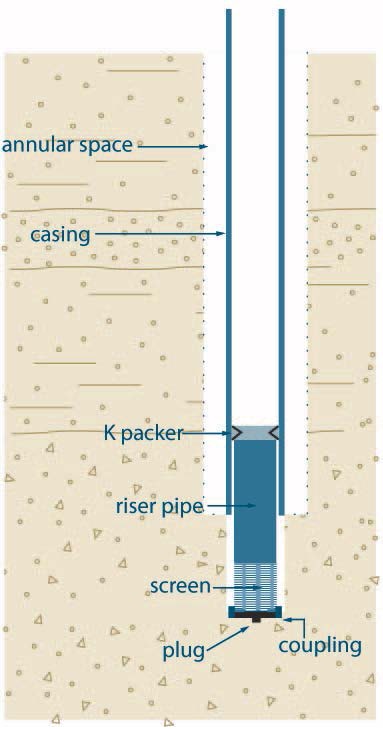
Figure 6-16 shows a cross-sectional diagram of a telescopic well screen assembly. The diagram shows a hole extending vertically into the subsurface. A casing extends from above the ground surface into the hole. An annular space is located between the outside of the casing to the side of the hole. A well screen is shown within the bottom of the casing and extends out of the bottom of the casing into the bottom of the hole in the subsurface. The well screen is made up of a K packer, riser pipe, screen, coupling and plug. The K-packer is located at the top of the well screen and seals the inner casing and to the outside of the well screen. The riser pipe extends from the K-packer to below the bottom of the casing in the subsurface. The screen is located below the riser pipe in the subsurface. The coupling and plug are located below the screen.
Reminder - The diagram above is not to scale, is for illustrative purposes for this chapter only and does not necessarily represent full compliance with other requirements found in the Wells Regulation.
Filter Packs Around Wells Screens for Test Holes or Dewatering Wells
Filter packs are well-sorted gravels or coarse sands that can be:
- developed around the well screen (naturally developed from native granular material),
- selected and placed into the hole surrounding the well screen and developed (artificial filter pack), or
- pre-packed between two manufactured well screens (called pre-packed well screens) and developed.
This packed zone separates the well screen from the natural aquifer material to prevent finer materials from entering the test hole or dewatering well and increases the effective well diameter. Where possible, the filter pack for dewatering wells should extend a sufficient distance above the top of the well screen to allow for settling during development.
Reminder - Unless exempt, the person constructing a new test hole or dewatering well must place filter pack in the annular space around the well screen and casing to the requirements found in the “Plainly Stated” section, Table 7-1A and Table 7-1B of Chapter 7: Annular Space & Sealing.
Best Management Practice – Using Primary and Secondary Filter Packs
For monitoring wells, where possible, primary and secondary filter packs should be used.
The primary filter pack should extend about 0.6 metres (2′) above the top of the slots in the well screen. The secondary filter pack should extend about 0.3 to 0.6 metres (1′ to 2′) above the top of the primary filter pack. The secondary filter pack is typically made of a finer grain material than the primary filter pack. The purpose of the secondary filter pack is to protect the primary filter pack from formation material and sealant.
Primary filter packs should have grains fine enough to retain the formation, but be coarse enough to allow unrestricted flow of groundwater into the well.
Filter packs should contain washed and screened silica sands or gravels or other inert granular material.
When selecting a well screen, a slot size should be chosen that will retain approximately 90% of the natural filter pack material after development (see the “Well Screen Slots, Lengths and Diameter,” section on page 88 of this chapter). The use of a filter pack will generally allow for a coarser well screen slot size. Coarser slot sizes can increase the well efficiency.
Artificial Filter Packs
There are circumstances where an artificial filter pack is preferred over a naturally developed filter pack. Two examples follow:
- Well screens with small screen slots are used with formations having uniform fine grained material. Small slot sizes can create low well efficiency and could reduce the chance of obtaining the desired yield.
- Open hole wells in semi-consolidated bedrock formations can have significant quantities of granular material released off the hole wall. The granular material can enter the water distribution system damaging the pumping equipment and impairing the water quality.
Persons constructing test holes or dewatering wells can remove formation material around a well screen and replace it with a relatively thin zone of coarse material to increase the well’s efficiency, increase hydraulic diameter and prevent granular material from entering the well. The coarse material that is placed around the well screen is called an artificial filter pack.
As an alternative to placing coarse material around the well screen, the person constructing the test hole or dewatering well can install a manufactured pre-packed well screen.
The Wells Regulation requires artificial filter pack material or material in a pre-packed well screen to be clean, washed gravel or sand. The gravel or sand must be placed during or after placement of the well screen and casing.
The following best management practices (including Table 6-11) provides artificial filter pack characteristics for obtaining optimum well yield, and information on placing artificial filter packs.
Best Management Practice – Comparing Filter Packs to Screen Slot Size
The filter pack material type, grain shape, grain size distribution properties and grain size should be compared in order to select the well screen slot size. For further information on filter pack selection see ASTM D 5092-04e1 – “Standard Practice for Design and Installation of Ground Water Monitoring Wells
Further guidance on well screen and filter pack design for dewatering wells can be found in Construction Dewatering and Groundwater Control
Best Management Practice – Optimum Artificial Filter Pack Characteristics
| Characteristics | Advantages |
|---|---|
| Clean and washed (See “clean” in Chapter 2: Definitions & Clarification; Table 2-3) |
|
| Well rounded and uniform grains |
|
| 90 to 95 per cent quartz grains |
|
| Uniformity coefficient of 2.5 or less |
|
| Filter pack thickness should be no more than 20 cm (8″) |
|
| Well screen slot size should retain 90% of filter pack grains |
|
Best Management Practice – Placing Artificial Filter Pack Material
To place an artificial filter pack around a well screen, the hole needs to be properly sized to allow for the well screen and a sufficiently sized annular space around and above the entire well screen. The casing and well screen need to be properly centred in the hole to ensure the person constructing the well places a consistent thickness of filter pack material around the test hole or dewatering well.
To avoid bridging problems, it is important to place artificial filter pack materials in drilled test holes or dewatering wells:
- using a tremie pipe,
- with a reverse circulation of fluids, or
- with a direct circulation of fluids.
If a tremie pipe is used, the tremie pipe should be raised slowly as the filter material builds up around the well screen. The distance to the top of the filter pack should be carefully monitored using the tremie pipe or a weighted line inserted through the tremie to feel the top of the filter pack.
If a test hole or dewatering well casing is being raised to expose a well screen and filter pack to the formation, (see “Pull-Back Method” on page 103), the person constructing the well should consider the following to prevent finer material from entering the well screen:
- When using a tremie pipe, the artificial filter pack material should be placed in stages as the casing is pulled back to expose the filter pack and well screen to the formation.
- A sufficient depth of filter pack material should be maintained above the well screen slots as the casing is withdrawn.
- The filter pack level should never drop below the bottom of the outer casing.
For more information on filter pack design, see Chapter 9 (pages 409 to 419) and Chapter 10 (pages 486 to 491) of Groundwater & Wells, Third Edition
Well Screen Design Considerations for Large Diameter Test Holes or Dewatering Wells
Typically, coarse sand or gravel is installed below concrete tiles or other types of casing material to prevent sediment from entering the well water in excavated (dug) and some bored wells. This area of the well is typically called a stone bed and has the following characteristics:
- It is usually about 30 cm (12″) to 60 cm (24″) thick depending on the environment and well design, and
- It has to be clean, washed and free of contamination.
The following sections provide best management practices for the design of well screens for large diameter wells.
Well Screen Using Large Diameter Fibreglass or Galvanized Material
Best Management Practice – Designing a Well Screen Using Fibreglass or Galvanized Casing in Large Diameter Dug and Bored Wells
In most cases groundwater will enter a large diameter well through the open bottom below the well casing. As a result, slotting of the well casing to create a well screen should not be done.
If it is necessary to obtain groundwater through the sides of the well, then it is important for the person constructing the well to contact the manufacturer of the fibreglass or galvanized casing before creating a well screen by perforating or slotting the casing. Persons constructing wells with these materials should have the manufacturer determine and confirm if the type of slotting or perforating will potentially weaken or collapse the casing (and void the warranty) or cause impairment of the well water.
Reminder - It is important to follow the manufacturer’s specifications when backfilling with clean or washed sand and gravel around the outside of fibreglass and galvanized well screens to prevent collapse and warping in particular environments.
Well Screens Using Large Diameter Concrete Tiles
Where the person constructing the well uses concrete tiles as well casing and well screen in bored or dug wells, the well screen begins at the first unsealed joint in the concrete tiles and ends either at the bottom of the unsealed concrete tiles or any gravel or sand installed below the tiles in the excavated hole.
Best Management Practice – Groundwater Entering Large Diameter Wells Cased with Concrete Tiles
Concrete tiles should be:
- designed to ASTM C478 – 13 – “Standard Specification for Precast Reinforced Concrete Manhole Sections
footnote 47 .” - designed in a manner sufficient to prevent well collapse, and
- carefully and evenly backfilled on the outside to ensure the tiles remain plumb.
Groundwater should only enter a large diameter well through the open bottom below the deepest concreter tile. Where groundwater is to enter through the open bottom of the concrete tiles, all concrete tile joints should be designed to ASTM C990–09 titled Standard Specification for Joints for Concrete Pipe, Manholes, and Precast Box Sections Using Preformed Flexible Joint Sealants.
Reminder - Unless exempt, the person constructing the new well must fill the annular space around the well screen and casing to the requirements found in the “Plainly Stated” section, Table 7-1A and Table 7-1B of Chapter 7: Annular Space & Sealing.
Installing Well Screens in Test Holes and Dewatering Wells
Properly sized and installed well screens and filter packs reduce the risk of formation collapse and sediment in well water. Failure to install or properly install well screens has been the cause of many problems associated with wells in Ontario such as well plugging, pump and waterline damage and sediment or granular material in the water supply.
The method of well screen installation is chosen based on practicality and economic feasibility. A particular test hole or dewatering well design may limit how a well screen can be installed due to:
- aquifer properties,
- methods used to construct the well,
- size and dimensions of the hole, and
- hydraulic conditions.
Some methods of well screen installation include the pull-back, open-hole, single string, jetting and bail-down. This section provides general information on all of these methods. The applications, advantages, and disadvantages are summarized in Table 6-12. Outlines of the steps involved in each of these methods are shown following the table.
Reminder - The methods presented below are for the installation of one well screen in a test hole or dewatering well. For information on the installation of multiple screens in multi-level monitoring wells see Chapter 8: Multi-Level Monitoring Test Holes.
| Methods | Well Construction Equipment | Advantages | Disadvantages |
|---|---|---|---|
| Pull-back | Best suited for drilling systems that advance the casing as the hole is being constructed. For example:
|
Can minimize problems caused by:
Makes it possible to remove and replace the screen without disturbing the casing and sealant (grout) placed around the casing. Allows for the installation of a telescopic well screen without having to use a temporary casing. |
Heaving formation conditions will create installation problems when using a cable tool or air rotary rig. The person constructing the test hole or dewatering well may have to employ one of the following options to set the well screen:
Where there is significant side-wall friction, this method requires a great deal of force to pull back the casing. |
| Open-hole (double string) | Used in:
|
Can minimize problems caused from:
Makes it possible to remove and replace the screen without disturbing the casing and sealant (grout) placed around the casing. Allows for the installation of a telescopic well screen without having to use a temporary casing. |
Need to use drilling fluid to prevent formation collapse below the test hole or dewatering well casing. Using drilling fluid may make well development more challenging. |
| Open-hole (single string) | Used in:
|
Minimizes the risk of complications due to heaving formations when using mud rotary. Well screen (pipe size) can be installed as part of the casing assembly. |
The string offers little column strength and requires support using drilling tools to prevent well screen collapse and crooked test holes or dewatering wells. For deeper wells in formations that are prone to collapse, an extra outer diameter casing may have to be installed and grouted for a significant portion of the test hole or dewatering well. Well screen cannot be removed independently of the casing. |
| Jetting | Commonly used for dewatering wells. |
Less expensive than other methods. |
Only useful for shallow wells obtaining water from sand formations. |
| Driving | Used in:
|
Less expensive than other methods. |
Only useful for shallow wells obtaining water from sand formations. |
| Bail-down |
Used in cable tool rigs and occasionally in rotary drilling rigs in unconsolidated material.
|
Better than the pull-back where significant side-wall friction exists. |
Requires special end fittings for the well screen. |
Pull-Back Method of Well Screen Installation
The general steps involved in the pull-back method (see Figure 6-17) are as follows:
- The casing is installed to the full depth of the test hole or dewatering well. As an alternative, a temporary casing can be installed to the full depth of the test hole or dewatering well. After the casing is placed in the open hole, any cuttings that settle inside should be carefully cleaned out.
Reminder - Installing the casing to the bottom of the test hole or dewatering well is particularly important if a delay is anticipated between drilling and well screen installation. The casing will prevent a partial or full collapse of the formation into the hole.
- Where a temporary casing has been installed, a permanent smaller diameter well casing is lowered into the temporary casing to the bottom of the hole. A telescopic well screen is pushed inside the permanent casing to the bottom. The bottom of annular space between the temporary and permanent casings is filled with a filter pack material to a height that extends above the well screen.
Reminder - A weight should be placed on the bottom of the well screen to stop the well screen from migrating upward while the casing is being pulled back prior to proceeding to Step 3. The weight also creates tension to help the person constructing the test hole or dewatering well determine the exact position of the well screen during the pull-back procedure.
-
- Where a temporary casing has been installed, the permanent casing is pulled back exposing the well screen and filter pack. Then the temporary well casing is carefully pulled back to expose the well screen and filter pack to the formation.
- In cases where a temporary well casing has not been installed, the casing is pulled back (or lifted) far enough to expose the well screen to the water-bearing formation. The bottom of the casing is raised so that the packer at the top of the well screen remains connected and sealed to the casing, and to maximize the screen exposure.
Some methods of lifting the casing include the following:
- jarring and then lifting the casing with the drilling tools, a bumping block or drive clamp,
- lifting the casing using mechanical or hydraulic jacks, and
- using a pulling ring or spider with wedges or slips to grip and lift the casing. Adding clean water to the well during this process may also help.
- In situations where no temporary casing has been installed, the well screen will need to be held in place until it is set in the formation. It is important that care be taken to prevent the movement of the well screen during the well development and the placement of suitable sealant in the annular space. See the Tips for Installing Telescopic Well Screens in the next section for further information on preventing the movement of the well screen.
Reminder - In situations where the new test hole or dewatering well will be in operation for more than 180 days and where a temporary casing has been installed and lifted to expose the well screen and filter pack, the temporary casing must be fully removed from the well to meet the requirements for placement of suitable sealant in the annular space (See Chapter 7: Annular Space & Sealing).
Tips for Installing Telescopic Well Screens
Tips for the installation of a telescopic screen are as follows:
- To ensure extra safety when installing the well screen and maximum exposure of the well screen to the aquifer, a riser pipe (see Figure 6-17) with K-packers should be attached to the top of the well screen. The riser pipe and K-packers will seal the top of the well screen to the bottom of the casing and prevent the well screen from slipping out of the bottom of the well casing. This will also prevent formation material from entering the test hole or dewatering well between the well screen and casing.
- When developing the test hole or dewatering well by surging water into and out of the well screen in loose sand formations, the well screen can easily slip out the bottom of the casing. A riser pipe with multiple K-packers is especially helpful to hold the well screen in place during development of the test hole or dewatering well.
- To ensure the well screen is placed in the correct location below the well casing, the depths from the ground surface should be accurately and carefully measured.
Figure 6-17: Drilled Well in Overburden-Casing Pull-Back Method to Expose Well Screen
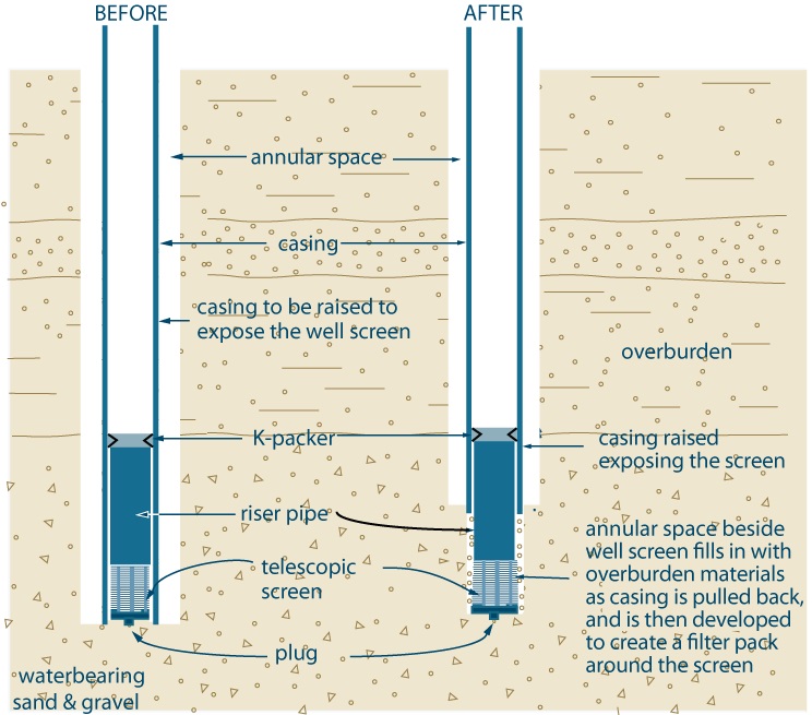
Figure 6-17 shows a cross-sectional diagram of a drilled well in overburden where a casing has been pulled back to expose a well screen. Figure 6-17 shows two steps.
The first step (Before) is shown on the left side of the diagram. The diagram shows a hole is extending vertically into a water-bearing sand and gravel deposit in the subsurface. A casing extends from above the ground surface to the bottom of the hole. An annular space is located between the outside of the casing to the side of the hole. A well screen is shown within the bottom of the casing. The well screen is made up of a K packer, riser pipe, telescopic screen, coupling and plug. The K-packer is located at the top of the well screen and seals the inner casing and well screen. The riser pipe extends downward from the K-packer to a screen. The screen is located below the riser pipe. The coupling and plug are located below the screen.
The second step (After) is shown on the right side of the diagram. The diagram shows a hole extending vertically into the subsurface. A casing extends from above the ground surface into the subsurface. An annular space is located beside the outside of the casing to the side of the hole. A well screen is shown within the bottom of the casing and extends out of the bottom of the casing into the subsurface. The well screen is made up of a K packer, riser pipe, telescopic screen, coupling and plug. The K-packer is located at the top of the well screen and seals the inner casing and well screen. The riser pipe extends from the K-packer to below the bottom of the casing in the subsurface. The screen is located below the riser pipe in the subsurface. The coupling and plug are located below the screen.
There is text associated with the second step that states “casing raised exposing the screen” and “annular space beside well screen fills in with overburden materials as casing is pulled back, and is then developed to create a filter pack around the screen”.
Reminder - This figure is not to scale, is for illustrative purposes for this chapter only, and does not necessarily represent full compliance with the requirements found in the Wells Regulation.
Open-Hole/Double String Method of Well Screen Installtionfootnote 48
This method generally consists of drilling below the casing while maintaining drilling fluid in the well to hold the well open below the casing. A telescopic well screen is installed into the open space below the well casing.
The general steps for the open-hole/double string method (see Figure 6-18) are as follows:
- The casing is installed into the well and the annular space is filled with suitable sealant (see Chapter 7: Annular Space & Sealing). The bottom of the casing is slightly below where the top of well screen will be placed.
- The casing is filled with drilling fluid (e.g., mud). The well is drilled through the bottom of the well casing to make room for the well screen. In some cases, where the formation can be held open (e.g., bedrock, till), drilling fluid is not necessary.
- A telescopic well screen is lowered or pushed inside the casing to the bottom of the well. Then the “Tips for Installing Telescopic Well Screens” section on page 104 of this chapter should be followed.
- If used to hold the hole open, the drilling fluid is removed.
- The well should then be developed.
Figure 6-18: Example of an Open Hole, Double String Method of Screen Installation
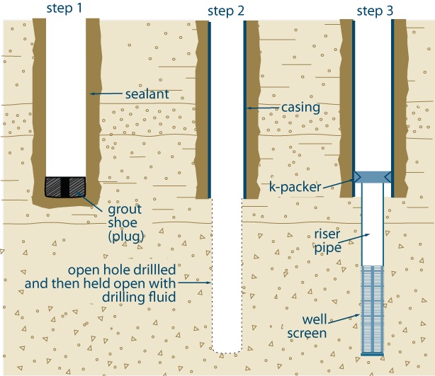
Figure 6-18 shows a cross-sectional diagram of a drilled well in overburden where an open hole, double string method is used to install a well screen. Figure 6-18 shows three steps
.
The first step (Step 1) is on the left side of the diagram. The diagram shows a hole extending vertically into the subsurface. In the hole, a casing extends from the ground surface to just above the bottom of the hole. An annular space is located beside the outside of the casing to the side of the hole. A grout shoe is located at the bottom of the casing. Sealant has been placed in the annular space between the outside of the casing and the side of the hole and also in the bottom of the hole below the bottom of the casing and the grout shoe.
The second step (Step 2) is in the centre of the diagram. The diagram shows a hole extending vertically into the subsurface. In the hole, a casing extends from the ground surface to about half of the distance from above the bottom of the hole. An annular space is shown beside the outside of the casing to the side of the hole. Sealant has been placed in the annular space between the outside of the casing and the side of the hole. The remainder of the hole below the bottom of the casing is held open with a drilling fluid.
The third step (Step 3) is on the right side of the diagram. The diagram shows a hole extending vertically into the subsurface. A casing extends from above the ground surface into the hole below the subsurface. An annular space is located beside the outside of the casing to the side of the hole. A well screen is located within the bottom of the casing and extends out of the bottom of the casing to the bottom of the hole in the subsurface. The well screen is made up of a K packer, riser pipe and well screen. The K-packer is located at the top of the well screen and seals the inner casing and well screen. The riser pipe extends from the K-packer to below the bottom of the casing in the subsurface. The screen is located below the riser pipe in the subsurface.
Reminder - This figure is not to scale, is for illustrative purposes for this chapter only, and does not necessarily represent full compliance with the requirements found in the Wells Regulation.
Open Hole/Single String Method of Well Screen Installationfootnote 49
The general steps for the open hole/single string method (see Figure 6-19) are as follows:
- The well screen is attached to the bottom of the first length of casing to be installed in the test hole or dewatering well as one assembly (i.e. one string). If the well screen is smaller (in diameter) than the casing, it can be welded or threaded to the casing with a flared weld ring or cone adapter. If the well screen is the same size as the casing, it can be welded or threaded directly to the bottom of the casing.
- Drilling fluid (e.g. mud) is added into the open hole to prevent any collapse of the sides of the well. As an alternative, an outer temporary casing can be installed to the bottom of the well.
- The string is installed in the hole to almost the bottom of the well. Where a temporary outer casing is installed, the inner casing, well screen and filter pack are installed within the outer casing and steps 4 and 6 do not apply.
- The drilling fluid is thinned to allow the fluid to enter through the slots of the well screen as the string is lowered into the hole. If drilling fluid does not enter into the well screen, the pressure of the drilling fluid could cause the well screen to collapse.
- Because the string is long and slender, it offers little column strength and it requires lateral support to prevent well screen collapse and crooked wells. When this string is installed in an open hole without side support, the string should be suspended from the surface using casing elevators without resting the string on the bottom of the hole.
- Once installed, the well screen and casing can be filled with water to displace the drilling fluid.
- For naturally developed wells, the drilling fluid is removed and the fine grained material in the formation is induced to enter the well screen leaving the coarser material on the outside of the well screen. When artificial filter packs are used, the pack material is placed around the well screen and the lower portion of the well casing. The well development process is similar to the natural development of a well. If a temporary outer casing has been installed, the temporary casing is removed to expose the string and filter pack. The well should then be developed.
- Collapse of the subsurface formation around the string provides lateral support and the full weight of the string can be safely released from the drilling rig.
Reminder - In situations where the test hole or dewatering well will be in operation for more than 180 days and where a temporary casing has been installed and lifted to expose the well screen and filter pack, the temporary casing must be fully removed from the well to meet the requirements for placement of suitable sealant in the annular space (See Chapter 7: Annular Space & Sealing).
Tips for Installing Strings
Tips for string installation are as follows:
- Centralizers can help maintain alignment of the casing and well screen string. Centralizers are recommended for well screens that are greater than 6 m (19.7′) in length.
- If a clay or silt deposit is located beneath the well screen, it is important to prevent the clay or silt from heaving up next to the well screen during well development. Two methodologies to prevent clay or silt from entering the well screen are as follows:
- When placed around the well screen, an artificial filter pack can act as a formation stabilizer to hold the clay or silt deposit in place during development (see the section titled “Artificial Filter Packs” on page 96 of this chapter). The grain size of the filter pack should be chosen as described in Table 6-11.
- For wells with a large annular space around the well screen, a shale trap or formation packer can be mounted on the bottom of the casing above the well screen. Using this methodology, the formation will collapse around the well screen and below the shale trap or packer. The shale trap or packer will hold the formation in place to prevent heaving of the underlying clay or silt deposit towards the well screen during development
footnote 50 .
- For deeper wells in formations that are prone to collapse, a larger diameter outer casing should be installed and grouted for a significant portion of the well. The lower portion of the well should be drilled through the bottom of the outer casing to the desired depth. It is important that the well casing and open portion of the well be filled with drilling fluid. A smaller diameter casing and well screen string is then installed in the well using the same process as described in the general steps.
- To eliminate the need to run two strings of casing to place the artificial filter pack material, a pre-packed screen should be used.
Figure 6-19: Single String Method Using Outer Casing
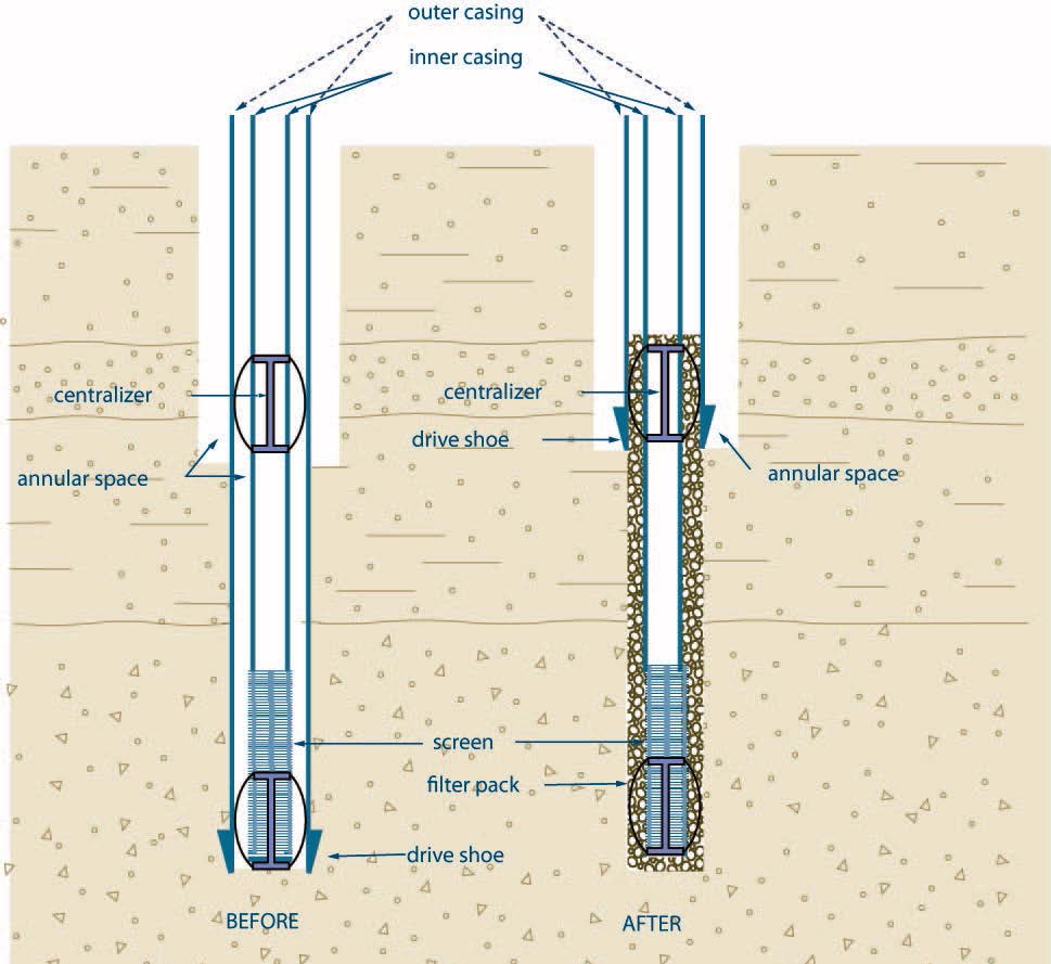
Figure 6-19 shows a cross-sectional diagram of a drilled well in overburden where an open hole, single string method is used to install a well screen. Figure 6-19 shows two steps.
The first step (Before) is on the left side of the diagram. The diagram shows a hole extending vertically into the subsurface. An outer casing with a drive shoe extends from above the ground surface to the bottom of the hole. The drive shoe is located on the bottom of the outer casing. An annular space is located beside the outside of the outer casing to the side of the hole. The annular space extends from the ground surface to above halfway from the bottom of the hole. An inner casing with a well screen extends above the ground surface to the bottom of the hole within the outer casing. The well screen is attached to the bottom of the inner casing at the bottom of the hole. There is an annular space between the inner casing and outer casing and between the well screen and the outer casing. A centralizer has been placed at the bottom of the hole between the well screen and outer casing. A second centralizer has been placed in the middle of the hole between the inner casing and the outer casing.
The second step (After) is on the right side of the diagram. The diagram shows a hole extending vertically into the subsurface. An outer casing with a drive shoe extends from above the ground surface to about half the depth of the hole. The drive shoe is located on the bottom of the outer casing. An annular space is located beside the outside of the outer casing to the side of the hole. The annular space extends from the ground surface to above halfway from the bottom of the hole. An inner casing with a well screen extends above the ground surface to the bottom of the hole within the outer casing. The well screen is attached to the bottom of the inner casing at the bottom of the hole. There is an annular space between the inner casing with well screen and the outer casing. There is also an annular space between the inner casing with well screen and the side of the hole below the outer casing. A centralizer has been placed at the bottom of the hole between the well screen and outer casing. A second centralizer has been placed in the middle of the hole between the inner casing and the outer casing. Filter pack has been placed in the annular space around the outside of the inner casing with well screen from the bottom of the well screen to the top of the middle centralizer.
Reminder - This figure is not to scale, is for illustrative purposes for this chapter only, and does not necessarily represent full compliance with the requirements found in the Wells Regulation.
Bail-Down Method of Well Screen Installationfootnote 51
The objective of the bail-down method is to remove sediment from below the well screen. The removal of sediment should allow the well screen to settle into position below the bottom of the casing.
The general steps for the bail-down method (see Figure 6-20) are as follows:
- The casing is installed into a test hole or dewatering well. The annular space is filled with suitable sealant (see Chapter 7: Annular Space & Sealing). The bottom of the casing is located slightly below where the top of the well screen will be placed.
- The bail-down shoe, heavy nipple and float shoe are assembled in the bottom of a telescopic well screen. The well screen will need a threaded bailing pipe (similar to a riser pipe) with K-packers.
- The assembly is lifted from the bailing pipe and lowered into the well. Additional lengths of bailing pipe are added to the assembly as it is lowered into the well until the well screen reaches the bottom of the well.
- A bailer (e.g., a sand pump) is placed inside the bailing pipe. Then the formation material is bailed below the shoe fitting on the well screen. As the formation material is removed, the weight of the well screen and bail pipe causes the well screen to move downward below the bottom of the casing. It is important to carefully measure where the well screen is to be located below the well casing.
- A weighted and tapered plug is dropped through the bailing pipe to plug the heavy nipple on the bail-down shoe. When the plug is in place, the bail pipe is unthreaded from the well screen and removed from the well. The well should then be developed.
- In other cases, the well screen is not connected to the bailing pipe. Instead, the bailing pipe is fitted with a flange or coupling large enough to press on the neoprene packer at the top of the well screen to hold it in place. To prevent the well screen from sinking below the casing, care needs to be taken as the movement of the well screen cannot be controlled during the bailing process.
Figure 6-20: Bail-Down Method of Screen Installation
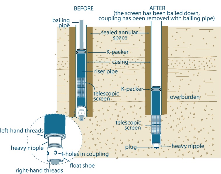
Figure 6-20 shows a cross-sectional diagram of a drilled well in overburden where a bail down method has been used to install a well screen. Figure 6-20 shows two steps.
The first step (Before) is on the left side of the diagram. The diagram shows a hole extending vertically into the subsurface. In the hole, a casing extends from above the ground surface to just above the bottom of the hole. A sealed annular space is located beside the outside of the casing to the side of the hole. A bailing pipe, leading pipe with k-packer, telescopic screen and a bail-down shoe, heavy nipple and float shoe have been placed within the casing. The bailing pipe extends from above the ground surface to the leading packer and k-packer. The k-packer seals the top of the leading pipe to the inner casing. The telescopic well screen is affixed to the bottom of the leading pipe. The bail-down shoe, heavy nipple and float shoe are affixed to the bottom of the screen. The bail-down shoe, heavy nipple and float shoe extend to the bottom of the hole inside the casing.
An exploded view of the bail-down shoe, heavy nipple and float shoe is shown below and to the left of the first step (Before) diagram. The exploded view shows a cross-sectional diagram of a left handed thread joining the bottom of the well screen to the heavy nipple of the bail-down shoe. A float shoe with holes in its coupling is affixed to the heavy nipple. The bottom of the float shoe has right hand threads.
The second step (After) is on the right side of the diagram. The second step represents the screen bailed down and the coupling and bailing pipe have been removed from the well. The diagram shows a hole extending vertically into the subsurface. In the hole, a casing extends from above the ground surface to the same location as the first step (Before). A sealed annular space is located beside the outside of the casing to the side of the hole. A leading pipe with k-packer, telescopic screen and a bail-down shoe, heavy nipple and float shoe have been placed within the casing. A small distance above the bottom of the casing, the k-packer seals the top of the leading pipe to the inner casing. Below the bottom of the casing, the telescopic well screen is affixed to the bottom of the leading pipe. The bail-down shoe, heavy nipple and plug are affixed to the bottom of the screen. The bail-down shoe, heavy nipple and plug extend to the bottom of the hole.
Reminder - This figure is not to scale, is for illustrative purposes for this chapter only, and does not necessarily represent full compliance with the requirements found in the Wells Regulation.
Jetting Methods for Well Screen Installationfootnote 52
Jetting methods are typically used to install well screens to depths of no more than 7.5 m (25′) below the ground surface in sand formations. There are three jetting methods used to install a well screen:
- Jetting adjacent to the casing and well screen (see Figure 6-21),
- Jetting using a wash pipe (see Figure 6-22), and
- Jetting and driving using a drop line and chisel-point bit (Figure 6-23).
Jetting Adjacent to the Casing and Well Screen
The general steps for this method (see Figure 6-21) are as follows:
- An external pipe is placed adjacent to the casing and well screen string.
- Water is jetted down through the pipe displacing the formation material.
- The jetting action allows the string to sink into the sand formation to the required depth.
- After the jetting pipe has been removed, the test hole or dewatering well should then be developed.
Reminder - See Chapter 7: Annular Space & Sealing for information on the filling of the annular space for a jetted well.
Figure 6-21: Jetting Adjacent to the Casing and Well Screen
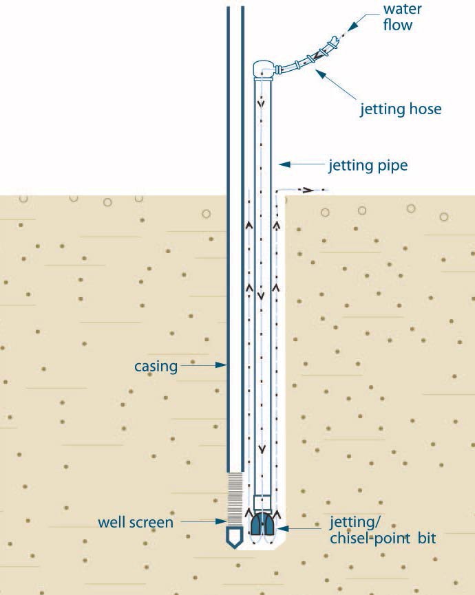
Figure 6-21 shows a cross-sectional diagram of jetting a well screen and casing into the subsurface. The diagram shows a hole extending vertically into the subsurface. A casing extends from above the ground surface into the hole. A well screen is attached to the bottom of the casing. A driven-point is attached to the bottom of the screen. The driven-point extends to the bottom of the hole. The casing, screen and driven-point are located on the left side of the hole.
A jetting pipe with a jetting/chisel-point bit extends from above the ground surface to the bottom of the hole. The equipment is located on the right side of the hole and to the right of the casing and well screen. The jetting/chisel-point bit is attached to the bottom of the jetting pipe. A jetting hose is attached to the top of the jetting pipe.
There are arrows in the diagram demonstrating the flow of water through the jetting hose down the jetting pipe and discharging out of the jetting/chisel-point bit. There are more arrows in the diagram showing the flow of water and subsurface materials flowing up and around the jetting pipe and discharging out of the hole onto the ground surface.
Reminder - This figure is not to scale, is for illustrative purposes for this chapter only, and does not necessarily represent full compliance with the requirements found in the Wells Regulation.
Jetting Using a Wash Pipe
The general steps for this method (see Figure 6-22) are as follows:
- A temporary wash pipe is assembled inside the well screen prior to attachment of the well screen to the bottom of the casing. The bottom of the wash pipe ends near the bottom of the well screen. The wash pipe passes up through the well screen and usually continues upward to about 30 – 60 cm (12 – 24″) into the casing (see Figure 6-22). The wash pipe may extend to the surface in some shallow wells.
- A coupling is screwed to the lower end of the wash pipe. The coupling rests in a conical seat in the self-closing wash-down fitting, which is equipped with a plastic ball closure.
- A semi-rigid, plastic ring seal is slipped over the upper end of the wash pipe and is pushed into the top of the well screen. The purpose of this upper ring seal is to close the space around the top of the wash pipe and to direct the jetting water down into the wash pipe.
- Water is pumped into the casing, through the wash pipe and jets down through the bottom of the self-closing wash-down fitting.
- In sand formations, the jetting action allows the string of casing and well screen to sink into the water–bearing formation.
- To achieve depths greater than 7.5 m (25′), it is important to mix drilling fluid additives with the jetting water to suspend cuttings and stabilize the hole in the event that the circulation of the drilling fluid is interrupted.
- During this process, some of the jetting water leaks from around the bottom of the wash pipe and flows out through the well screen openings. This prevents fine sand from passing into the well screen and locking the wash pipe inside the well screen.
- When the well screen has been set at the proper depth, the wash pipe is extracted from the well using a fishing tool.
- After the wash pipe has been removed, then the well should be developed.
Figure 6-22: Jetting Small-Diameter Well Screen into Place By Using a Wash Pipe
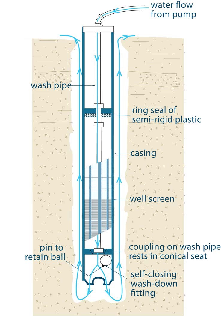
Figure 6-22 shows a cross-sectional diagram of jetting a small diameter well screen into place using a wash pipe.
The diagram shows a hole extending vertically into the subsurface. The diagram shows the wash pipe and other equipment working to create the well. A casing extends from above the ground surface into the hole. A well screen is attached to the bottom of the casing. A wash pipe extends into the top of the casing and into the well screen. At the bottom of the wash pipe, a self-closing, wash-down fitting ball has been attached to allow water to discharge out of the wash pipe but prevent subsurface materials from entering into the well. A pin to retain the self-closing wash-down fitting ball is affixed to the ball. The bottom of the wash pipe has a coupling that rests in a conical seat. Near the upper portion of the casing in the hole, a ring seal has been placed between the wash pipe and the inside of the casing.
There are arrows in the diagram demonstrating the flow of water from a pump through the wash pipe and discharging out of the wash pipe into the hole. There are more arrows in the diagram showing the flow of water and subsurface materials flowing up and around the casing and discharging out of the hole onto the ground surface.
Reminder - This figure is not to scale, is for illustrative purposes for this chapter only, and does not necessarily represent full compliance with the requirements found in the Wells Regulation.
Jetting and Driving Using a Drop Line and Chisel-Point Bit
The general steps for this method (see Figure 6-23) are as follows:
- A chisel point bit is attached to the bottom of a drop line. The drop line is placed within the well casing.
- Water is jetted through the drop line and the jetting pipe is rotated by hand and adjusted vertically. During jetting, material is washed upward between the inside of the casing and the outside of the drop line. The drop line and bit are also intermittently driven during the process. During the process, the casing moves downward to the required depth.
- The drop line is removed and a telescopic well screen point is inserted. Then, the well screen point is driven out the bottom of the casing. As an alternative, the well screen can be inserted into the bottom of the casing. Then the pull-back method can be used to lift the well casing and expose the well screen to the formation.
Figure 6-23: Jetting and Driving Using a Drop Line and Chisel-Point Bit
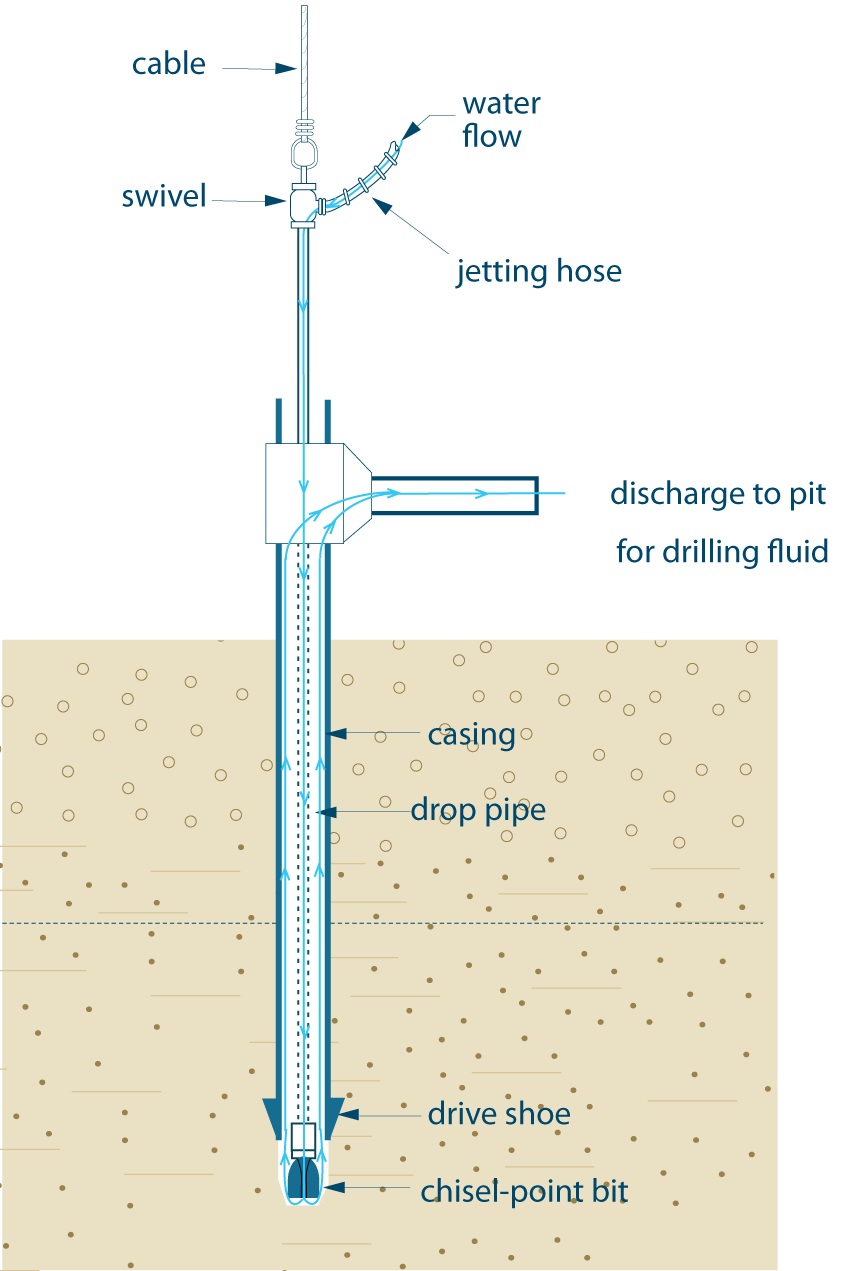
Figure 6-23 shows a cross-sectional diagram of jetting and driving a well screen simultaneously.
The diagram shows the drop pipe, casing and other equipment working to create the well. The diagram shows a hole extending vertically into the subsurface. A casing with a drive shoe extends from above the ground surface into the hole. The drive shoe is attached to the bottom of the casing. A horizontal discharge pipe is attached to the upper portion of the casing above the ground surface.
A jetting pipe extends from above the top of the casing and horizontal discharge pipe into the casing. The bottom of the jetting pipe extends to the bottom of the casing. A chisel-point bit is attached to the bottom of the jetting pipe and is located below the casing.
Above the ground surface, a swivel is attached to the top of the jetting pipe. A jetting hose is attached to the top of the jetting pipe. A vertical cable is shown affixed to the top of the swivel to hold up the jetting hose and jetting pipe above the ground surface.
There are arrows in the diagram demonstrating the flow of water through the jetting hose down the jetting pipe and discharging out of the chisel-point bit. There are more arrows in the diagram demonstrating the flow of water and subsurface materials flowing up and around the jetting pipe within the casing. The arrows in the diagram water demonstrate water and subsurface materials flowing out of the casing into the horizontal discharge pipe and discharging out of the hole onto the ground surface.
Reminder - This figure is not to scale, is for illustrative purposes for this chapter only, and does not necessarily represent full compliance with the requirements found in the Wells Regulation.
Driving Methods of Well Screen Installation
Driving methods are typically used to install well screens to depths of no more than 7.5 m (25′) below the ground surface in sand formations. There are two common driving methods used to install a well screen:
- driving a telescopic well screen below the casing, and
- driving a casing and well screen string.
Driving a Telescopic Well Screen Below the Casing
- A casing is installed within the water-bearing formation.
- A telescopic well screen point is inserted with a drive bar. The well screen is driven to expose it below the bottom of the casing while maintaining the seal with the casing.
Driving a Casing and Well Screen String
- Using a drive bar, the casing and well screen string are driven to the water-bearing formation.
- As an alternative, hollow-stem augers are placed into the ground to the water-bearing formation. The casing and well screen string are placed inside the hollow-stem augers. The well screen and a portion of the casing are driven with a drive bar below the augers. As the augers are backed out of the hole, the annular space between the augers and the string is filled with an artificial filter pack, where necessary, and a suitable sealant.
Tips When Driving Well Screens
The following tips should be considered when driving a well screen:
- Driving methods require additional care in sealing the joint between the driven point well screen and casing and between other casing joints.
- Driving methods require additional care to ensure that the impact of driving does not damage the casing, well screen or joints.
- If a boulder, cobble or other large obstacle is encountered, the casing and well screen string may be damaged or deflected. The string may have to be pulled and the hole properly abandoned (See Chapter 16: Abandonment: When to Plug & Seal Test Holes & Dewatering Wells and Chapter 17: Abandonment: How to Plug & Seal Test Holes & Dewatering Wells). The string will have to be relocated.
- It is important to use commercially manufactured steel driven points to penetrate the formation.
Reminder - For further information see Figure 6-32 in this chapter, Figure 7-9 and the “Grout Placement – Annular Space for Driven Points” section in Chapter 7: Annular Space & Sealing.
Diagrams of Common Types of Wells
Reminder - Figure 6-24 to Figure 6-33 (on pages 119 to 128) show cross-sectional illustrations and relevant graphics for various types of test holes and dewatering wells that have been discussed in this chapter. The illustrations include the minimum size of hole, the length of casing, the type of well screen and annular space filling materials around the well screen.
Reminder - All figures and diagrams are for illustrative purposes only and do not necessarily represent full compliance with other requirements found in the Wells Regulation (e.g. well covering during construction).
Reminder - For details on the requirements involved in sealing the annular space and completing the well, refer to the following chapters in this manual:
- Chapter 7: Annular Space & Sealing
- Chapter 9: Completing the Test Hole or Dewatering Well Structure
Each of the wells shown in Figure 6-24 to Figure 6-33 may encounter conditions that require specialized design or construction. For example:
- flowing artesian conditions,
- presence of gas, and
- sucking and blowing (breathing) conditions where the well and aquifer formation are significantly affected by changes in atmospheric pressure
Reminder - The illustrations and graphics may not depict every circumstance.
Figure 6-24: Examples of Wells Constructed by Drilling or Direct Push Without Using a Driven Point (Not Scheduled to be Abandoned Within 180 Days After Completing Structural Stage)
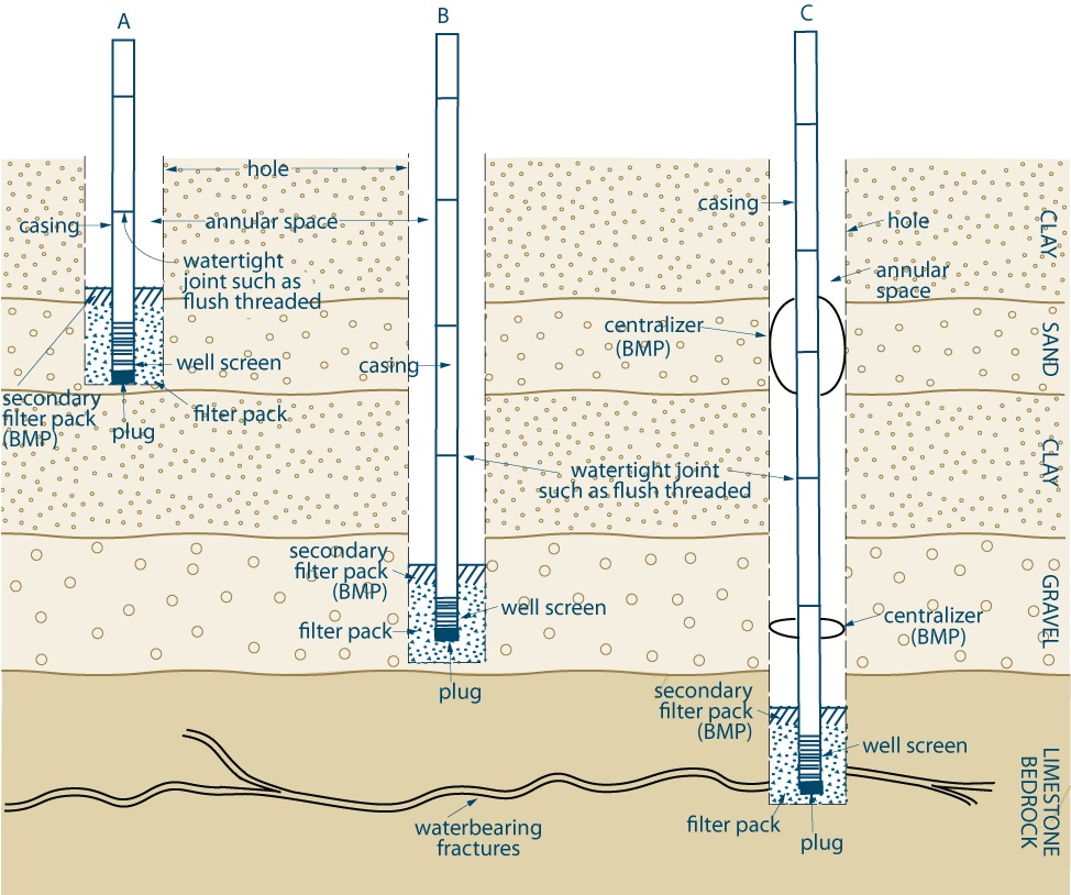
Figure 6-24 shows a cross-sectional diagram of three drilled wells (A, B and C) placed into the subsurface. The subsurface consists of a clay deposit underlain by a sand deposit. The sand deposit is underlain by a clay deposit. The clay deposit is underlain by a gravel deposit. The gravel deposit is underlain by a limestone bedrock with waterbearing fractures.
The well on the left of the diagram is example “A”. The well is completed with a casing that extends vertically from above the ground surface through the clay and into the sand overburden. A well screen is attached to the bottom of the casing. A plug is attached to the bottom of the well screen. A filter pack has been placed around the well screen to the side of the hole. A secondary filter pack has been placed on top of the filer pack. The top of the secondary filter pack extends just above the sand deposit. An annular space exists above the secondary filter pack.
The well in the middle of the diagram is example “B”. The well is completed with a casing that extends vertically from above the ground surface to the gravel deposit. A well screen is attached to the bottom of the casing. A plug is attached to the bottom of the well screen. A filter pack has been placed around the well screen to the side of the hole. A secondary filter pack has been placed on top of the filer pack. The top of the secondary filter pack extends just above the gravel deposit. An annular space exists above the secondary filter pack.
The well on the right side of the diagram is example “C”. The well is completed with a casing that extends vertically from above the ground surface through overburden to the limestone bedrock. As a best management practice (BMP), centralizers have been placed from the outside of the casing to the side of the hole to centre the casing in the hole. A well screen is attached to the bottom of the casing and is located at the water bearing zone in the bedrock. A plug is attached to the bottom of the well screen. A filter pack has been placed around the well screen to the side of the hole. A secondary filter pack has been placed on top of the filer pack. The top of the secondary filter pack is located in the bedrock. An annular space exists above the secondary filter pack.
Note 1 states BMP = Best management practice
Note 2 states the top of the filter pack around the well screen must be no closer than 2.5 metres (8.2 feet) below the ground surface.
Note 3 states the hole diameter must be at least 7.6 centimetres (3 inches) greater than the final outer casing (see A or B) for at least 6 metres (19.7 feet) from the ground surface or the full depth of the well (whichever is less).
Note 4 states the hole must be large enough to allow for the installation of a tremie pipe in the annular space.
Note 5 states if centralizers are used with rotary equipment or a breakaway guide is used with a cable tool equipment, the hole diameter must be at least 5.1 centimetres (2 inches) greater than the final outer casing (see C) for at least 6 metres (19.7 feet) from the ground surface or the full depth of the well (whichever is less).
Note 6 states the diagram applies to all wells other than wells constructed by the use of a driven or jetted point, dug wells and bored wells with concrete casing.
Note 7 states the hole can be held open by using a starter casing or drilling fluids/muds.
Reminder - See “Filter Packs around Well Screens for Test Holes or Dewatering Wells” on page 95 of this chapter for filter pack material information and best management practices about filter packs.
Reminder - This figure is not to scale, is for illustrative purposes for this chapter only, and does not necessarily represent full compliance with the requirements found in the Wells Regulation.
Figure 6-25: Example Multi-Cased Bedrock Well Constructed by Drilling or Direct Push Without Using a Driven Point (Not Scheduled to be Abandoned Within 180 Days After Completing Structural Stage)
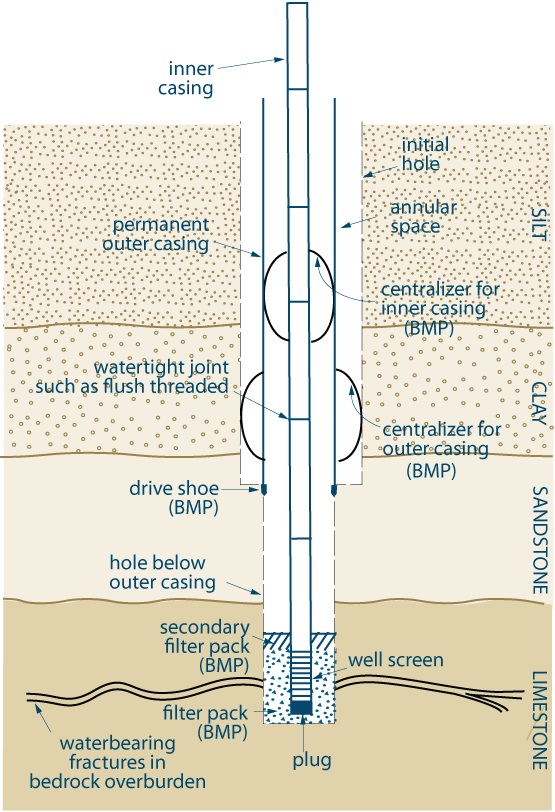
Figure 6-25 shows a cross-sectional diagram of multi-cased bedrock well placed into the subsurface. The subsurface consists of a silt deposit underlain by a clay deposit. The clay deposit is underlain by sandstone bedrock. The sandstone is underlain by a limestone bedrock with water bearing fractures.
The well is completed with an inner casing that extends vertically from above the ground surface through overburden to the limestone bedrock. The joints between the sections of inner casing have been made watertight. An outer casing has been placed in the well that extends vertically from above the ground surface through overburden to the sandstone bedrock. A drive shoe has been placed on the outer casing. As a best management practice (BMP), centralizers have been placed from the outside of the outer casing to the side of the hole to centre the outer casing in the hole. As a best management practice (BMP), centralizers have been placed from the outside of the inner casing to the side of the outer casing to centre the inner casing in the hole. A well screen is attached to the bottom of the inner casing and is located at the water bearing zone in the bedrock. A plug is attached to the bottom of the well screen. A filter pack has been placed around the well screen to the side of the hole. A secondary filter pack has been placed on top of the filer pack. The top of the secondary filter pack is located in the bedrock. An annular space exists above the secondary filter pack.
Note 1 states BMP = Best management practice
Note 2 states as a necessary modification, the hole diameter must be at least 7.6 centimetres (3 inches) greater than the permanent outer casing from the ground surface to at least the bottom of the permanent outer casing or 6 metres (19.7 feet), whichever is less. As a best practice, the permanent outer casing should extend from the ground surface to as close to the top of the well screen as possible.
Note 3 states if centralizers are used with rotary equipment or a breakaway guide is used with a cable tool equipment, the hole diameter must be at least 5.1 centimetres (2 inches) greater than the final outer casing.
Note 4 states the hole can be held open using starter (temporary) casing or drilling fluids (mud).
Note 5 states in this example, the permanent outer casing should be seated and sealed into the bedrock.
Note 6 states the annular space around the permanent outer casing must be filled with suitable sealant as described in Chapter 7: Annular Space & Sealing. The annular space between the casings must be sealed as described in Chapter 7. As a best management practice, the annular space below the permanent outer casing should be filled as described in the best management practice in this chapter, Chapter 7 and, if applicable, Chapter 8.
Reminder - See “Filter Packs around Well Screens for Test Holes or Dewatering Wells” on page 95 of this chapter for filter pack material information and best management practices about filter packs.
Reminder - This figure is not to scale, is for illustrative purposes for this chapter only, and does not necessarily represent full compliance with the requirements found in the Wells Regulation.
Figure 6-26: Examples of Directional Well Constructed by Drilling or Direct Push Without Using a Driven Point (Not Scheduled to be Abandoned Within 180 Days After Completing Structural Stage)
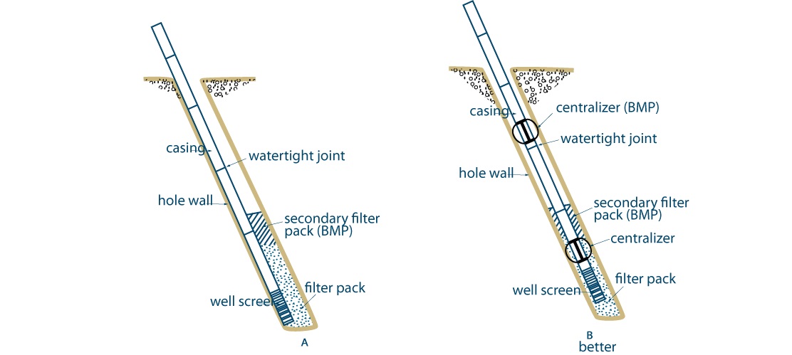
Figure 6-26 shows a cross-sectional diagram of two drilled wells (A and b) placed into the subsurface.
The well on the left of the diagram is example “A”. The well is completed with a casing that extends at a 45 degree angle downward from left to right into the subsurface. The joints between the sections of inner casing have been made watertight. A well screen is attached to the bottom of the casing. The casing and well screen are adjacent to the left side of the hole. A filter pack has been placed around the well screen to the side of the hole. A secondary filter pack has been placed on top of the filer pack. The top of the secondary filter pack extends just above the sand deposit. An annular space exists above the secondary filter pack where the casing and well screen are not against the side of the hole.
The well in the right of the diagram is example “B”. The well is completed with a casing that extends at a 45 degree angle downward from left to right into the subsurface. The sections of the casing have been attached to one another with watertight joints. A well screen is attached to the bottom of the casing. Centralizers have been placed on the casing to centre the casing and well screen in the hole. A filter pack has been placed around the well screen to the side of the hole. A secondary filter pack has been placed on top of the filer pack. The top of the secondary filter pack extends just above the sand deposit. An annular space exists above the secondary filter pack.
Note 1 states BMP = Best management practice
Note 2 states it is important to use centralizers to centre the casing into the hole (see B). A centred casing allows for the proper distribution of filter pack around the well screen and sealant around the casing. The absence of centralizers forces the casing and well screen to move to one side of the hole (see A). This prevents the installation of filter pack around the well screen and the even placement of sealant around the casing. This can allow formation materials to plug the well screen and increases the risk of contaminant and foreign material migration along the side of the casing.
Note 3 states the hole diameter must be at least 7.6 centimetres (3 inches) greater than the final outer casing (see A or B) for at least 6 metres (19.7 feet) from the ground surface or the full depth of the well (whichever is less).
Note 4 states the top of the filter pack around the well screen must be no closer than 2.5 metres (8.2 feet) below the ground surface.
Note 5 states if centralizers are used with rotary equipment or a breakaway guide is used with a cable tool equipment, the hole diameter must be at least 5.1 centimetres (2 inches) greater than the final outer casing (see C) for at least 6 metres (19.7 feet) from the ground surface or the full depth of the well (whichever is less).
Note 6 states the hole must be large enough to allow for the installation of a tremie pipe in the annular space.
Reminder - See “Filter Packs around Well Screens for Test Holes or Dewatering Wells” on page 95 of this chapter for filter pack material information and best management practices about filter packs.
Reminder - This figure is not to scale, is for illustrative purposes for this chapter only, and does not necessarily represent full compliance with the requirements found in the Wells Regulation.
Figure 6-27: Examples of Uncased Test Holes or Dewatering Wells Constructed by Augering (Scheduled to be Abandoned not Later than 30 Days After Completion of Structural Stage)
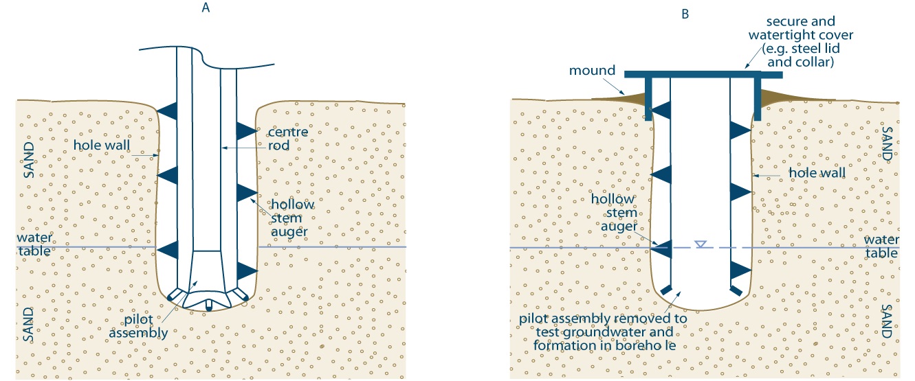
Figure 6-27 shows a cross-sectional diagram of two uncased wells (A and B) placed into a sand deposit constructed by augering.
The well on the left of the diagram is example “A”. A hollow stem auger flight extends into a hole. A centre rod is located with the auger flight. At the bottom of the auger flights, a pilot assembly is attached to the bottom of the centre rod. A horizontal water line in the subsurface extends through the well. The horizontal water line represents the water table.
The well on the right of the diagram is example “B”. A hollow stem auger flight extends into a hole. The centre rod and pilot assembly have been removed from the auger. A horizontal water line in the subsurface extends through the well. The horizontal water line represents the water table. A secure and watertight steel cover (e.g., steel lid and collar) have been placed over the hole and auger flight. The ground surface has been mounded away from the cover.
Note 1 states the hole is constructed and held open by using hollow-stem auger flights
Note 2 states the well cover must be placed securely on the well and placed in a manner sufficient to prevent the entry of surface water and other foreign materials whenever the test hole or dewatering well is left unattended. The well cover could consists of a watertight steel collar and lid as shown in B.
Reminder - For more information about temporary covers see “Best Management Practice – Covering Test Holes or Dewatering Wells without Casing” on page 96 of this chapter.
Reminder - This figure is not to scale, is for illustrative purposes for this chapter only, and does not necessarily represent full compliance with the requirements found in the Wells Regulation.
Figure 6-28: Examples of Uncased Well Constructed by Diamond Drilling (Scheduled to be Abandoned not Later than 30 Days After Completion of Structural Stage)
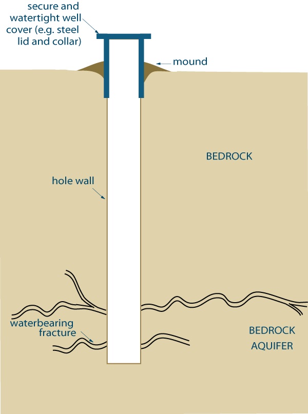
Figure 6-28 shows a cross-sectional diagram of an uncased well constructed by diamond drilling.
The well extends vertically into a bedrock formation and has encountered water bearing fractures or a bedrock aquifer. A secure and watertight steel cover (e.g., steel lid and collar) have been placed over the hole. The ground surface has been mounded away from the cover.
Note 1 states the hole is constructed by diamond drilling equipment and the bedrock is strong enough to hold the hole open. As this well is uncased, an annular space does not exist.
Note 2 states the well cover must be placed securely on the well and placed in a manner sufficient to prevent the entry of surface water and other foreign materials whenever the test hole or dewatering well is left unattended. The well cover could consists of a watertight steel collar and lid as shown.
Reminder - For more information about temporary covers see “Best Management Practice – Covering Test Holes or Dewatering Wells without Casing” on page 96 of this chapter.
Reminder - This figure is not to scale, is for illustrative purposes for this chapter only, and does not necessarily represent full compliance with the requirements found in the Wells Regulation.
Figure 6-29: Examples of Well Construction with Use of Hollow-Stem Auger in Conjunction with Drilling (Schedule to be Abandoned not Later Than 30 Days After Completion of Structural Stage)
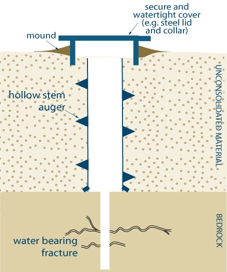
Figure 6-29 shows a cross-sectional diagram of an uncased well constructed by hollow-stem augering and diamond drilling.
The well extends vertically through an unconsolidated material (overburden) and into a bedrock formation. A hollow stem auger flight extends into a hole. The centre rod and pilot assembly have been removed from the auger. In the bedrock formation, the well has encountered water bearing fractures or a bedrock aquifer. A secure and watertight steel cover (e.g., steel lid and collar) have been placed over the hole. The ground surface has been mounded away from the cover.
Note 1 states the figure shows an example where it may be possible to auger through the overburden, but not the entire desired depth of the well. In this example, a hollow-stem auger has created a hole through the overburden. A drilling system has been used to complete the remainder of the test hole in the bedrock.
Note 2 states the well cover must be placed securely on the well and placed in a manner sufficient to prevent the entry of surface water and other foreign materials whenever the test hole or dewatering well is left unattended. The well cover could consists of a watertight steel collar and lid as shown.
Reminder - For more information about temporary covers see “Best Management Practice – Covering Test Holes or Dewatering Wells without Casing” on page 96 of this chapter.
Reminder - This figure is not to scale, is for illustrative purposes for this chapter only, and does not necessarily represent full compliance with the requirements found in the Wells Regulation.
Figure 6-30: Example of Dug Test Hole (Not Scheduled to be Abandoned Within 180 Days After Completing Structural Stage)
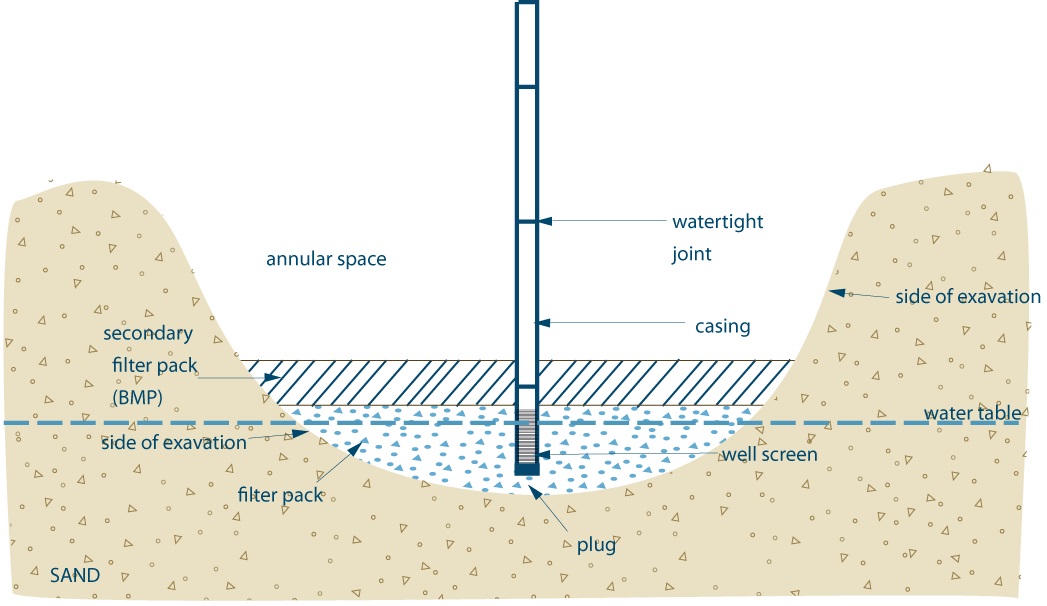
Figure 6-30 shows a cross-sectional diagram of a dug well placed a sand deposit.
The dug well consists of a large open hole. A layer of filter pack has been placed at the bottom of the hole. A casing extends vertically from above the ground surface to the filter pack. The joints between the sections of casing have been made watertight. A well screen is attached to the bottom of the casing. A plug is attached to the bottom of the well screen. A filter pack has been placed around the well screen to the side of the hole. As a best management practice, a secondary filter pack has been placed on top of the filer pack. The top of the secondary filter pack extends above the top of the well screen. An annular space exists above the secondary filter pack.
Note 1 states best management practice.
Note 2 states the filling material around and above the well screen must be clean washed gravel or sand. Native materials can also be used in the annular space instead of sand or gravel if the well is not constructed in a contaminated area and the materials are excavated separately, stored separately and kept free from contamination and backfilled in the same relative position they originally occupied.
Reminder - See “Best Management Practice – Use of Primary and Secondary Filter Packs,” on page 95 of this chapter for more information.
Reminder - This figure is not to scale, is for illustrative purposes for this chapter only, and does not necessarily represent full compliance with the requirements found in the Wells Regulation.
\
Figure 6-31: Example of Dewatering Wells Constructed With the Use of Driven Points
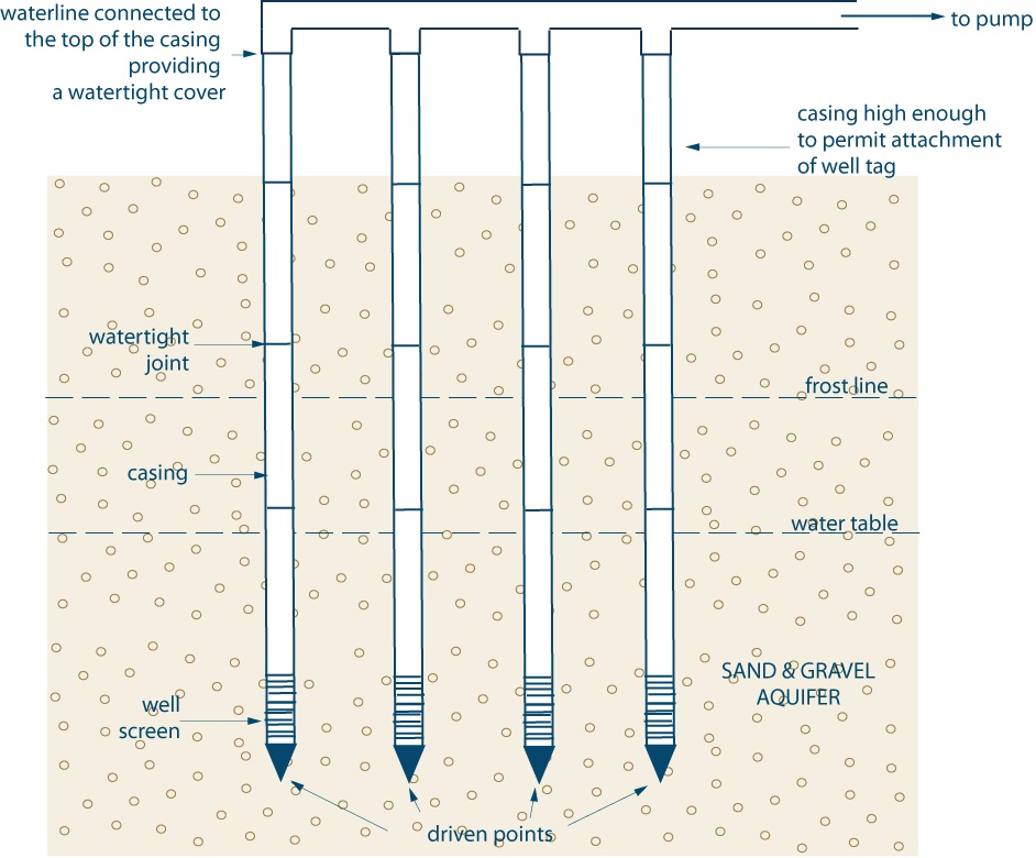
Figure 6-31 shows a cross-sectional diagram of dewatering wells constructed by driving.
The diagram shows 4 driven point wells. The casing for each of the wells extends from above the ground surface into a sand and gravel deposit. The casing of each of the wells is high enough to permit the attachment of a well tag. The joints between the sections of casing have been made watertight. A well screen is attached to the bottom of each of the casings. A driven point has been attached to the bottom of each well screen. The well screens are located in a sand and gravel aquifer in the overburden. A horizontal dotted line above the well screen represents the water table.
The top of the casing for each of the wells are attached to a horizontal waterline. Water flows from the well through the casing and waterline to a pump (not shown). The waterline connected to the top of the casing provides a watertight cover.
Note 1 states in this example, the dewatering wells are driven into the ground and do not create an annular space. The dewatering wells are used to lower the water table in a given area to allow for construction projects such as sewer and water main installations.
Reminder - This figure is not to scale, is for illustrative purposes for this chapter only, and does not necessarily represent full compliance with the requirements found in the Wells Regulation.
Figure 6-32: Example of Dewatering Well Constructed by Jetting with the use of a Driven Point (Not Scheduled to be Abandoned Within 180 Days After Completing Structural Stage)
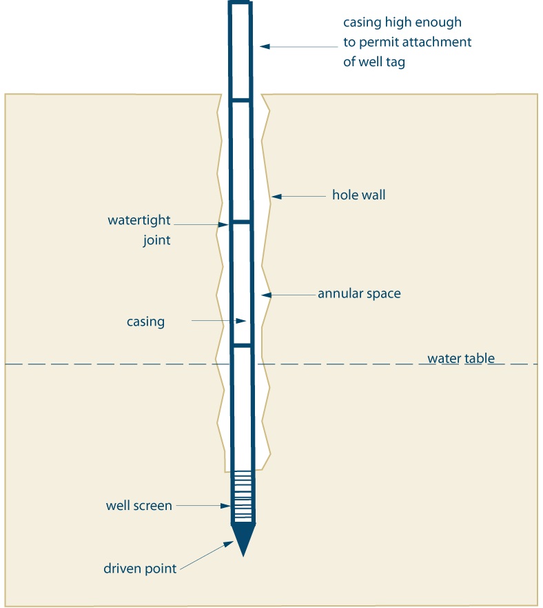
Figure 6-32 shows a cross-sectional diagram of a dewatering well constructed by jetting.
The diagram shows the casing extending from above the ground surface into the subsurface. The casing is high enough to permit the attachment of a well tag. The joints between the sections of casing have been made watertight. A well screen is attached to the bottom of the casing. A driven point has been attached to the bottom of the well screen. A horizontal dotted line above the well screen represents the water table. An irregular annular space has been created above the well screen.
Note 1 states in this example, the dewatering well is jetted into the ground, creating an irregular annular space.
Reminder - This figure is not to scale, is for illustrative purposes for this chapter only, and does not necessarily represent full compliance with the requirements found in the Wells Regulation.
Figure 6-33: Example of Dewatering Well Construction by Direct Push equipment Using a Driven Point (No Scheduled to be Abandoned Within 180 Days After Completing Structural Stage)
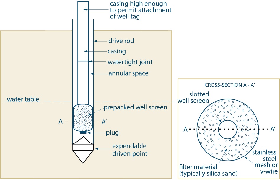
Figure 6-33 shows a cross-sectional diagram of a dewatering well constructed by direct push using a driven point.
The diagram shows a well with drive rod extending from the ground surface into the subsurface. An expendable driven point is located at the bottom of the drive rod.
Within the drive rod, a casing extends from above the ground surface into the subsurface. The casing is high enough to permit the attachment of a well tag. The joints between the sections of casing have been made watertight. A prepacked well screen is attached to the bottom of the casing. A plug is located at the bottom of the well screen. A horizontal dotted line above the well screen represents the water table.
Another horizontal dotted line with the text: A – A’, is shown extending through the prepacked well screen.
To the right of the cross sectional diagram there is another diagram that states “Cross-section A – A’”. This diagram shows a circle that represents a stainless steel mesh or “v-wire”. Within the mesh/v-wire is slotted well screen tube. Filter material (typically silica sand) is located between the well screen tube and the mesh/v-wire. A horizontal dotted line with the text: A – A’, is shown extending through the mesh/v-wire, filter material and well screen tube.
Note 1 states in this example, drive rods with a detachable (expendable) drive point are driven into the ground. A prepacked well screen with casing is installed.
- In this example, drive rods with a detachable (expendable) drive point are driven into the ground. A prepacked well screen with casing is installed into the drive rods. As annular space is present between the drive rods and the casing. The drive rods will be removed once the sealant is placed into the annular space.
- Since a driven point is used in the constuction, material and a method approved by the Director must be used to fill the annular space (See Chapter 7L Annular Space & Sealing for further infomation).
Reminder - This figure is not to scale, is for illustrative purposes for this chapter only, and does not necessarily represent full compliance with the requirements found in the Wells Regulation.
Footnotes
- footnote[1] Back to paragraph ASTM International, West Conshohocken, PA
- footnote[2] Back to paragraph ASTM International, West Conshohocken, PA
- footnote[3] Back to paragraph Modified from: US Army Corp of Engineers. 1998. Monitoring Well Design at Hazardous, Toxic, and Radioactive Waste Sites (EM 1110-1-4000) Table 3-1,page 3-3.
- footnote[4] Back to paragraph Modified from: Fleming College. 2008. Manual for Continuing Education Course Monitoring Wells – Construction (for Ontario Well Technicians): Table 6, p. 64.
- footnote[5] Back to paragraph Modified from: Sterrett, Robert J. 2007. Groundwater and Wells: Third Edition. Johnson Screen/a Weatherford Company, New Brighton, Minnesota. Table 7.3, P283.
- footnote[6] Back to paragraph Powers, J. Patrick, Arthur B. Corwin, Paul C. Schmall and Walter E. Kaeck. 2007. Construction Dewatering and Groundwater Control – New Methods and Applications: Third Edition. John Wiley and Sons Inc., Hoboken, New Jersey
- footnote[7] Back to paragraph Modified from: Powers, J. Patrick, Arthur B. Corwin, Paul C. Schmall and Walter E. Kaeck. 2007. Construction Dewatering and Groundwater Control – New Methods and Applications: Third Edition. John Wiley and Sons Inc., Hoboken, New Jersey. Table 16.3, P250.
- footnote[8] Back to paragraph Nielsen, David M. 2006. Practical Handbook of Environmental Site Characterization and Ground-water Monitoring: Second Edition. CRC – Taylor & Francis Group. Boca Raton, FL.
- footnote[9] Back to paragraph Powers, J. Patrick, Arthur B. Corwin, Paul C. Schmall and Walter E. Kaeck. 2007. Construction Dewatering and Groundwater Control – New Methods and Applications: Third Edition. John Wiley and Sons Inc., Hoboken, NJ.
- footnote[10] Back to paragraph Sterrett, Robert J. 2007. Groundwater and Wells, Third Edition. Johnson Screens/ a Weatherford Company, New Brighton, MN.
- footnote[12] Back to paragraph Fleming College. 2008. Course Manual for Well Constructed: Training for Assistant Well Technicians in Ontario. Chapter 7, Figure 7-7.
- footnote[13] Back to paragraph footnote here
- footnote[14] Back to paragraph Fleming College. 2008. Course Manual for Well Constructed: Training for Assistant Well Technicians in Ontario. Chapter 3, Table 3-9.
- footnote[15] Back to paragraph Tucker, Maurice, E. 2003. Sedimentary Rocks in the Field. John Wiley and Sons Ltd. ISBN: 0-470-85123-6. Table 4.2., P69
- footnote[16] Back to paragraph DeJong, J.T. and Boulanger, R.W. (2000) "Introduction to Drilling and Sampling in Geotechnical Practice", Educational Video, 2nd Edition, Department of Civil and Environmental Engineering, University of California, Davis, 35 min.
- footnote[17] Back to paragraph Photo courtesy of Eijkelkamp
- footnote[18] Back to paragraph Australian Drilling Industry Training Committee Limited. 1996. Drilling: The Manual of Methods, Applications, and Management. CRC – Lewis. Boca Raton.
- footnote[19] Back to paragraph DeJong, J.T. and Boulanger, R.W. (2000) "Introduction to Drilling and Sampling in Geotechnical Practice", Educational Video, 2nd Edition, Department of Civil and Environmental Engineering, University of California, Davis, 35 min.
- footnote[20] Back to paragraph Photo courtesy of Charles A Templeton Machine Inc.
- footnote[21] Back to paragraph U.S. Bureau of Reclamation. 1998. Earth Book Manual, Part I, 3rd Edition. Denver, Colorado Figure 2-35, P139
- footnote[22] Back to paragraph ASTM International, West Conshohocken, PA, ASTM website.
- footnote[23] Back to paragraph Nielsen, David M. 2006. Practical Handbook of Environmental Site Characterization and Ground-Water Monitoring, Second Edition. CRC Press.
- footnote[24] Back to paragraph Ontario Ministry of Environment and Energy Standards Development Branch. 1996. Guidance on Sampling and Analytical Methods for Use at Contaminated Sites in Ontario: Version 1.1. ISBN-0-7778-4056-1
- footnote[25] Back to paragraph National Institute for Occupational Safety and Health (NIOSH). 1985. Occupational Safety and Health Guidance Manual for Hazardous Waste Site Activities. DHHS(NIOSH) Publication No. 85-115, US Government Printing Office, Washington DC.
- footnote[26] Back to paragraph Nielsen, David M. 2006. Practical Handbook of Environmental Site Characterization and Ground-water Monitoring: Second Edition. CRC/Taylor & Francis Group. Boca Raton, FL.
- footnote[27] Back to paragraph HAZWOPER. 1989. Hazardous Waste Operations and Emergency Response, Final Rule. 29 CFR 1910.120, 54 FR 9294, March 6, 1989.
- footnote[28] Back to paragraph ASTM International, West Conshohocken, PA, ASTM website.
- footnote[29] Back to paragraph (DOI: 10.1520/D5088-02R08). ASTM International, West Conshohocken, PA, ASTM website
- footnote[30] Back to paragraph Nielsen, David M. 2006. Practical Handbook of Environmental Site Characterization and Ground-water Monitoring: Second Edition. CRC/Taylor & Francis Group. Boca Raton, FL.
- footnote[31] Back to paragraph (DOI: 10.1520/D5092-04E01). ASTM International, West Conshohocken, PA, ASTM website
- footnote[32] Back to paragraph World Health Organization. 2006. Guidelines for Drinking-water Quality, First Addendum to the Third Edition, Volume 1, Recommendations – 3rd Edition. ISBN 92 4 154696 4 (NLM Classification: WA 675) Electronic version available online: http://www.who.int/water_sanitation_health/dwq/gdwq3rev/en/
- footnote[33] Back to paragraph (DOI: 10.1520/C0478-13). ASTM International, West Conshohocken, PA, ASTM Website
- footnote[34] Back to paragraph (DOI: 10.1520/F0480-06BE01). ASTM International, West Conshohocken, PA, ASTM website.
- footnote[35] Back to paragraph (DOI: 10.1520/C0990-09). ASTM International, West Conshohocken, PA, ASTM website
- footnote[36] Back to paragraph (DOI:10.1520/D5088-02R08). ASTM International, West Conshohocken, PA, .
- footnote[37] Back to paragraph (DOI: 10.1520/D5092-04E01). ASTM International, West Conshohocken, PA, ASTM webite
- footnote[38] Back to paragraph Powers, J. Patrick, Arthur B. Corwin, Paul C. Schmall and Walter E. Kaeck. 2007. Construction Dewatering and Groundwater Control – New Methods and Applications: Third Edition. John Wiley and Sons Inc., Hoboken, New Jersey.
- footnote[39] Back to paragraph Powers, J. Patrick, Arthur B. Corwin, Paul C. Schmall and Walter E. Kaeck. 2007. Construction Dewatering and Groundwater Control – New Methods and Applications: Third Edition. John Wiley and Sons Inc., Hoboken, New Jersey.
- footnote[40] Back to paragraph Sterret, Robert J. 2007. Groundwater & Wells: Third Edition. Johnson Screens/a Weatherford Company. New Brighton, MN.
- footnote[41] Back to paragraph Powers, J. Patrick, Arthur B. Corwin, Paul C. Schmall and Walter E. Kaeck. 2007. Construction Dewatering and Groundwater Control – New Methods and Applications: Third Edition. John Wiley and Sons Inc., Hoboken, New Jersey.
- footnote[42] Back to paragraph Powers, J. Patrick, Arthur B. Corwin, Paul C. Schmall and Walter E. Kaeck. 2007. Construction Dewatering and Groundwater Control – New Methods and Applications: Third Edition. John Wiley and Sons Inc., Hoboken, New Jersey.
- footnote[43] Back to paragraph McCarthy, David F. 1998. Essentials of Soil Mechanics and Foundations – Basic Geotechnics: Fifth Edition. Prentice Hall. Upper Saddle River, New Jersey. Page 96.
- footnote[44] Back to paragraph (DOI: 10.1520/D5092-04E01). ASTM International, West Conshohocken, PA, ASTM website
- footnote[45] Back to paragraph Powers, J. Patrick, Arthur B. Corwin, Paul C. Schmall and Walter E. Kaeck. 2007. Construction Dewatering and Groundwater Control – New Methods and Applications: Third Edition. John Wiley and Sons Inc., Hoboken, New Jersey
- footnote[46] Back to paragraph Sterret, Robert J. 2007. Groundwater & Wells: Third Edition. Johnson Screens/a Weatherford Company. New Brighton, MN.
- footnote[47] Back to paragraph (DOI: 10.1520/C0478-13). ASTM International, West Conshohocken, PA, ASTM website
- footnote[48] Back to paragraph Sterret, Robert J. 2007. Groundwater & Wells: Third Edition. Johnson Screens/a Weatherford Company. New Brighton, MN. P491
- footnote[49] Back to paragraph Sterret, Robert J. 2007. Groundwater & Wells: Third Edition. Johnson Screens/a Weatherford Company. New Brighton, MN. P491
- footnote[50] Back to paragraph Sterret, Robert J. 2007. Groundwater & Wells: Third Edition. Johnson Screens/a Weatherford Company. New Brighton, MN. P491
- footnote[51] Back to paragraph Sterret, Robert J. 2007. Groundwater & Wells: Third Edition. Johnson Screens/a Weatherford Company. New Brighton, MN. P470
- footnote[52] Back to paragraph Sterret, Robert J. 2007. Groundwater & Wells: Third Edition. Johnson Screens/a Weatherford Company. New Brighton, MN. P478
- footnote[53] Back to paragraph Figure based on: ASTM D5784 - 95(2006) – “Standard Guide for Use of Hollow-Stem Augers for Geoenvironmental Exploration and the Installation of Subsurface Water-Quality Monitoring Devices.” (DOI: 10.1520/D5784-95R06). ASTM International, West Conshohocken, PA, ASTM website.